EP0122302A1 - Dispositif pour la lecture et/ou pour l'enregistrement des informations d'un support d'informations en forme d'une carte - Google Patents
Dispositif pour la lecture et/ou pour l'enregistrement des informations d'un support d'informations en forme d'une carte Download PDFInfo
- Publication number
- EP0122302A1 EP0122302A1 EP83103542A EP83103542A EP0122302A1 EP 0122302 A1 EP0122302 A1 EP 0122302A1 EP 83103542 A EP83103542 A EP 83103542A EP 83103542 A EP83103542 A EP 83103542A EP 0122302 A1 EP0122302 A1 EP 0122302A1
- Authority
- EP
- European Patent Office
- Prior art keywords
- card
- lock
- information
- slot
- movement
- Prior art date
- Legal status (The legal status is an assumption and is not a legal conclusion. Google has not performed a legal analysis and makes no representation as to the accuracy of the status listed.)
- Withdrawn
Links
Images




Classifications
-
- G—PHYSICS
- G06—COMPUTING OR CALCULATING; COUNTING
- G06K—GRAPHICAL DATA READING; PRESENTATION OF DATA; RECORD CARRIERS; HANDLING RECORD CARRIERS
- G06K13/00—Conveying record carriers from one station to another, e.g. from stack to punching mechanism
- G06K13/02—Conveying record carriers from one station to another, e.g. from stack to punching mechanism the record carrier having longitudinal dimension comparable with transverse dimension, e.g. punched card
- G06K13/08—Feeding or discharging cards
- G06K13/0868—Feeding or discharging cards using an arrangement for keeping the feeding or insertion slot of the card station clean of dirt, or to avoid feeding of foreign or unwanted objects into the slot
- G06K13/0875—Feeding or discharging cards using an arrangement for keeping the feeding or insertion slot of the card station clean of dirt, or to avoid feeding of foreign or unwanted objects into the slot the arrangement comprising a shutter for blocking at least part of the card insertion slot
-
- G—PHYSICS
- G06—COMPUTING OR CALCULATING; COUNTING
- G06K—GRAPHICAL DATA READING; PRESENTATION OF DATA; RECORD CARRIERS; HANDLING RECORD CARRIERS
- G06K13/00—Conveying record carriers from one station to another, e.g. from stack to punching mechanism
- G06K13/02—Conveying record carriers from one station to another, e.g. from stack to punching mechanism the record carrier having longitudinal dimension comparable with transverse dimension, e.g. punched card
- G06K13/08—Feeding or discharging cards
-
- G—PHYSICS
- G06—COMPUTING OR CALCULATING; COUNTING
- G06K—GRAPHICAL DATA READING; PRESENTATION OF DATA; RECORD CARRIERS; HANDLING RECORD CARRIERS
- G06K7/00—Methods or arrangements for sensing record carriers, e.g. for reading patterns
- G06K7/08—Methods or arrangements for sensing record carriers, e.g. for reading patterns by means detecting the change of an electrostatic or magnetic field, e.g. by detecting change of capacitance between electrodes
- G06K7/082—Methods or arrangements for sensing record carriers, e.g. for reading patterns by means detecting the change of an electrostatic or magnetic field, e.g. by detecting change of capacitance between electrodes using inductive or magnetic sensors
- G06K7/083—Methods or arrangements for sensing record carriers, e.g. for reading patterns by means detecting the change of an electrostatic or magnetic field, e.g. by detecting change of capacitance between electrodes using inductive or magnetic sensors inductive
- G06K7/084—Methods or arrangements for sensing record carriers, e.g. for reading patterns by means detecting the change of an electrostatic or magnetic field, e.g. by detecting change of capacitance between electrodes using inductive or magnetic sensors inductive sensing magnetic material by relative movement detecting flux changes without altering its magnetised state
-
- G—PHYSICS
- G06—COMPUTING OR CALCULATING; COUNTING
- G06K—GRAPHICAL DATA READING; PRESENTATION OF DATA; RECORD CARRIERS; HANDLING RECORD CARRIERS
- G06K7/00—Methods or arrangements for sensing record carriers, e.g. for reading patterns
- G06K7/08—Methods or arrangements for sensing record carriers, e.g. for reading patterns by means detecting the change of an electrostatic or magnetic field, e.g. by detecting change of capacitance between electrodes
- G06K7/082—Methods or arrangements for sensing record carriers, e.g. for reading patterns by means detecting the change of an electrostatic or magnetic field, e.g. by detecting change of capacitance between electrodes using inductive or magnetic sensors
- G06K7/087—Methods or arrangements for sensing record carriers, e.g. for reading patterns by means detecting the change of an electrostatic or magnetic field, e.g. by detecting change of capacitance between electrodes using inductive or magnetic sensors flux-sensitive, e.g. magnetic, detectors
Definitions
- the invention relates to a device for reading out and / or storing information from a card-shaped data carrier.
- cards carrying information serve, for example, as credit cards or cards for identifying a person when entering a company.
- Known devices of the type mentioned at the outset are used to identify credit cards, check cards, entry badges or the like.
- Card readers in which the information is exchanged when the card is fixed in the card reader have hitherto had a fixed reading device which responds, for example, to holes, to capacitive or inductive elements arranged in the card.
- the information is contained in a magnetic track attached to the card and the card is pulled by a drive device at a constant speed past a fixed magnetic head, which reads out and / or stores the information stored in the magnetic track, for example in automated teller machines.
- Devices of this type can be designed such that either only information contained on the card is read out, but it is also possible to additionally write information into the card, for example an account balance.
- a data processing system connected to the device can read the current account balance from the card and write a change in the account balance back into the card.
- Such a method can be used, for example, for tickets in which corresponding signals are generated at the start and end of the journey and the determined route is "debited" from the card in the form of fee units until the total fare paid when the card was purchased is used up.
- the card reader takes cards inserted into it by hand and transfers them to a position that is no longer accessible from the outside for information exchange, that is to say passes under the information head and, after reading in and / or reading out, transports them back into a position , in which the card is again gripped by hand from the outside and can be removed. If such a card transport is missing, the card may only be inserted into the card reader to such an extent that a section of the card is still gripped from the outside and can be removed from the device by hand after the information exchange.
- the invention is therefore based on the object of developing a card reader with a fixed card during the information exchange, in which to increase operational security and to protect against misuse, the information exchange only takes place when the card is in the correct position, and in which the information exchange cannot be disturbed, although part of the card still protrudes from the device and can be gripped by hand.
- the card reader is provided on at least one side edge of a slot for inserting the cards, at least one sensor which only enables the exchange of information to be started when it is in a position deflected by the card .
- the card is always inserted in the correct position in the card reader if the slot of the card reader is only wider by the necessary play than the length of the smaller side of the rectangle. Due to the size of the slot, the card must always be inserted lengthways into the card reader. However, this has the disadvantage that the area available for storing the information on the map is essentially determined by the size of the narrow side of the rectangle. If, however, the width of the insertion slot corresponds to the size of the larger side of the rectangle, there is the possibility of inserting the card into the width of this slot, so that the area available for storing the information is determined by the size of the longer side of the rectangle. However, a slot that is matched to the longer rectangular side of the card has the disadvantage that the card can not only be inserted into the slot, as desired, in width, but also in length, which opens up opportunities for misuse.
- the design according to the invention has the advantage that the information exchange is only started when the width of the card is inserted.
- the design according to the invention can, however, be used not only when the cards are inserted into the card reader in width, but also when cards are inserted into the card reader according to their length. In this case it is ensured by the invention that only those cards can bring about an exchange of information in which the length or width of the card matches the slot width so precisely that the sensors in this slot are deflected to such an extent that the information exchange is started becomes.
- opposite sensors can be provided on both lateral edges of the insertion slot, and the switching means actuated by these sensors can be connected in series so that there is only the possibility of information exchange if both sensors are deflected in their by an assigned card Position. It is then not possible for the information exchange to be switched on by an obliquely inserted card.
- the object of the invention is also achieved in that the card reader has at least one lock for holding the card during the exchange of information. This prevents the card from being moved during the information exchange, even though part of the card is still outside the card reader.
- sensors arranged on the lateral edges of the insertion slot can be combined with the last-mentioned lock for holding the card, so that the interaction of these two features meets the increased security requirements for certain uses of the card reader.
- the invention can be used to advantage both in embodiments in which the reading device is arranged fixed to the device in the card reader and in card readers in which an information head is moved over the information magnetically or otherwise stored on the card by a device-specific drive.
- At least one stop limiting the insertion of the card is movably arranged, which only releases the information exchange in a position deflected by the card.
- the lock according to the invention can be designed in various ways in embodiments of the invention.
- the lock is designed as a stop engaging in a cutout in the card.
- the lock is designed as a locking member which engages on the rear edge of the card, for example as a movable hook which overlaps the rear edge of the card in the locked position.
- These embodiments have the advantage that the card does not have to have a recess and therefore commercially available blanks can be used.
- a recess in the card, in which a locking member engages when the card is inserted has the advantage that this recess serves as an additional identification feature; Cards that do not have the recess are not accepted by the card reader.
- a housing part delimiting the outer end of the insertion slot has a section which projects beyond the rear end of the card when the card is fully inserted into the slot, and a second section which extends beyond the rear end of the fully inserted card.
- a locking member for example an axially displaceable pin
- the other housing section steps back towards the rear edge of the card, so that the completely inserted card is still in the area of this section easily grasped by hand and after exchanging information and unlocking the card can be removed again from the card reader.
- the lock can also or additionally have levers pressing the card against a base, which can preferably be movably guided in the manner of clamping ratchets.
- the drives of the two locking devices can be coupled to one another. This also results in a secure locking of the card during the exchange of information.
- this embodiment of the invention has the advantage that it straightens cards which are somewhat curved due to being carried in the pocket by being pressed against a flat base, so that an information head guided over the card finds a flat information track.
- a device for starting the information exchange can be prepared by a part moved when the card is inserted and can be triggered by an end stop.
- This embodiment also serves as an additional safeguard against misuse and damage.
- the parts carrying out the information exchange are usually sensitive; if these parts are not fixed but are arranged in the housing so that they can be moved over the card, they should not be able to be moved into the area of the slot when an object other than the card is pressed against the end stop . Therefore, in one embodiment of the invention, the part moved when inserting the card is replaced by one or two of the parts already in the previously described sensors formed, which protrude laterally into the insertion slot and scan the lateral dimension of the card.
- the preparation by a moving part when inserting the card and the triggering by an end stop can be done in the usual way via microswitches, which are connected in series, for example, and are switched on, for example, in the circuit of a drive motor, which uses a threaded spindle to drive a drive head over the Card contained information is moved away.
- microswitches which are connected in series, for example, and are switched on, for example, in the circuit of a drive motor, which uses a threaded spindle to drive a drive head over the Card contained information is moved away.
- this preparation and triggering of the information exchange is realized mechanically in other embodiments of the invention.
- a housing of a switch for starting the information exchange is movably guided in two positions and its movement in at least one of the two positions is derived from the movement of a part moved by the insertion of the card, for example from the movement of one or more the width of the card scanning sensor, and the movement of a part acting on the actuator of the switch is guided by the movement of the stop limiting the insertion of the card.
- the switches can be mechanically connected to the sensors and can therefore be movable in the axial direction of the sensors.
- the movement of the parts forming the lock into the locked position can be derived from the drive of an information head. In other embodiments of the invention, however, the movement of the parts forming the lock into the locked position takes place by spring action. This has the advantage that the cards can only be securely actuated by pressing locking elements because, in contrast to the bars in the card which have cut-outs, they cannot have the exact same locking position for each card due to the tolerances of the card thickness or with slightly bent cards take in.
- This embodiment of the invention can be further developed in such a way that the movement of a locking member holding the locking members against the spring action in the unlocked position into its unlocking position is derived from the movement of an information head within a first movement section, the information head only after passing through the first movement section and thus only after unlocking the locking elements locking the card, does the track contained on the card reach, in which the information is stored.
- This embodiment of the invention may be designed to the effect further, that in the housing displaceable a spool - is guided bar, the movement of the locking members is derived from the movement of that one engages the slide him corresponding working position pulling spring in one of the locked position of the locking members and that a lever transmission is provided, by means of which the slide can be moved into its rest position by the information head moving back against the action of the spring.
- the locking levers acting as a clamping lock are designed as two-armed angle levers, one end of which is pivotably mounted in the slide and the other end of which is intended for engagement in the insertion slot, but the angle apex of which is pivotally mounted in the housing.
- the distance of the bearing axis in the housing from the bearing axis in the slide is greater than the distance of the bearing axis in the housing from the lever end engaging in the insertion slot.
- the angle of one lever arm, which connects the two bearing axles to one another, to the other lever arm of the angle lever, which connects the bearing axis located at the angle vertex to the free lever end engaging in the insertion slot, is selected, for example between 150 and 170 °, with comparatively low, the pivoting movement of the lever-causing forces, a very high contact pressure which engages in the insertion slot and presses the card onto the base of the lever ends is generated.
- the movement of a locking pin which engages in the insertion slot of the device is also derived from the movement of the slide.
- the slider can have an oblique guide, into which the inner end of a two-armed lever engages, which is pivotally mounted in the housing and whose outer end engages in a recess of a locking pin which is movable in the housing transversely to the insertion slot behind the rear end of the complete inserted card can be inserted into the slot.
- the end stop consists of a rail with a U-profile which is open towards the insertion side, the rail being mounted so that it can move in the insertion direction.
- Another possibility for manipulating the device is that flat objects can be inserted into the device through the slot for inserting the card, it is also possible to damage the inside of the device, in particular the very sensitive read / write unit.
- the invention is also based on the object to develop a card reader with a fixed during the exchange of information, in which to increase operational security and protection against misuse, the insertion of the card is only possible and the information is only exchanged when the card is in in the correct position, and in which the information exchange cannot be disrupted, even though part of the card still protrudes from the device and can be gripped by hand.
- This device thus has the considerable advantage that an exchange of information is prevented simply because an object other than a card with predetermined dimensions cannot be inserted into the device at all. Misuse of the device or damage is thus largely excluded.
- the latter object is further achieved according to the invention in that the second lock blocks the insertion path behind the card at least two points when the card is fully inserted.
- This subordinate solution to the object of the invention has the essential advantage that it is impossible to pull out the card during the exchange of information because the path of the card is completely blocked.
- the arrangement according to the invention has the advantage that the card itself cannot be pulled out "by force”. This also applies to arrangements in which the back of the card is locked only by a single locking pin on the side edge of the card, so that the card can be tilted under certain circumstances if the card edge is firmly engaged. This enables a completely secure operation that is practically completely secured against manipulation and malfunctions during data exchange.
- a particularly perfect backup of the device and the workflow during data exchange is obtained if, in a preferred embodiment of the invention, the two secondary solutions are used together or in combination with the features mentioned at the beginning.
- an embodiment is preferred in which the locks are actuated by a common actuating member. This results in a minimization of the required components, a particularly compact structure and high operational reliability.
- the actuator is particularly advantageous to design the actuator as a motor-driven shaft with eccentrics.
- flexible operation is possible by controlling the motor accordingly, and secondly, the actuation of the locks by means of eccentrics is particularly reliable and can also exert sufficient mechanical forces.
- the first lock in order to actuate the first lock, which in the first place releases the slot into the interior of the device, it can be actuated by first eccentrics, which are put into operation when the card actuates the sensors arranged on the side. If a sensor is provided on each side of the slot at a distance at which both sensors are only actuated when a card of a predetermined width is inserted into the slot, it is possible to reliably recognize a predetermined card width.
- the sensors actuate switches which are logically connected, preferably in series connection, in such a way that the motor is actuated only when both switches are activated at the same time. With very simple coding, it is therefore possible to reliably recognize predetermined card formats.
- the first lock is designed as a sheet metal part closing the slot in the rest position, a particularly simple and reliable construction is possible. With a compact construction of the interior of the device, the sheet metal part can be guided so tightly that a violent insertion of an object against the sheet metal part closing the slot is practically impossible.
- the sheet metal part is resiliently suspended according to the invention, in particular in that a spring wire is fastened in a tab formed on the sheet metal part and is held at its ends, preferably by recesses formed on bearing blocks of the shaft, a control can be provided in which the eccentric detaches the tabs of the sheet metal part actuated in the rest position and pushing the sheet metal part in front of the slot, while the eccentric lifts off the tab when the card is inserted and the sheet metal part is then held in a spring-loaded manner by the spring wire.
- This mode of operation guarantees that a particularly stable closure is achieved when the slot is closed by the engagement of the eccentric on the tab, while the sheet-metal part serving as a lock can only be suspended in a loosely resilient manner when the card is inserted.
- the second lock which holds the card in the fully inserted state, is preferably actuated by second eccentrics, which are also driven by the motor.
- the second lock is only activated when the card operates the switch when it is fully inserted.
- This electromechanical locking system can also - as already explained above - be set up particularly simply and effectively.
- a particularly good effect is achieved in that the card actuates two switches with their edge areas of the front edge pointing into the device in the inserted state, which are logically connected, preferably in series connection, that the motor is actuated only when both switches respond simultaneously.
- the actuation of the first lock only cards with predetermined dimensions can actuate the device in this way.
- the switches acting in the insertion direction of the card for the second lock respond to a uniform height of the card, so that in the possible combination of the two subordinate solutions according to the invention mentioned above, one Monitoring of both map dimensions is possible.
- a time control can be provided according to the invention which, after the second lock takes effect, switches on a read / write unit for data exchange from or to the card and releases the second lock again after the data exchange has ended.
- This time control therefore ensures that the card is immovably fixed during the data exchange and can be removed by hand immediately after the end of the data exchange.
- the second lock is formed by hooks which, in the working position, comprise the edge of the card which points away from the device when the card is inserted. These hooks can therefore be used to reliably prevent the card from being manually removed from the device during data exchange.
- the device comprises a front part which has an indentation extending in the horizontal direction, such that when the card is inserted, the central region of the rear edge thereof can still be grasped by hand, while the lateral edges of the rear edge are already in the front part.
- the hooks are arranged in the front part.
- the hooks of the second lock can take effect in this area without being visible or accessible from the outside.
- the hooks forming the second lock are largely protected from external interference and therefore damage, since they only engage in the working position in the slot forming the insertion path for the card and are therefore practically inaccessible from the outside.
- the hooks form an arm of a lever pivotable about an axis, the other arm of which ends in a fork which surrounds the second eccentric arranged on the shaft.
- the locking of the card by the second lock is therefore formed by swivel levers, one arm of which forms the hooks mentioned.
- the deflection of the swivel lever can be done in the form mentioned simply by turning the shaft with the eccentrics located on it.
- This arrangement is also mechanically particularly simple and allows sufficient mechanical forces to be effective within the second lock.
- the second lock is preferably put into operation by the card actuating the switches via sliders.
- This interposition of sliders between card and switch has the advantage that the switch can be positioned at practically any point on the inside of the device and that on the other hand additional structural measures are possible, for example a spring actuation of the switch, an exact definition of a stop for the card and a strictly linear guidance of the card the aforementioned recognition of whether the depth of the map has a certain dimension.
- a table or a floor is arranged inside the device, which has a guide for the slide. In this way, tilting of the actuating device for the switches can be reliably prevented.
- the card slides on the table when inserted, it can also be guided to prevent it from tilting. In the fully inserted state, it preferably abuts against a stop forming the transition from the table to the floor, so that the desired position of the card is defined in the fully inserted state. If several, for example, the two switches mentioned are actuated by the card, the depth dimension can be checked on both lateral edges of the card, as mentioned. In addition, the hooks that reach behind the rear edge of the card ensure that no card with an inadmissibly large card depth can put the device into operation, since such an inadmissibly deep card would prevent the hooks from swinging in behind their rear edge.
- the sliders are provided with a guide bevel at their end abutting the card. This has the advantage that also worn cards, the edges of which are already slightly arched or fanned out, can be safely picked up by the sliders, so that a defined deflection of the sliders takes place.
- a particularly safe and tilt-free guidance of the slide with simultaneous safe and defined triggering of the switch is achieved in that the slide for guiding is provided with spring-like flanges, at least one of which forms a stop for a switching arm of the switch.
- the secure guidance of the card in the device can be further improved in that a holding-down device is provided which preferably holds the card elastically when it is inserted into the device.
- the hold-down device is preferably provided with a guide bevel at its end facing the card when it is inserted.
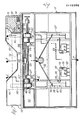
- a housing of a card reader has a front housing wall 1 and a rear housing wall 2, which are connected to one another by side walls 3 and 4 and intermediate walls 5 and 6.
- the upper wall 7 is only partially and broken away in Fig. 1, it is not shown in the other figures, it extends over the entire housing.
- a drive motor 8 is fixed, which drives a threaded spindle 9 via a gear, not shown, which is rotatably mounted in the intermediate walls 5 and 6.
- a guide rod 10 is also attached at a distance from the threaded spindle 9, on which a carriage 11 is guided, which has a magnetic head 12 at a distance from the guide rod 10 and on the side of the guide rod 10 facing away from the information head 12
- Rolls 13 and 14 carries.
- the roller 14 has on its periphery a bead 15, with which it engages in the thread base of the threaded spindle.
- the circumference of the roller 13 is cylindrical, it rolls on the space 16 between the thread base of the threaded spindle.
- the rollers 13 and 14 are pressed together by springs, not shown. If the threaded spindle 9 rotates, the carriage 11 is moved along the guide rod 10 by the roller 14.
- a pressure roller which presses it in the area of the card 17 inserted into the housing against the magnetic head 12 which slides over the magnetic track 18 in which the information is stored.
- an insertion slot 19 which is only slightly wider than the long side of the rectangular card 17 and whose height is only slightly larger than the thickness of such a card.
- the outer end of the insertion slot 19 is delimited by a housing part 20 which has a section 21 which projects beyond the rear card end when the card 17 is fully inserted into the slot 19 and which has a second section 22 via which the rear end 23 is completely card 17 inserted into the slot.
- the card 17 can be held at this rear end 23 when inserted and can be pulled out of the slot 19 again after the information exchange.
- the insertion movement of the card 17 in the slot 19 is limited by a stop rail 24 which is guided in the partition walls 5 and 6 in the insertion direction 25 of the card 17 against the action of a spring, not shown.
- the ends of the rail 24 passing through the intermediate walls 5 and 6 each carry a head 26 which carries an inclined surface 27 which, because the head 26 is screwed onto the ends of the rail 24 and therefore its position assumed when the head is screwed on, cannot be predicted, is designed as a cone.
- the insertion of the Card 17 delimiting rail 24 consists of a U-profile open towards the insertion side, into which the front end of the card inserted into the slot 19 enters, so that it cannot jump up or down even with strong impressions.
- Sensors 28 and 29 are displaceably mounted in the front housing wall and are pressed laterally into the insertion slot 19 by springs 30 and 31 at mutually opposite locations. These sensors 28 and 29 scan the size of the card between them.
- the housings of the switches 34 and 35 are fastened to the rear ends 32 and 33 of the sensors 28 and 29, which therefore also move in the axial direction of the sensors 28 and 29 when the sensors 28 and 29 are axially displaced when the card 17 is inserted into the insertion slot 19 move.
- the actuator 36 of the switches 34 and 35 has an inclined surface 37 which is formed by its bent tongue and which forms an angle of approximately 45 ° to the axial direction of the sensors 28, 29.
- the switch 34 is also moved outwards in the same direction, but the actuator 36 remains on the inclined surface 27 of the head part 26 due to the action of a spring acting on it the stop rail.
- the slight pivoting movement of the actuator 36 of the switch 34 does not yet actuate the switch 34. Only when the rail 24 is moved downwards in FIG. 3 by inserting the card the head 26 moves so far from the bent end of the actuator 36 of the switch 34 that the actuator 36 can perform its full pivoting movement under the action of the spring, not shown, and actuate the switch 34.
- the switches 34 and 35 at the two ends of the device are electrically connected in series, so that the circuit is only closed when both switches 34 and 35 are actuated.
- a slide 38 is slidably guided transversely to the direction of the insertion slot.
- a lever 39 is pivotally mounted on the slide, the other end of which is pivotably mounted on a lever 40 at a distance from its articulation 41 at 42.
- the lever 40 pivots in the first section of its displacement movement up to the position in which the magnetic head 12 reaches the card 17 under the action of the spring 43 to the extent that the carriage 11 extends removed from its rest position.
- the slider 38 moves to the left and then remains in a working position in which the lever end 42 also detaches from the carriage 11, so that the carriage 11 travels over the magnetic track 18 of the card 17 during the exchange of information, that is to say while the magnetic head 12 is moving , the lever 40 does not touch.
- the movement of locking members 45 and 46 is derived, which lock the card 17 in the position fully inserted into the insertion slot 19 during the exchange of information.
- the one ends of clamping parts 46 are mounted on the slide 38 so as to be pivotable about an axis 47.
- the parts 46 are also pivotally mounted about an axis 48 fixed to the housing, so that the ends 49 of the clamping parts 46 perform a pivoting movement about the axis 48 when the slide 38 moves.
- the axle bolts 47 engage in the clamping parts 46 with some play.
- the connecting line between the ends 49 and the axis 48 forms an angle of approximately 150 ° with the connecting line of the axes 47 and 48 and the distance of the ends 49 from the axis 48 is substantially smaller than the distance between the axes 47 and 48.
- the ends 49 have a curve, to which the edge of the clamping part 46 then extends obliquely upwards, so that even with a relatively small movement of the slide 38 to the right, the parts 46 completely release the slot 19.
- Fig. 2 the parts 46 are drawn in their engaged position, in which they press an inserted into the slot 19, not shown card against a table-like base 50.
- the slider 38 also has a slot guide 51, the central part 52 of which runs obliquely.
- the inner end 53 of a pivotably mounted rod 54 engages in this slot guide and is pivotably mounted about the axis 55 of a bearing disc 56 mounted in the housing wall 1 (not shown in FIG. 4).
- the end 57 facing away from the end 53 of the lever 54 engages in a recess in a locking pin 45.
- the locking pin 45 When pivoting the rod 54 in the direction of the double arrow 58, the locking pin 45 therefore moves in the direction of the double arrow 59.
- This locking pin 45 is displaceably mounted transversely to the plane of the insertion slot 19 in the housing section 21, in its upper position in FIG. 4 it engages behind the rear end of the card 17 in the insertion slot 19 and locks the card 17 in this position.
- the magnetic head 12 is then guided by driving the threaded spindle 9 over the track 18 applied to the card 17, in which the information is stored.
- the information is exchanged during this movement and the magnetic head reads the stored information or stores information in track 18.
- the carriage runs back and then takes the end 42 of the lever 40 into the rest position in the last movement section.
- the slide 38 is shifted to the right, the ends 49 of the links 46 are pivoted out of the insertion slot 19 and the pin 45 is moved downward in the housing part 21, so that it no longer projects into the insertion slot 19.
- the card 17 can be gripped at the end 23 protruding from the housing section 22 and pulled out again from the slot 19, the stop rail 24 as well as the switches 34 and 35 and the sensors 28 and 29 move back into their starting position.
- the drive of the spindle 9 has already been switched off by a circuit, not shown, after the carriage 11 has reached its rest position at the left end of the spindle.
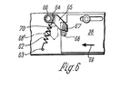
- a spring 62 is provided instead of the spring 43, one end of which is in turn attached to a bolt 63 of the housing and the other end at 64 engages a tab 65 which is about a bolt fixed to the housing 66 is pivotally mounted.
- the free end of the tab 65 has a surface 67 which rests on a roller 68 which is rotatably mounted on the slide 38.
- the tension spring 62 endeavors to pivot the tab 65 clockwise.
- the head 11 When moving from the working position to the rest position, the head 11 engages the lever transmission 42, 40, 44, 39, which is designed so that it increases the force exerted by the carriage 11 on the lever end 42 after leaving the card.
- the slide 38 is moved back to its starting position against the force exerted by the surface 70 on the roller 68 and by overcoming the frictional resistance created by the clamping of the parts 46 on the card 17, that is to say the self-locking of the clamping of these parts is released.
- 110 denotes a front part and 111 a housing part.
- the end part 110 is provided with an indentation which extends on the one hand in the horizontal direction, as denoted by 112, but on the other hand also in the vertical direction, as is shown in FIG. 8 is designated by 113.
- the indentation ends in a slot 123 into which a card 114 can be inserted along an insertion path 115, 116.
- the card 114 is drawn in continuously in a position in which it is fully inserted into the device. As can be seen in the partial section at the top right in FIG. 7, the card 114 meets a first one on its way along the insertion path 115, 116 when it is first inserted into the front part 110 Slider 117 which, when the card 114 is not inserted, projects beyond the insertion path 115 into the slot 123.
- the first slide 117 as shown in FIG. 7, is deflected to the right against the force of a spring 118, which is supported on a wall 119 of the front part 110.
- the first slide 117 moves along a guide 120 and a pin 122 of a switch not shown in FIG. 7, which extends into a recess 121 in the first slide 117, is deflected. With this mechanism it is therefore possible to recognize the insertion of the card 114 into the slot 123 along the insertion path 115, 116.
- a motor 125 is briefly connected to the supply voltage, for example via the series connection of two switches mentioned.
- the motor 125 rotates a shaft 126 which is mounted in bearing blocks 127, 128.
- the shaft 126 carries a first one Eccentric pair 130, 131.
- This eccentric pair 130, 131 actuates a first lock 132 in the manner shown in more detail below, which in the embodiment shown in the figure has the form of a sheet which slits the slot 123 when the card 114 is not inserted in the region of the Entry of the slot 123 blocked in the housing part 111.
- This first lock thus prevents possible manipulation of the device, since the slot 123 is closed when the card is not inserted. Only when, as described, a card 114 with the correct width is inserted into the slot 123, does the first lock 132 open the way for the card 114 into the housing part 111 by briefly actuating the motor 125 and rotating the eccentrics 130, 131.
- the card 114 can be inserted into the housing part 111 along the insertion path 115, 116 and encounters second sliders 136, 137 there, which are arranged displaceably in the housing part 111 in the manner described in detail below.
- the second slides 136, 137 actuate switches 138, 139, which can also be in series, for example, so that actuation of both switches 138, 139 by a card of the correct size leads to the closing of a circuit.
- This circuit actuates the motor 125 again briefly, so that now a further, second pair of eccentrics 140, 141, which is also arranged on the shaft 126, takes effect.
- the second pair of eccentrics 140, 141 actuates a second lock in the form of two hooks 142, 143 which reach behind the back of the card 114 and fix it against pulling out. In this way, the card 114 is held during the data exchange, so that a reading or writing unit 165 can carry out the data exchange from the device to the card 114 without being disturbed.
- the first lock 132 consists of a sheet metal part which is bevelled on the upper side.
- a first tab 145 is attached to the center of the top of the first lock 132.
- a spring wire 146 is arranged below the first tab 145 and engages in recesses 147, 148 which are formed on the bearing blocks 127, 128.
- a second tab 150 and a third tab 151 are integrally formed on the lock 132. These tabs 150, 151 are operatively connected to the first pair of eccentrics 130, 131.
- the eccentric 130 is shown in a position into which it was rotated by the motor 125 after actuation of the first slide 117 by the card 114. The eccentric 130 does not engage the tab 150 in this position, so that the first lock 132, held elastically by the spring wire 146, can sag downward in the housing part 111. In this position, the first lock 132, as can be seen from FIGS. 8 and 9, clears the way for the card 114.
- the first eccentric 130 is rotated clockwise and consequently, as can be seen from FIG. 8, engages the tab 150.
- the eccentric 130 then pushes the tab 150 upward, so that the first lock 132 blocks the opening of the slot 123 in the housing part 111.
- the card 114 After the card 114 enters the housing part 111, it initially encounters a hold-down device 170, which is held by a spring 171 which is supported against a cover 172 of the housing part 111. At the end facing the card entry, the hold-down device 170 is provided with a first bevel 173, so that the card 114, even if it is slightly bent at the edges, safely reaches below the hold-down device 170. After passing through the hold-down device 170 and the read / write unit 165, the card 114 encounters the second sliders 136, 137, which are provided with a second bevel 174 at their end facing the card 114.
- the card 114 runs on a table 175 which forms an intermediate floor of the housing part 171 until it abuts a stop 176 of the table 175.
- a floor 177 then extends from the stop 176 to the rear wall of the housing part 111, in which the second slides 136, 137 run when the card 114 is inserted.
- FIG. 12a shows the second slide 136 in a side view; the figures 12b and 12c show sections along the line DD 'and EE' of Fig. 12a.
- the second slide 136 has a profiled, plier-like shape, the upper and lower parts being held together by a common body 180.
- the upper part consists of a flange 181, which ends laterally in spring-shaped flanges 182, 183.
- the spring-like flanges 182, 183 terminate in a stop 184 on the left end face in FIG. 12a.
- the pliers-like shape of the second slide 136 is formed by an incision 185 running in the longitudinal direction. Below the incision 185 is the lower part of the second slide 136, which, immediately adjacent to the incision 185, ends in two spring-like flanges 186, 187, which form a stop 188 at their right end in FIG. 12a. In the lower area, the second slide 136 then runs out into a central web 193 which has an opening 194 for receiving a spring 195.
- the second slide 136 When the card 114 is not inserted, the second slide 136 is in the position not shown in FIG. 11.
- the incision 185 then encompasses the table 175, the spring-like flanges 182, 183 sliding on its upper side and the spring-like flanges 186, 187 on its lower side. If the card 114 is now inserted into the slot 123, after passing through the hold-down device 170 and the read / write unit 165 it comes into engagement with the stop 184 and pushes the second slide 136 in FIG. 11 to the right.
- the guide of the second slide 136 is thereby caused by the spring-like flanges 182, 183 which run in corresponding grooves in the bottom 177. During this displacement of the second slide 136, 137, the spring 195 is deflected.
- the switch 138 consists of a switch housing 190 to which a switching arm 191 is pivotably articulated.
- connections 192 emerge from the switch housing 190.
- An extension of the switching arm 191 protrudes into an opening 196 of the guide for the second slide 136, 137. If the second slide 136 is now moved further and further (downward in FIG. 7, to the right in FIG. 11), the stop 188 finally arrives of the spring-like flange 187 engages with the switch arm 191 and thus actuates the switch 138 before the card 114 abuts the stop 176.
Landscapes
- Engineering & Computer Science (AREA)
- Physics & Mathematics (AREA)
- General Physics & Mathematics (AREA)
- Theoretical Computer Science (AREA)
- Artificial Intelligence (AREA)
- Computer Vision & Pattern Recognition (AREA)
- Lock And Its Accessories (AREA)
Priority Applications (1)
| Application Number | Priority Date | Filing Date | Title |
|---|---|---|---|
| EP83103542A EP0122302A1 (fr) | 1983-04-13 | 1983-04-13 | Dispositif pour la lecture et/ou pour l'enregistrement des informations d'un support d'informations en forme d'une carte |
Applications Claiming Priority (1)
| Application Number | Priority Date | Filing Date | Title |
|---|---|---|---|
| EP83103542A EP0122302A1 (fr) | 1983-04-13 | 1983-04-13 | Dispositif pour la lecture et/ou pour l'enregistrement des informations d'un support d'informations en forme d'une carte |
Publications (1)
| Publication Number | Publication Date |
|---|---|
| EP0122302A1 true EP0122302A1 (fr) | 1984-10-24 |
Family
ID=8190404
Family Applications (1)
| Application Number | Title | Priority Date | Filing Date |
|---|---|---|---|
| EP83103542A Withdrawn EP0122302A1 (fr) | 1983-04-13 | 1983-04-13 | Dispositif pour la lecture et/ou pour l'enregistrement des informations d'un support d'informations en forme d'une carte |
Country Status (1)
| Country | Link |
|---|---|
| EP (1) | EP0122302A1 (fr) |
Cited By (3)
| Publication number | Priority date | Publication date | Assignee | Title |
|---|---|---|---|---|
| DE3929141A1 (de) * | 1989-09-02 | 1991-03-14 | Hopt & Schuler Ddm | Kartenkontrollvorrichtung, insbesondere fuer kartenleser |
| WO1991012595A1 (fr) * | 1990-02-13 | 1991-08-22 | Bilgrey Samson & Company Limited | Lecteur de cartes |
| FR2661528A1 (fr) * | 1990-04-30 | 1991-10-31 | Sagem | Dispositif de securite pour appareil lecteur d'informations. |
Citations (8)
| Publication number | Priority date | Publication date | Assignee | Title |
|---|---|---|---|---|
| US3489869A (en) * | 1968-05-16 | 1970-01-13 | Gen Electric | Switch mechanism for expandable track device with a switch actuator also serving as a stop means |
| CH589332A5 (en) * | 1975-01-08 | 1977-06-30 | Omron Tateisi Electronics Co | Input control device for coding cards - for use in identification system, has three parts, one of which has passage for cards |
| FR2356206A1 (fr) * | 1976-06-25 | 1978-01-20 | Siemens Ag | Appareil de lecture ou d'ecriture pour cartes pourvues d'un support de donnees magnetique |
| US4087680A (en) * | 1977-04-22 | 1978-05-02 | Burroughs Corporation | Semiautomatic credit card information handling apparatus |
| US4128237A (en) * | 1976-07-06 | 1978-12-05 | Relhor S.A. | Card input device for precision punching of cards |
| US4151564A (en) * | 1977-12-02 | 1979-04-24 | Burroughs Corporation | Modular, semiautomatic credit card reader/writer apparatus |
| US4197988A (en) * | 1977-12-02 | 1980-04-15 | The Vendo Company | Apparatus for reading and writing data onto a magnetic stripe and in an arcuate path |
| US4309601A (en) * | 1980-08-25 | 1982-01-05 | Ncr Canada Ltd. - Ncr Canada Ltee | Moving head reader mechanism |
-
1983
- 1983-04-13 EP EP83103542A patent/EP0122302A1/fr not_active Withdrawn
Patent Citations (8)
| Publication number | Priority date | Publication date | Assignee | Title |
|---|---|---|---|---|
| US3489869A (en) * | 1968-05-16 | 1970-01-13 | Gen Electric | Switch mechanism for expandable track device with a switch actuator also serving as a stop means |
| CH589332A5 (en) * | 1975-01-08 | 1977-06-30 | Omron Tateisi Electronics Co | Input control device for coding cards - for use in identification system, has three parts, one of which has passage for cards |
| FR2356206A1 (fr) * | 1976-06-25 | 1978-01-20 | Siemens Ag | Appareil de lecture ou d'ecriture pour cartes pourvues d'un support de donnees magnetique |
| US4128237A (en) * | 1976-07-06 | 1978-12-05 | Relhor S.A. | Card input device for precision punching of cards |
| US4087680A (en) * | 1977-04-22 | 1978-05-02 | Burroughs Corporation | Semiautomatic credit card information handling apparatus |
| US4151564A (en) * | 1977-12-02 | 1979-04-24 | Burroughs Corporation | Modular, semiautomatic credit card reader/writer apparatus |
| US4197988A (en) * | 1977-12-02 | 1980-04-15 | The Vendo Company | Apparatus for reading and writing data onto a magnetic stripe and in an arcuate path |
| US4309601A (en) * | 1980-08-25 | 1982-01-05 | Ncr Canada Ltd. - Ncr Canada Ltee | Moving head reader mechanism |
Non-Patent Citations (1)
| Title |
|---|
| IBM TECHNICAL DISCLOSURE BULLETIN, Band 9, Nr. 7, Dezember 1966, Seiten 770-771, New York (USA); * |
Cited By (3)
| Publication number | Priority date | Publication date | Assignee | Title |
|---|---|---|---|---|
| DE3929141A1 (de) * | 1989-09-02 | 1991-03-14 | Hopt & Schuler Ddm | Kartenkontrollvorrichtung, insbesondere fuer kartenleser |
| WO1991012595A1 (fr) * | 1990-02-13 | 1991-08-22 | Bilgrey Samson & Company Limited | Lecteur de cartes |
| FR2661528A1 (fr) * | 1990-04-30 | 1991-10-31 | Sagem | Dispositif de securite pour appareil lecteur d'informations. |
Similar Documents
| Publication | Publication Date | Title |
|---|---|---|
| EP0414668B1 (fr) | Distributeur automatique de vente et de location, notamment pour videocassettes | |
| DE68929147T2 (de) | Kartenlesegerät mit Verriegelung | |
| DE2638075C3 (fr) | ||
| DE2456255A1 (de) | Kartenbearbeitungsvorrichtung | |
| DE2307193A1 (de) | Eingabekontrolle fuer dokumente zur benutzung von automaten | |
| DE2115171A1 (de) | F ahrkarten-Bearbeitungs vorrichtung | |
| EP0490049A2 (fr) | Récipient pour cassettes à bande magnétique | |
| EP0281108B1 (fr) | Distributeur d'argent | |
| DE4210104A1 (de) | Magnetkartenleser mit einer kopfumkehrfunktion | |
| EP1570416A1 (fr) | Logement pour carte a puce equipe d'un ejecteur et d'au moins un bras de verrouillage relie a ce dernier | |
| DE2618439B1 (de) | Transporteinrichtung fuer die auswertung von identifizierungskarten | |
| DE3516460A1 (de) | Einrichtung zur voruebergehenden speicherung von belegen | |
| DE69623189T2 (de) | Chipkartenabtaster | |
| EP0628934A1 (fr) | Carte pour serrure de consigne | |
| EP1623362B1 (fr) | Dispositif de reception de carte | |
| DE3145705C2 (de) | Vorrichtung zum Auslesen und/oder Einspeichern einer Information aus beziehungsweise in eine einen Speicher für die Information aufweisende, während des Informationsaustausches feststehende Karte | |
| DE3313355C2 (fr) | ||
| DE2411182A1 (de) | Kartenkassette | |
| DE2104290C3 (de) | Vorrichtung zum Erfassen der Form der Vorderkante eines entlang einer vorgegebenen Bahn bewegten Gegenstandes | |
| EP0882273B1 (fr) | Lecteur hybride en trois dimensions surveille (lecteur maresch) | |
| DE69617535T2 (de) | Türzusammenbau für Kassettenhandhabungsvorrichtung | |
| DE3153177C1 (en) | Device for reading-out and/or storing an information from or respectively in a card exhibiting a memory for the information and being stationary during the exchange of information | |
| DE3879152T2 (de) | Aufnahme- und wiedergabevorrichtung. | |
| CH646806A5 (en) | Lock with a locking function to be actuated after coin insertion | |
| EP0280881A2 (fr) | Unité de distribution pour documents de valeur |
Legal Events
| Date | Code | Title | Description |
|---|---|---|---|
| PUAI | Public reference made under article 153(3) epc to a published international application that has entered the european phase |
Free format text: ORIGINAL CODE: 0009012 |
|
| AK | Designated contracting states |
Designated state(s): FR GB IT NL |
|
| 17P | Request for examination filed |
Effective date: 19850313 |
|
| 17Q | First examination report despatched |
Effective date: 19860130 |
|
| R17C | First examination report despatched (corrected) |
Effective date: 19870203 |
|
| RAP1 | Party data changed (applicant data changed or rights of an application transferred) |
Owner name: RINAS GERAETETECHNIK GMBH |
|
| STAA | Information on the status of an ep patent application or granted ep patent |
Free format text: STATUS: THE APPLICATION IS DEEMED TO BE WITHDRAWN |
|
| 18D | Application deemed to be withdrawn |
Effective date: 19880705 |
|
| RIN1 | Information on inventor provided before grant (corrected) |
Inventor name: BIRKLE, GEBHARD Inventor name: RAPP, HANS-JOCHEN Inventor name: HOPT, RUDOLF |