EP0122467A2 - Système d'enregistrement et de reproduction d'information d'images - Google Patents
Système d'enregistrement et de reproduction d'information d'images Download PDFInfo
- Publication number
- EP0122467A2 EP0122467A2 EP84102799A EP84102799A EP0122467A2 EP 0122467 A2 EP0122467 A2 EP 0122467A2 EP 84102799 A EP84102799 A EP 84102799A EP 84102799 A EP84102799 A EP 84102799A EP 0122467 A2 EP0122467 A2 EP 0122467A2
- Authority
- EP
- European Patent Office
- Prior art keywords
- image information
- retrieving
- information
- optical disk
- retrieving data
- Prior art date
- Legal status (The legal status is an assumption and is not a legal conclusion. Google has not performed a legal analysis and makes no representation as to the accuracy of the status listed.)
- Granted
Links
Images



Classifications
-
- G—PHYSICS
- G11—INFORMATION STORAGE
- G11B—INFORMATION STORAGE BASED ON RELATIVE MOVEMENT BETWEEN RECORD CARRIER AND TRANSDUCER
- G11B17/00—Guiding record carriers not specifically of filamentary or web form, or of supports therefor
- G11B17/005—Programmed access to indexed parts of tracks of operating discs, by guiding the disc
-
- G—PHYSICS
- G06—COMPUTING OR CALCULATING; COUNTING
- G06F—ELECTRIC DIGITAL DATA PROCESSING
- G06F16/00—Information retrieval; Database structures therefor; File system structures therefor
- G06F16/90—Details of database functions independent of the retrieved data types
- G06F16/901—Indexing; Data structures therefor; Storage structures
- G06F16/9017—Indexing; Data structures therefor; Storage structures using directory or table look-up
-
- G—PHYSICS
- G11—INFORMATION STORAGE
- G11B—INFORMATION STORAGE BASED ON RELATIVE MOVEMENT BETWEEN RECORD CARRIER AND TRANSDUCER
- G11B20/00—Signal processing not specific to the method of recording or reproducing; Circuits therefor
- G11B20/10—Digital recording or reproducing
- G11B20/12—Formatting, e.g. arrangement of data block or words on the record carriers
- G11B20/1217—Formatting, e.g. arrangement of data block or words on the record carriers on discs
-
- G—PHYSICS
- G11—INFORMATION STORAGE
- G11B—INFORMATION STORAGE BASED ON RELATIVE MOVEMENT BETWEEN RECORD CARRIER AND TRANSDUCER
- G11B27/00—Editing; Indexing; Addressing; Timing or synchronising; Monitoring; Measuring tape travel
- G11B27/10—Indexing; Addressing; Timing or synchronising; Measuring tape travel
- G11B27/19—Indexing; Addressing; Timing or synchronising; Measuring tape travel by using information detectable on the record carrier
-
- G—PHYSICS
- G11—INFORMATION STORAGE
- G11B—INFORMATION STORAGE BASED ON RELATIVE MOVEMENT BETWEEN RECORD CARRIER AND TRANSDUCER
- G11B7/00—Recording or reproducing by optical means, e.g. recording using a thermal beam of optical radiation by modifying optical properties or the physical structure, reproducing using an optical beam at lower power by sensing optical properties; Record carriers therefor
-
- G—PHYSICS
- G11—INFORMATION STORAGE
- G11B—INFORMATION STORAGE BASED ON RELATIVE MOVEMENT BETWEEN RECORD CARRIER AND TRANSDUCER
- G11B2220/00—Record carriers by type
- G11B2220/20—Disc-shaped record carriers
- G11B2220/25—Disc-shaped record carriers characterised in that the disc is based on a specific recording technology
- G11B2220/2508—Magnetic discs
-
- G—PHYSICS
- G11—INFORMATION STORAGE
- G11B—INFORMATION STORAGE BASED ON RELATIVE MOVEMENT BETWEEN RECORD CARRIER AND TRANSDUCER
- G11B2220/00—Record carriers by type
- G11B2220/20—Disc-shaped record carriers
- G11B2220/25—Disc-shaped record carriers characterised in that the disc is based on a specific recording technology
- G11B2220/2537—Optical discs
Definitions
- the present invention relates to an image information registering/retrieving system, and more particularly to an image information registering/retrieving system of the type in which a plurality of image information on documents is successively registered on an optical disk and a plurality of retrieving data corresponding to the image information is stored on a magnetic disk, and any desired image information is read out using a retrieving data associated with the desired image information.
- a plurality of image information is obtained by optically scanning documents and registering on an optical disk.
- a plurality of retrieving data for retrieving the image information is stored on a magnetic disk.
- a control unit controls the optical disk and the magnetic disk. Selected retrieving data in the magnetic disk is read out and applied to the control unit. Using the selected retrieving data, the control unit specifies that location of the optical disk on which the desired information is registered, and reads out the desired image information thereform.
- the read-out image information is visualized by a CRT display or recorded by a recording device.
- the image information registering/retrieving system having the above described functions requires a magnetic memory device for driving the magnetic disk.
- the magnetic disk wears down and possibly loses its function. In such a case, it is not possible to read out the retrieving data therefrom, resulting in that the functions of the image information registering/retrieving system per se stop.
- the prior system is provided with an auxiliary magnetic memory device.
- the magnetic memory device may be designed such that the defective magnetic disk is replaced with a new disk. This approach indeed succeeds in restricting the increase of cost to some degree. Nevertheless, it takes a long time to store the retrieving data onto the new magnetic disk. In this respect, this approach is not practical.
- a more serious disadvantage of the approach is that it is very difficult to keep the predetermined correspondence between the retrieving data on the magnetic disk and the image information registered in the optical disk.
- an object of the present invention is to provide an image information registering/retrieving sysfem in which the optical disk (first storing medium) is registered with a plurality of image information and a plurality of retrieving data with a corresponding relationship therebetween, and, when the magnetic disk loses its function and is replaced by a new magnetic disk, the retrieving data registered on the optical disk is copied on the new magnetic disk.
- an image information registering/retrieving system comprises a first information-storing medium on which a plurality of image information and a plurality of retrieving data for reproducing the image information are registered, each of the retrieving data being in correspondence with the corresponding image information, a second information-storing medium on which the plurality of retrieving data is stored, and means for controlling the first information-storing medium and the second information-storing medium in such a manner that the plurality of retrieving data registered on the first information-storing medium is copied onto another second information-storing medium when the second information-storing medium loses its function and is replaced by the another second information-storing medium.
- the image information registering/retrieving system includes a main control section 11.
- a CPU.12 is coupled with buses 5 and 6;
- a main memory 13 is connected to the bus 5;
- a compression/expansion circuit 15 is connected to the buses 5 and 6, the circuit 15 compresses image information and expands the compressed one into an unexpanded state by employing the modified Hoffman method;
- a pattern generator 16 is connected to the buses 5 and 6 to store various types of characters and symbols;
- a RAM (random access memory) 18 is connected to the buses 5 and 6;
- a buffer memory 29 for temporarily storing information is connected to the buses 5 and 6; and
- a display interface circuit 17 is connected to the buses 5 and 6.
- the buses 5 and 6 are coupled, at the other ends, with an external device (not shown).
- An optical scanning device 20 is coupled with the image information buffer memory 29.
- the ⁇ device 20 two-dimensionally scans the documents 21 sheet-by-sheet with a laser beam to obtain the image information on the documents, converts the image information into corresponding electrical signals, and loads the electrical signals into the image information storing buffer memory 29.
- An optical disk 19 as a first information-storing disk is used to register pieces of information read out from the documents 21 and the data for retrieving the image information thereonto and to reproduce the registered image information and the registered retrieving data therefrom. Registration and reproduction on or from the optical disk 19 are controlled by the optical disk control device 22 which is connected to the buses 5, 6 and coupled to the optical disk 19.
- a CR T (cathode ray tube) display 24 Connected to the output terminal of the display interface circuit 17 is a CR T (cathode ray tube) display 24.
- the CRT display 24 visualizes the image information which has been optically obtained from the documents, and which has been appropriately controlled and processed by the main control section 11.
- the CRT display 24 displays the image information and the retrieving data, which are read out from the optical disk 19 under the control of the optical disk control device 22.
- the display interface circuit 17 and the CRT display 24 cooperate to form a display device.
- a magnetic control device 27 is coupled with the buses 5 and 6.
- a keyboard 23 is connected to the bus 5. The keyboard 23 is used for inputting to the main control section 11 a retrieving code for reading out image information which corresponds to the retrieving code and required instruction data.
- a recording device 22 connected to the buses 5, 6 receives, through the main control section 11, the image information on the documents 21 obtained by the optical scanning device 20 and records the image information in the form of hard copy.
- the recording device 22 also receives, through the main control section, the image information and the retrieving data read out from the optical disk 19 by the optical disk control device 22 and records them in the form of hard copy.
- the optical disk 19, as shown in Fig. 2, contains a circular disk made of glass or plastic which is coated with tellurium or bismuth.
- a hole centered in the disk is provided for inserting a shaft for rotating the disk in the direction of the arrow indicated.
- the hole has a cut-away portion 19 1 to ensure that the disk is in the proper reference position.
- the surface of the optical disk 19 is segmented into a plurality of sectors OS - 31S which are numbered counterclockwise from the reference position as viewed in the drawing.
- the surface is further segmented into 100 registering trucks OT - 100T as numbered in the radial direction. Actually, these trucks are formed in a spiral fashion, but represented as coaxial rings in the diagram.
- the first image information (I-INF), the second image information (I-INF) and so on are successively registered in the sectors on the truck marked OT, the (I-INFs) being numbered counterclockwise, i.e. in the direction of the arrow 19 2 , from the reference axis.
- the first retrieving data (R - D) and the second retrieving data (R - D), and so on are successively registered in the sectors on the truck marked 100T, the (R - Ds) being numbered clockwise, i.e. in the direction of arrow 19 3 , from the reference axis.
- Fig. 4 there is shown the radially elongated recording area of the optical disk 19.
- Fig. 4 typically illustrates how image information and retrieving data are allocated in the memory area of the optical disk 19.
- the first (I-INF) occupies the Od to 10th sectors in the Od truck
- the second (I-INF) occupies the llth to 20th sectors in the Od truck.
- the 1st (R - D) is registered in the 29th to 31st sectors in the 100th truck
- the 2nd (R - D) in the 26th to 28th sectors in the 100th truck.
- the retrieving data (R - D) is composed of a start (ST) field, a direct number (DN) field representing, for example, a serial number assigned to the image information, a retrieving code (R - C) section, a retrieving address (R - A) section, and an end (END) field.
- the retrieving code section contains a sex distinction field, an employee number field, and a name field.
- the address section contains a field L representing the number L of sectors occupied by the image information as denoted by the retrieving code (R - C).
- T-ADR truck address
- S-ADR ctor address
- SIZE image size
- the magnetic disk 28 is composed of a first storing area 28a for storing the retrieving data, a second storing area 28b in which an address data NIIA (next image information address) is stored, the NIIA representing an initial truck number and an initial sector number in which the start portion of image information next to the image information corresponding to the retrieving code (R - C) is stored, and a third storing area 28c in which an address data NRIA (next retrieving data initial address) is stored, the NRIA representing an initial truck number and an initial sector number in which the start portion of retrieving data next to the retrieving code (R - C) is stored.
- NIIA next image information address
- NRIA non retrieving data initial address
- NIIA represents the address (0: 21) (Od truck: 21th sector) which is next to the last address (0: 20) of the second (I-INF) and the top address (0: 21) of the third (I-INF).
- NRIA represents the address (100; 25) (100th truck: 25th sector) which is next to the last address (100: 26) of the 2nd (R-D) and the top address (100: 25) of the 3rd (R-D).
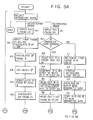
- FIG. 5A and 5 B The operation of an image information registering/retrieving system thus arranged will be described referring to flow charts shown in Figs. 5A and 5 B .
- the main control section 11 is driven and the keyboard 23 is operated to select the desired operation mode. It is assumed now that a registering mode is selected. In this mode, the first (I-INF) (image information), the second (I-INF), etc. and the first (R - D) (retrieving data), the second (R - D), etc. are registered onto the sectors of a truck (for example, Od truck) on the optical disk 19, as shown in Fig. 4.
- a truck for example, Od truck
- step AI an operator operates the keyboard 23 to enter the first (R - C) (retrieving code shown in Fig. 3) into the main control section 11.
- step A2 the CPU 12, upon receipt of the (R - C), controls the optical scanning device 20 to scan one of the documents 21 to obtain the first (I-INF) from the document and to input the first (I-INF) into the main control section 11.
- step A2 the length 1 of the first (I-INF) is calculated.
- the CPU 12 calculates 1 * using the length 1.
- the 1* indicates the number of trucks and the sectors necessary for registering the image information having the length l.
- HA is calculated on the basis of N II A + I * .
- the NI I A indicates the top address of the 1st (I-INF) and the HA represents the top address of the second (I-INF).
- the retrieving data m is constructed by coupling the 1 * obtained in step A3, the NIIA in the 1st (I-INF), and the 1 obtained in step A2.
- m * is calcualted using m[lst (R - D)] obtained in step A5.
- the symbol m * represents the number of trucks and sectors necessary for registering the first (R - D) with a length of m.
- step A7 the head address HA of the second (I-INF) obtained in step A4 is compared with (NRIA - m * ), where NRIA is the top address of the second (R - D).
- step A7 when HA ⁇ (NIRA - m * ), step A8 is executed.
- HA ⁇ (NRIA - m * ) the CRT display 24 indicates that no space for registering is left on the optical disk 19.
- step A8 the first (I-INF) is registered using the address NIIA as a top address.
- step 9 the address NIIA of the second (I-INF) is calculated using the address HA of the second (I-INF) obtained in step A4.
- step A10 the first (R - D) is registered using the address NRIA as a top address.
- NRIA 2 is obtained using (NRIA l - m*).
- NRIA 1 indicates the top address of the first (R - D ).
- N R I A2 indicates the top address of the second ( R - D ), and m * indicates the data obtained in step A6.
- the first (R - D) is stored into the retrieving data storing area 28a of the magnetic disk 28. For registering the first (I-INF), the second (I-INF), etc. on the optical disk 19 and for storing the first (R - D), the second (R - D), etc. on the mangetic disk 28, it is sufficient that steps Al to A12 be repeated.
- the retrieval mode will be described referring to steps Bl to B9, assuming that this mode is selected by operating the keyboard 23. In this case, it is assumed that the second (I-INF) which has been registered on the optical disk 19 is retrieved.
- step Bl a second (R - C) (retrieving code) is keyed in on the keyboard 23.
- step B2 it is judged whether the operation of the magnetic disk 28 is normal or not. When it is normal (YES), the operation advances to step B3.
- step B3 the first (R - C), the second (R - C), and so on, are successively read out from the memory area 28a of the magnetic disk 28, and are loaded into the RAM 18.
- step B4 the (R - Cs) read out from the RAM 18 are successively compared with the (R - C) already input in step Bl.
- the second (R - C) of the second (R - D) is input in step Bl.
- step B5 the second (R - A) (retrieving address) corresponding to the second (R - C) is read out from the areas 28b and 28c of the magnetic disk 28.
- step B 6 with the second ( R - A), the second (I-INF) is read out from the optical disk 19 and loaded into the image information buffer memory 29. Since the second ( I -IN F ) contains compressed image information, the second (I-INF) must be expanded by the compression/expansion circuit 15 and loaded into the page buffer memory 14. This operation is done in step B7. In step B8, the second (I-INF) is expanded and transmitted to the display interface circuit 17.
- step B9 the expanded second (I-INF) is displayed on the CRT display 24. Subsequently, through steps similar to the above, a desired (I-INF) is read out from the optical disk 19, displayed on the CRT display 24 or recorded by the recording device 25.
- step Cl the image information is retrieved using the (R - Ds) registered on the optical disk 19.
- the CPU 12 reads out the (R - Ds) one-by-one from the optical disk 19 which is controlled by the optical disk control device 22, and stores the output into the RAM 18.
- step C2 the (R - C) from the keyboard 23 i-s successively compared with the (R - Cs) read out from the RAM 18 to find the (R - C) from the keyboard 23 which are coincident with each other.
- the coincident (R - C) is used as an address to read out the image information as specified by the coincident address from the optical disk 19.
- the read out image information is either displayed by the CRT display 24, or is recorded by the recording device 25.
- step C3 the defective magnetic disk 28 is replaced with a new magnetic disk.
- step C4 the (R - Ds ) of the optical disk 19 are-copied onto the new magnetic disk.
- the CPU 12 controls the optical disk control device 22 to sequentially read out the ( R - Ds) from the optical disk 19 and to store them in the area 28a of the magnetic disk 28. In this case, every time a (R - D) is read out from the optical disk 19, the addresses NIIA and NRIA corresponding to those (R - D s) are counted to provide the corresponding memory locations in the memory areas 28b and 28c of the NII A and NRIA.
- the image information may be registered on the optical disk 19 from the peripheral side to the center, and the retrieving data may be registered from the center to the peripheral side.
Landscapes
- Engineering & Computer Science (AREA)
- Databases & Information Systems (AREA)
- Theoretical Computer Science (AREA)
- Signal Processing (AREA)
- Software Systems (AREA)
- Data Mining & Analysis (AREA)
- Physics & Mathematics (AREA)
- General Engineering & Computer Science (AREA)
- General Physics & Mathematics (AREA)
- Information Retrieval, Db Structures And Fs Structures Therefor (AREA)
- Management Or Editing Of Information On Record Carriers (AREA)
Applications Claiming Priority (2)
| Application Number | Priority Date | Filing Date | Title |
|---|---|---|---|
| JP54331/83 | 1983-03-30 | ||
| JP58054331A JPS59178879A (ja) | 1983-03-30 | 1983-03-30 | 画像情報記憶検索装置 |
Publications (3)
| Publication Number | Publication Date |
|---|---|
| EP0122467A2 true EP0122467A2 (fr) | 1984-10-24 |
| EP0122467A3 EP0122467A3 (en) | 1987-11-25 |
| EP0122467B1 EP0122467B1 (fr) | 1991-12-18 |
Family
ID=12967608
Family Applications (1)
| Application Number | Title | Priority Date | Filing Date |
|---|---|---|---|
| EP84102799A Expired - Lifetime EP0122467B1 (fr) | 1983-03-30 | 1984-03-14 | Système d'enregistrement et de reproduction d'information d'images |
Country Status (4)
| Country | Link |
|---|---|
| US (1) | US4544956A (fr) |
| EP (1) | EP0122467B1 (fr) |
| JP (1) | JPS59178879A (fr) |
| DE (1) | DE3485351D1 (fr) |
Cited By (8)
| Publication number | Priority date | Publication date | Assignee | Title |
|---|---|---|---|---|
| DE3637767A1 (de) * | 1985-11-06 | 1987-05-07 | Canon Kk | Dateisystem |
| EP0333165A3 (en) * | 1988-03-16 | 1990-09-19 | Matsushita Electric Industrial Co., Ltd. | System and method for managing recording areas on writable type optical disk |
| EP0477876A3 (en) * | 1990-09-27 | 1992-05-27 | Casio Computer Company Limited | Digital recorder |
| EP0282997A3 (fr) * | 1987-03-18 | 1993-03-03 | Kabushiki Kaisha Toshiba | Appareil pour fichiers électroniques, capables de mémoriser de fichiers dans une mémoire optique |
| US5355355A (en) * | 1987-03-18 | 1994-10-11 | Kabushiki Kaisha Toshiba | Electronic file apparatus capable of storing code data and image data into optical memory |
| US5519684A (en) * | 1990-05-14 | 1996-05-21 | Casio Computer Co., Ltd. | Digital recorder for processing in parallel data stored in multiple tracks |
| US5581530A (en) * | 1990-09-06 | 1996-12-03 | Casio Computer Co., Ltd. | Digital recorder for processing of parallel data stored in multiple tracks and using cross-fade processing |
| US5974015A (en) * | 1990-05-14 | 1999-10-26 | Casio Computer Co., Ltd. | Digital recorder |
Families Citing this family (14)
| Publication number | Priority date | Publication date | Assignee | Title |
|---|---|---|---|---|
| JPS6068469A (ja) * | 1983-09-22 | 1985-04-19 | Canon Inc | 統合フアイル方式 |
| US5218673A (en) * | 1983-10-12 | 1993-06-08 | Canon Kabushiki Kaisha | Information processing system |
| GB2166619B (en) * | 1984-09-28 | 1988-12-07 | Canon Kk | Image processing apparatus |
| JPS6190091U (fr) * | 1984-11-20 | 1986-06-11 | ||
| JPH0743725B2 (ja) * | 1985-11-06 | 1995-05-15 | キヤノン株式会社 | 複合画像フアイルシステム |
| JPH0743724B2 (ja) * | 1985-11-06 | 1995-05-15 | キヤノン株式会社 | 複合画像フアイルシステム |
| JP2566756B2 (ja) * | 1986-04-03 | 1996-12-25 | キヤノン株式会社 | 画像ファイルシステムの制御方法 |
| JPS636667A (ja) * | 1986-06-27 | 1988-01-12 | Fuji Photo Film Co Ltd | 画像フアイリング装置 |
| JPS63146566A (ja) * | 1986-12-09 | 1988-06-18 | Ricoh Co Ltd | デジタル複写機 |
| US5204943A (en) * | 1986-12-22 | 1993-04-20 | Yokogawa Medical Systems, Limited | Image forming apparatus |
| JPH03234162A (ja) * | 1990-02-09 | 1991-10-18 | Canon Inc | 画像処理装置 |
| US6718122B1 (en) * | 1991-01-18 | 2004-04-06 | Canon Kabushiki Kaisha | Image processing apparatus |
| US5241525A (en) * | 1991-10-01 | 1993-08-31 | Xerox Corporation | Digital optical disc encoder system |
| JP3934693B2 (ja) * | 1995-03-31 | 2007-06-20 | ソニー株式会社 | 映像検索装置 |
Family Cites Families (3)
| Publication number | Priority date | Publication date | Assignee | Title |
|---|---|---|---|---|
| US4000510A (en) * | 1975-06-02 | 1976-12-28 | Ampex Corporation | System for storage and retrieval of video information on a cyclical storage device |
| JPS5776662A (en) * | 1980-10-31 | 1982-05-13 | Toshiba Corp | Erasure system for picture information |
| JPS5779578A (en) * | 1980-11-05 | 1982-05-18 | Toshiba Corp | Retrieval device for picture information storage |
-
1983
- 1983-03-30 JP JP58054331A patent/JPS59178879A/ja active Pending
-
1984
- 1984-03-14 EP EP84102799A patent/EP0122467B1/fr not_active Expired - Lifetime
- 1984-03-14 DE DE8484102799T patent/DE3485351D1/de not_active Expired - Lifetime
- 1984-03-26 US US06/593,306 patent/US4544956A/en not_active Expired - Lifetime
Cited By (11)
| Publication number | Priority date | Publication date | Assignee | Title |
|---|---|---|---|---|
| DE3637767A1 (de) * | 1985-11-06 | 1987-05-07 | Canon Kk | Dateisystem |
| US5729715A (en) * | 1985-11-06 | 1998-03-17 | Canon Kabushiki Kaisha | Filing system with multiple forms of storage |
| EP0282997A3 (fr) * | 1987-03-18 | 1993-03-03 | Kabushiki Kaisha Toshiba | Appareil pour fichiers électroniques, capables de mémoriser de fichiers dans une mémoire optique |
| US5355355A (en) * | 1987-03-18 | 1994-10-11 | Kabushiki Kaisha Toshiba | Electronic file apparatus capable of storing code data and image data into optical memory |
| EP0333165A3 (en) * | 1988-03-16 | 1990-09-19 | Matsushita Electric Industrial Co., Ltd. | System and method for managing recording areas on writable type optical disk |
| US5107481A (en) * | 1988-03-16 | 1992-04-21 | Matsushita Electric Industrial Co., Ltd. | Recording area management system for writable type optional disk |
| US5519684A (en) * | 1990-05-14 | 1996-05-21 | Casio Computer Co., Ltd. | Digital recorder for processing in parallel data stored in multiple tracks |
| US5974015A (en) * | 1990-05-14 | 1999-10-26 | Casio Computer Co., Ltd. | Digital recorder |
| US5581530A (en) * | 1990-09-06 | 1996-12-03 | Casio Computer Co., Ltd. | Digital recorder for processing of parallel data stored in multiple tracks and using cross-fade processing |
| EP0477876A3 (en) * | 1990-09-27 | 1992-05-27 | Casio Computer Company Limited | Digital recorder |
| US5680378A (en) * | 1990-09-27 | 1997-10-21 | Casio Computer Co., Ltd. | Digital recorder for recording/reproducing events formed by dividing audio data in a designated order |
Also Published As
| Publication number | Publication date |
|---|---|
| DE3485351D1 (de) | 1992-01-30 |
| JPS59178879A (ja) | 1984-10-11 |
| EP0122467A3 (en) | 1987-11-25 |
| EP0122467B1 (fr) | 1991-12-18 |
| US4544956A (en) | 1985-10-01 |
Similar Documents
| Publication | Publication Date | Title |
|---|---|---|
| US4544956A (en) | Image information registering/retrieving system | |
| US5129011A (en) | Method and apparatus for retrieving image data | |
| US4506342A (en) | Document information filing system | |
| US4555803A (en) | Image information filing apparatus and method | |
| US4636848A (en) | Document information filing system with a single display device | |
| US6396507B1 (en) | Data storage/access network system for zooming image and method of the storage/access | |
| EP0051225B1 (fr) | Système d'enregistrement d'information picturale de durée variable | |
| US4468755A (en) | Document size conversion circuit for a document filing system | |
| US5321831A (en) | Multiple user electronic filing system for image data using a keyed hierarchical file structure | |
| EP0051218B2 (fr) | Système pour l'enregistrement des informations d'image | |
| US4485454A (en) | Electronic document information filing system | |
| US5179658A (en) | Information processing apparatus | |
| EP0487331B1 (fr) | Système de gestion de répertoire | |
| EP0389396A2 (fr) | Etablissement de seuil variable pour des supports de données de type WORM | |
| US4417282A (en) | Document information filing system | |
| EP0051305B1 (fr) | Procédé de mise en oeuvre d'un dispositif de stockage d'information picturale | |
| US4964039A (en) | Apparatus for processing code data associated with management data including identification data | |
| US5199102A (en) | Image processing apparatus having multiple display areas for editing | |
| US5255364A (en) | Electronic filing system wherein the automatic updating of retrieval data is voluntarily inhibited | |
| EP0440091B1 (fr) | Procédé d'enregistrement et reproduction de disques et appareil de reproduction | |
| EP0311807A2 (fr) | Appareil de traitement de l'information pour traiter à la fois les images et les données codées | |
| JP2957816B2 (ja) | 情報ファイル装置 | |
| JPS5982680A (ja) | 画像情報記憶検索装置 | |
| JPS58123159A (ja) | 画像情報の登録方法 | |
| JPH02206873A (ja) | 画像検索方式 |
Legal Events
| Date | Code | Title | Description |
|---|---|---|---|
| PUAI | Public reference made under article 153(3) epc to a published international application that has entered the european phase |
Free format text: ORIGINAL CODE: 0009012 |
|
| 17P | Request for examination filed |
Effective date: 19840411 |
|
| AK | Designated contracting states |
Designated state(s): DE FR NL |
|
| PUAL | Search report despatched |
Free format text: ORIGINAL CODE: 0009013 |
|
| AK | Designated contracting states |
Kind code of ref document: A3 Designated state(s): DE FR NL |
|
| 17Q | First examination report despatched |
Effective date: 19881003 |
|
| GRAA | (expected) grant |
Free format text: ORIGINAL CODE: 0009210 |
|
| AK | Designated contracting states |
Kind code of ref document: B1 Designated state(s): DE FR NL |
|
| REF | Corresponds to: |
Ref document number: 3485351 Country of ref document: DE Date of ref document: 19920130 |
|
| ET | Fr: translation filed | ||
| PLBE | No opposition filed within time limit |
Free format text: ORIGINAL CODE: 0009261 |
|
| STAA | Information on the status of an ep patent application or granted ep patent |
Free format text: STATUS: NO OPPOSITION FILED WITHIN TIME LIMIT |
|
| 26N | No opposition filed | ||
| PGFP | Annual fee paid to national office [announced via postgrant information from national office to epo] |
Ref country code: FR Payment date: 20030310 Year of fee payment: 20 |
|
| PGFP | Annual fee paid to national office [announced via postgrant information from national office to epo] |
Ref country code: NL Payment date: 20030327 Year of fee payment: 20 Ref country code: DE Payment date: 20030327 Year of fee payment: 20 |
|
| PG25 | Lapsed in a contracting state [announced via postgrant information from national office to epo] |
Ref country code: NL Free format text: LAPSE BECAUSE OF EXPIRATION OF PROTECTION Effective date: 20040314 |
|
| NLV7 | Nl: ceased due to reaching the maximum lifetime of a patent |
Effective date: 20040314 |
|
| APAH | Appeal reference modified |
Free format text: ORIGINAL CODE: EPIDOSCREFNO |