EP0122665A2 - Appareil de déshydratation - Google Patents
Appareil de déshydratation Download PDFInfo
- Publication number
- EP0122665A2 EP0122665A2 EP84200483A EP84200483A EP0122665A2 EP 0122665 A2 EP0122665 A2 EP 0122665A2 EP 84200483 A EP84200483 A EP 84200483A EP 84200483 A EP84200483 A EP 84200483A EP 0122665 A2 EP0122665 A2 EP 0122665A2
- Authority
- EP
- European Patent Office
- Prior art keywords
- section
- dehydration
- room
- combustion chamber
- engine
- Prior art date
- Legal status (The legal status is an assumption and is not a legal conclusion. Google has not performed a legal analysis and makes no representation as to the accuracy of the status listed.)
- Granted
Links
- 230000018044 dehydration Effects 0.000 claims abstract description 47
- 238000006297 dehydration reaction Methods 0.000 claims abstract description 47
- 238000002485 combustion reaction Methods 0.000 claims abstract description 26
- 239000007789 gas Substances 0.000 claims abstract description 26
- 239000000463 material Substances 0.000 claims abstract description 26
- 239000000446 fuel Substances 0.000 claims description 16
- 239000000567 combustion gas Substances 0.000 claims description 9
- 230000008878 coupling Effects 0.000 claims description 7
- 238000010168 coupling process Methods 0.000 claims description 7
- 238000005859 coupling reaction Methods 0.000 claims description 7
- 238000004891 communication Methods 0.000 claims description 3
- 238000001354 calcination Methods 0.000 claims description 2
- 238000000034 method Methods 0.000 claims description 2
- 238000002347 injection Methods 0.000 abstract description 13
- 239000007924 injection Substances 0.000 abstract description 13
- 238000001035 drying Methods 0.000 abstract description 5
- 239000007787 solid Substances 0.000 abstract description 4
- 238000012545 processing Methods 0.000 description 5
- 238000004519 manufacturing process Methods 0.000 description 4
- 238000009434 installation Methods 0.000 description 2
- 239000002245 particle Substances 0.000 description 2
- 239000002002 slurry Substances 0.000 description 2
- 241000283707 Capra Species 0.000 description 1
- 241000287828 Gallus gallus Species 0.000 description 1
- 241001465754 Metazoa Species 0.000 description 1
- 241000283973 Oryctolagus cuniculus Species 0.000 description 1
- 230000009471 action Effects 0.000 description 1
- QVGXLLKOCUKJST-UHFFFAOYSA-N atomic oxygen Chemical compound [O] QVGXLLKOCUKJST-UHFFFAOYSA-N 0.000 description 1
- 239000003638 chemical reducing agent Substances 0.000 description 1
- 238000010276 construction Methods 0.000 description 1
- 239000000356 contaminant Substances 0.000 description 1
- 238000013016 damping Methods 0.000 description 1
- 239000003599 detergent Substances 0.000 description 1
- 238000007599 discharging Methods 0.000 description 1
- 210000005069 ears Anatomy 0.000 description 1
- 230000000694 effects Effects 0.000 description 1
- 230000002708 enhancing effect Effects 0.000 description 1
- 210000003608 fece Anatomy 0.000 description 1
- 239000010419 fine particle Substances 0.000 description 1
- PCHJSUWPFVWCPO-UHFFFAOYSA-N gold Chemical compound [Au] PCHJSUWPFVWCPO-UHFFFAOYSA-N 0.000 description 1
- 239000010931 gold Substances 0.000 description 1
- 229910052737 gold Inorganic materials 0.000 description 1
- 238000012994 industrial processing Methods 0.000 description 1
- 239000010871 livestock manure Substances 0.000 description 1
- 238000012423 maintenance Methods 0.000 description 1
- 229910052751 metal Inorganic materials 0.000 description 1
- 239000002184 metal Substances 0.000 description 1
- 150000002739 metals Chemical class 0.000 description 1
- 239000001301 oxygen Substances 0.000 description 1
- 229910052760 oxygen Inorganic materials 0.000 description 1
- 238000004806 packaging method and process Methods 0.000 description 1
- 239000011236 particulate material Substances 0.000 description 1
- 230000002093 peripheral effect Effects 0.000 description 1
- 230000008569 process Effects 0.000 description 1
- 230000008439 repair process Effects 0.000 description 1
- 239000004576 sand Substances 0.000 description 1
- 239000011343 solid material Substances 0.000 description 1
- 238000001694 spray drying Methods 0.000 description 1
- 238000006467 substitution reaction Methods 0.000 description 1
- XLYOFNOQVPJJNP-UHFFFAOYSA-N water Substances O XLYOFNOQVPJJNP-UHFFFAOYSA-N 0.000 description 1
- 239000003643 water by type Substances 0.000 description 1
Images

Classifications
-
- F—MECHANICAL ENGINEERING; LIGHTING; HEATING; WEAPONS; BLASTING
- F26—DRYING
- F26B—DRYING SOLID MATERIALS OR OBJECTS BY REMOVING LIQUID THEREFROM
- F26B23/00—Heating arrangements
- F26B23/02—Heating arrangements using combustion heating
- F26B23/026—Heating arrangements using combustion heating with pulse combustion, e.g. pulse jet combustion drying of particulate materials
-
- B—PERFORMING OPERATIONS; TRANSPORTING
- B01—PHYSICAL OR CHEMICAL PROCESSES OR APPARATUS IN GENERAL
- B01D—SEPARATION
- B01D1/00—Evaporating
- B01D1/16—Evaporating by spraying
- B01D1/18—Evaporating by spraying to obtain dry solids
-
- F—MECHANICAL ENGINEERING; LIGHTING; HEATING; WEAPONS; BLASTING
- F26—DRYING
- F26B—DRYING SOLID MATERIALS OR OBJECTS BY REMOVING LIQUID THEREFROM
- F26B17/00—Machines or apparatus for drying materials in loose, plastic, or fluidised form, e.g. granules, staple fibres, with progressive movement
- F26B17/10—Machines or apparatus for drying materials in loose, plastic, or fluidised form, e.g. granules, staple fibres, with progressive movement with movement performed by fluid currents, e.g. issuing from a nozzle, e.g. pneumatic, flash, vortex or entrainment dryers
Definitions
- This invention relates to dehydrating apparatus, and more particularly to such apparatus employing a pulse jet engine as a source of heat and high velocity gases.
- Pulse jet engines have been proposed heretofore for use in drying finely divided solids. Illustrative of such proposals is U.S. Patent No. 3,618,655 which discloses spray drying apparatus in which a paste or slurry of the material to be dried is introduced into the exhaust pipe of a pulse jet engine which functions to partially dry the material and dispenses it to a vertical drying chamber in which gas vortices produced by a plurality of pulse jet engines cause circulation of the material and consequent further drying.
- the apparatus of this invention utilizes a pulse jet engine in which the point of introduction of the material to be dried into the exhaust section of the engine is selected to achieve substantially complete and instantaneous dehydration of the material before it exits said exhaust section.
- Another object of this invention is to provide apparatus of the class described in which the point of introduction of the material to be dried is adjustable to accommodate the treatment of a wide variety of materials of diverse moisture content.
- Still another object of this invention is the provision of apparatus of the class described in which the pulse jet engine is configured in a plurality of replaceable sections for rapid substitution of parts with minimum production down-time.
- Another objective of this invention is to provide a pulse jet engine with an additional combustible fuel inlet between the combustion chamber and outlet to increase the outlet capacity and accommodate all types of combustible fuels without increasing engine size.
- a further object of this invention is the provision of apparatus of the class described which is of simplified construction for economical manufacture, maintenance and repair.
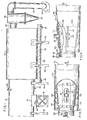
- the dehydrating apparatus illustrated includes an engine room 10 in which is contained the pulse jet engine to be described hereinafter.
- the engine room is supported in elevated position above a floor by means of a plurality of legs 12 (Fig. 2).
- An air inlet conduit 14 extends through the bottom wall of the engine room and is provided on its outer side with a peripheral flange 16 by which to mount an air inlet fan 18.
- the fan is arranged to inject atmospheric air into the engine room, whereby to supply oxygen for combustion in the pulse jet engine.
- a combustible fuel inlet 20 extends through the bottom wall of the engine room for supplying fuel to the pulse jet engine.
- a wet product inlet conduit 22 extends through the top wall of the engine room for delivering wet products to be dehydrated.
- the engine room preferably is constructed of double walls with the space therebetween filled with sand or other sound deadening and vibration damping material.
- the front end of the engine room is joined to the rear end of a collector room 24 which also is supported above ground by means of legs 26.
- the collector room is preferably circular in cross section to facilitate the gravitation of the dried solid material to a central longitudinal opening which extends the full length of the collector room.
- This opening communicates with an elongated screw conveyor housing 28 containing an elongated conveyor screw 30.
- the rearward end of the screw is connected to a drive motor and gear reducer unit 32 for rotating the screw at a selected speed.
- the forward end of the screw conveyor housing communicates with a dried product outlet pipe 34.
- This pipe may communicate with bagging equipment by which the dried product is containerized. Alternatively, the outlet pipe may discharge the dried product onto a conveyor for transport to further processing equipment.
- the front wall of the collector room is provided with an opening adjacent the upper end thereof for communication through an exhaust gas outlet pipe 36 with the inlet of a cyclone or other form of separator 38.
- the separator functions by centrifugal or other action to separate the solid fines material from the gases, the fines material gravitating downward to the outlet 40 of the separator where they are collected.
- the gases are drawn from the upper end of the separator through a gas outlet pipe 42 which communicates with the inlet of a gas outlet fan 44. The clean gases thus are exhausted to the atmosphere at the outlet of the fan.
- the engine room is shown to contain a pulse jet engine.
- the engine is mounted on a platform 46 supported on a framework 48 which extends the length of the engine room a spaced distance above the bottom wall thereof.
- the rearward end of the platform terminates short of the rear wall of the engine room to provide an opening for the passage of air upwardly from the air inlet fan.
- the pulse jet engine is mounted resiliently above the support platform, to cushion the platform and engine room walls from vibrations incident to the operation of the engine.
- the resilient mountings are shown to comprise a front coil spring 50 and a rear pair of coil springs 52 extending upward from the platform and mounting plates 54 at their upper ends.
- Bolts 56 secured removably to the plates serve to secure thereto brackets 58 which connect to front and rear portions of the pulse jet engine.
- the pulse jet engine includes a combustion chamber section 60 provided with a spark plug 62 or other ignition means for igniting combustible fuel.
- This section includes an air inlet end portion 64 which receives atmospheric air from the engine room, and a combustion gas outlet portion 66.
- the combustion gas outlet portion communicates through an arcuate coupling section 68 with a tailpipe section 70 which, in turn, communicates at its exhaust outlet end with a materials dehydration section 72.
- the combustion chamber section is provided at its exhaust gas outlet end with a perpheri ⁇ l flange 74 arranged for removable connection to a corresponding flange 76 at the adjacnet end of the arcuate coupling section 68, as by means of a plurality of bolts 78.
- the opposite end of the coupling section is fitted with an outer, forwardly projecting annular collar 80 dimensioned to freely receive therein the adjacent end of the tailpipe section 70.
- the opposite end of the tailpipe section is, in similar manner, freely received within an enlarged collar 82 secured to and extending rearwardly of the rearward end of the dehydration section 72.
- the collars are interconnected by a turnbuckle assembly which includes an elongated threaded rod 84 received at its opposite ends in threaded nuts 86.
- Each nut is secured to a pair of laterally spaced lugs 88 which receive between them an ear 90 extending upwardly from the associated collar.
- Registering openings in the lugs and ears receive a pivot pin 92 for joining them together.
- the turnbuckle rod is rotated in the direction to move the collars apart sufficiently to release the tailpipe.
- the dehydration section 72 preferably is in the form of a truncated cone. It is supported in a saddle member 94 which is secured to and extends through a mounting plate 96.
- the mounting plate is secured removably to a forward transverse wall 10' of the engine room, as by bolts 98. Said wall also is provided with an opening for passage of the saddle member.
- the dehydration cone is mounted in the saddle by inserting it through the forward end of the saddle and coupling it to the tailpipe.
- the cone is supported in the saddle primarily at the forward end thereof, thereby allowing for movement of the pulse jet engine on its resilient mountings during operation.
- the wet product inlet conduit 22 is connected to the dehydration cone 72 for introduction of the wet product into the cone in a direction substantially perpendicular to the direction of movement of the high velocity gases of combustion passing through the tailpipe and exiting the forward end of the dehydration cone.
- the point of introduction of the wet product into the dehydration section 72 be selected to maximize the dehydration process. This is accomplished empirically by moving the point of introduction along the length of the dehydration section, for each type and moisture content of material to be dried, until there is achieved substantially complete and instantaneous dehydration of the product before it exits the forward end of the dehydration section.
- Means preferably is provided to facilitate the adjustment of the position of the wet product inlet conduit 22 along the length of the dehydration section.
- the inner, unjection nozzle end of the wet product inlet conduit 22 is connected to an elongated nozzle plate 100 which overlies and covers a longitudinally elongated opening 102 in the dehydration cone.
- the plate is curved transversely to approximate the progressively changing diameter of the dehydration cone, to allow longitudinal adjustment of the position of the injection nozzle along the length of the elongated slot in the cone, while providing an adequate seal between the plate and cone.
- the plate 100 and hence the position of the injection nozzle end of conduit 22, is secured in any desired position of adjustment by means of a pair of outer clamp bands 104 and 106 which encircle the dehydration cone and are secured together releasably by bolts 108 extended through aligned openings in the side flanges 110 of the clamp plates.
- the upper clamp band 104 is provided with a longitudinally elongated opening 112 for the reception of the injection nozzle end of conduit 22. Accordingly, the injection nozzle may be adjusted along the length of the dehydration cone by loosening the clamp bolts sufficiently to relieve the clamping pressure of the upper clamp band on the injection nozzle plate 100 to allow the latter to be moved longitudinally along the cone. The desired position of adjustment of the nozzle then is secured by tightening the clamp bolts, as will be understood.
- Combustible fuel such as oil, gas, etc. is delivered to the combustion chamber 60 by one or more infeed lines, such as the two lines 114 illustrated, connected to the fuel inlet conduit 20.
- An additional fuel inlet line 116 may be utilized to deliver combustible fuel to the downstream end of the arcuate coupler 68, to supply additional heat to the inlet end of the tailpipe, to increase the capacity of the system and to accommodate all types of fuels. This feature offers the same advantages for other uses of all types of pulse jet engines.
- the plate 96 supporting the dehydration cone saddle 94 also supports an augmenter is positioned in axial alignment with the air inlet portion 64 of the combustion chamber and extends through the forward engine room wall 10'. It functions to communicate the high velocity combustion gases emitted as back pressure from the combustion chamber, into the collector room 24. These gases assist in the creation of gas flow in the downstream direction through the collector room and separator 38 to the gas outlet fan.
- the pulse jet engine is activated by delivery of combustible fuel to the combustion chamber where it is ignited by spark from the plug 62.
- a slurry, paste or particulate form of wet product is fed, generally under pressure, through the inlet conduit 22 from whence it enters the dehydration cone 72 in a direction substantially perpendicular to the direction of flow of high velocity combustion gases through the cone.
- the position of the injection nozzle is established at which the material emerging from the dehydration cone is substantially completely dried. Considering the short distance from the injection nozzle to the outfeed end of the dehydration cone as being no more than about 30 to 45 centimeters, it is apparent that dehydration of the wet product occurs substantially instantaneously as it enters the cone from the injection nozzle.
- the fine particles carried with the high velocity combustion gases are drawn into the separator 38 which, by virtue of its characteristic operation, functions to separate the fine solids from the gas.
- the gas outlet.fan 44 expels the clean gases of combustion into the atmosphere, or delivers them to other apparatus for further processing or use.
- the apparatus described hereinbefore may be utilized to effect the dehydration of a wide variety of types of materials. For example, it may be used to dehydrate chicken, rabbit, goat and other animal manures for packaging and sale as dried products. It may be used to remove contaminants from industrial sludges, such as detergent from wash waters before discharging the water to a river. It may also be utilized to recover valuable materials, such as gold or other metals otherwise lost in the course of industrial processing.
- an inlet 120 may be provided at any desired location downstream from the combustion chamber 60 for the introduction of previously dried particulate material which is desired to be calcined, or roasted to burn off undesirable components.
- the location of the inlet 120 will be governed by the degree of resistance of the material to calcining. For example, an easily calcined material may be introduced at the location of inlet 22, whereas a highly resistant material may require introduction at the location of inlet 120 in order to have longer residence time in the hot gases of combustion of the engine.
Landscapes
- Engineering & Computer Science (AREA)
- Chemical & Material Sciences (AREA)
- Mechanical Engineering (AREA)
- General Engineering & Computer Science (AREA)
- Combustion & Propulsion (AREA)
- Chemical Kinetics & Catalysis (AREA)
- Life Sciences & Earth Sciences (AREA)
- Sustainable Development (AREA)
- Drying Of Solid Materials (AREA)
Applications Claiming Priority (2)
| Application Number | Priority Date | Filing Date | Title |
|---|---|---|---|
| US48162883A | 1983-04-04 | 1983-04-04 | |
| US481628 | 1995-06-07 |
Publications (3)
| Publication Number | Publication Date |
|---|---|
| EP0122665A2 true EP0122665A2 (fr) | 1984-10-24 |
| EP0122665A3 EP0122665A3 (en) | 1985-04-10 |
| EP0122665B1 EP0122665B1 (fr) | 1988-09-14 |
Family
ID=23912730
Family Applications (1)
| Application Number | Title | Priority Date | Filing Date |
|---|---|---|---|
| EP19840200483 Expired EP0122665B1 (fr) | 1983-04-04 | 1984-04-03 | Appareil de déshydratation |
Country Status (2)
| Country | Link |
|---|---|
| EP (1) | EP0122665B1 (fr) |
| DE (1) | DE3474060D1 (fr) |
Cited By (9)
| Publication number | Priority date | Publication date | Assignee | Title |
|---|---|---|---|---|
| EP0219235A3 (fr) * | 1985-10-03 | 1987-07-29 | Sonodyne Industries, Inc. | Dessicateur pour matières granuleuses avec combustion pulsative |
| EP0234092A1 (fr) * | 1985-10-03 | 1987-09-02 | Sonodyne Industries, Inc. | Dessiccateur pour matières granuleuses avec combustion pulsative |
| EP0221999A4 (fr) * | 1985-05-09 | 1988-06-14 | Drytech Corp | Procede et appareil d'elimination d'elements volatiles contenus dans des produits liquides, ou de deshydratation de ces produits. |
| FR2620864A1 (fr) * | 1987-09-18 | 1989-03-24 | Rhone Poulenc Chimie | Materiaux supraconducteurs et leur procede de preparation |
| US5071827A (en) * | 1987-09-18 | 1991-12-10 | Rhone-Poulenc Chimie | Production of superconductor materials |
| EP0265490B1 (fr) * | 1986-04-16 | 1995-10-18 | NEA Technology Transfer Corporation | Systeme d'energie de combustion pulsee |
| EP0824088A4 (fr) * | 1996-02-29 | 2000-05-03 | Osaka Fuji Kogyo Kk | Procede de traitement de dechets humains sans drainage par sechage et combustion pulsatoire |
| CN113310286A (zh) * | 2021-06-04 | 2021-08-27 | 黑龙江中医药大学附属第一医院(黑龙江中医药大学第一临床医学院) | 一种治疗银屑病中药加工用烘干装置 |
| CN117387335A (zh) * | 2023-11-30 | 2024-01-12 | 南京龙德生物科技有限公司 | 一种同种异体骨植入材料生产用甩动式干燥装置 |
Families Citing this family (1)
| Publication number | Priority date | Publication date | Assignee | Title |
|---|---|---|---|---|
| CN104880046B (zh) * | 2014-12-30 | 2019-11-22 | 浙江芸洁科技有限公司 | 黏性物料干燥设备及其用于无so2魔芋粉的生产方法 |
Family Cites Families (3)
| Publication number | Priority date | Publication date | Assignee | Title |
|---|---|---|---|---|
| US3508339A (en) * | 1965-11-30 | 1970-04-28 | Gen Electric | Drying apparatus and process |
| US3618655A (en) * | 1969-08-05 | 1971-11-09 | Marine Technology Inc | Spray drying apparatus |
| US4171243A (en) * | 1975-06-17 | 1979-10-16 | The Chemithon Corporation | Spray drying method |
-
1984
- 1984-04-03 EP EP19840200483 patent/EP0122665B1/fr not_active Expired
- 1984-04-03 DE DE8484200483T patent/DE3474060D1/de not_active Expired
Cited By (12)
| Publication number | Priority date | Publication date | Assignee | Title |
|---|---|---|---|---|
| EP0221999A4 (fr) * | 1985-05-09 | 1988-06-14 | Drytech Corp | Procede et appareil d'elimination d'elements volatiles contenus dans des produits liquides, ou de deshydratation de ces produits. |
| EP0219235A3 (fr) * | 1985-10-03 | 1987-07-29 | Sonodyne Industries, Inc. | Dessicateur pour matières granuleuses avec combustion pulsative |
| EP0234092A1 (fr) * | 1985-10-03 | 1987-09-02 | Sonodyne Industries, Inc. | Dessiccateur pour matières granuleuses avec combustion pulsative |
| EP0265490B1 (fr) * | 1986-04-16 | 1995-10-18 | NEA Technology Transfer Corporation | Systeme d'energie de combustion pulsee |
| FR2620864A1 (fr) * | 1987-09-18 | 1989-03-24 | Rhone Poulenc Chimie | Materiaux supraconducteurs et leur procede de preparation |
| EP0309322A1 (fr) * | 1987-09-18 | 1989-03-29 | Rhone-Poulenc Chimie | Matériaux supraconducteurs et leur procédé de préparation |
| US5071827A (en) * | 1987-09-18 | 1991-12-10 | Rhone-Poulenc Chimie | Production of superconductor materials |
| US5118659A (en) * | 1987-09-18 | 1992-06-02 | Rhone-Poulenc Chimie | Production of superconductor materials using a helicoidal flow of hot gases to effect pulverization and drying |
| EP0824088A4 (fr) * | 1996-02-29 | 2000-05-03 | Osaka Fuji Kogyo Kk | Procede de traitement de dechets humains sans drainage par sechage et combustion pulsatoire |
| CN113310286A (zh) * | 2021-06-04 | 2021-08-27 | 黑龙江中医药大学附属第一医院(黑龙江中医药大学第一临床医学院) | 一种治疗银屑病中药加工用烘干装置 |
| CN113310286B (zh) * | 2021-06-04 | 2022-06-14 | 黑龙江中医药大学附属第一医院(黑龙江中医药大学第一临床医学院) | 一种治疗银屑病中药加工用烘干装置 |
| CN117387335A (zh) * | 2023-11-30 | 2024-01-12 | 南京龙德生物科技有限公司 | 一种同种异体骨植入材料生产用甩动式干燥装置 |
Also Published As
| Publication number | Publication date |
|---|---|
| EP0122665A3 (en) | 1985-04-10 |
| EP0122665B1 (fr) | 1988-09-14 |
| DE3474060D1 (en) | 1988-10-20 |
Similar Documents
| Publication | Publication Date | Title |
|---|---|---|
| US5199354A (en) | Mobile soil remediation system | |
| EP0122665A2 (fr) | Appareil de déshydratation | |
| EP3064877B1 (fr) | Système pour éliminer l'humidité du charbon | |
| US4226668A (en) | Spray drying apparatus utilizing pulse jet engines | |
| CA2187074A1 (fr) | Appareil de reactivation du carbone | |
| US4936231A (en) | Solid waste garbage incinerator system | |
| US4637794A (en) | Pulse combustion drying apparatus for particulate materials | |
| US4624635A (en) | Construction for pulse jet combustor dehydration section | |
| US4832598A (en) | Pulse combustion apparatus | |
| EP0554001B1 (fr) | Système et procédé pour amener du matériau pâteux ou de la boue à un four | |
| US4412814A (en) | Apparatus and method for operating a brick kiln | |
| CN215312166U (zh) | 一种喷雾造粒机 | |
| EP0234092A1 (fr) | Dessiccateur pour matières granuleuses avec combustion pulsative | |
| EP0565478B1 (fr) | Sécheur tubulaire rotatif | |
| US4695249A (en) | Feed system for particle drying pulse jet combustors | |
| SU1386826A2 (ru) | Устройство дл сушки дисперсных материалов | |
| US4455968A (en) | Boilers | |
| RU2038872C1 (ru) | Аэродинамическая установка для обогащения сыпучих материалов | |
| RU93028665A (ru) | Установка для обработки органических отходов | |
| SU1222310A1 (ru) | Установка сухого обогащени заполнителей дл бетонных смесей | |
| SU646167A1 (ru) | Труба-сушилка | |
| SU1064077A1 (ru) | Устройство дл подготовки коры и древесных отходов к пофракционному сжиганию в котлоагрегате | |
| RU2303756C1 (ru) | Сушилка с движущимися емкостями | |
| JP2024033961A (ja) | 分離装置 | |
| SU1041836A1 (ru) | Распылительна сушилка |
Legal Events
| Date | Code | Title | Description |
|---|---|---|---|
| PUAI | Public reference made under article 153(3) epc to a published international application that has entered the european phase |
Free format text: ORIGINAL CODE: 0009012 |
|
| AK | Designated contracting states |
Designated state(s): BE DE FR GB NL |
|
| PUAL | Search report despatched |
Free format text: ORIGINAL CODE: 0009013 |
|
| AK | Designated contracting states |
Designated state(s): BE DE FR GB NL |
|
| 17P | Request for examination filed |
Effective date: 19851010 |
|
| 17Q | First examination report despatched |
Effective date: 19860708 |
|
| D17Q | First examination report despatched (deleted) | ||
| GRAA | (expected) grant |
Free format text: ORIGINAL CODE: 0009210 |
|
| AK | Designated contracting states |
Kind code of ref document: B1 Designated state(s): BE DE FR GB NL |
|
| REF | Corresponds to: |
Ref document number: 3474060 Country of ref document: DE Date of ref document: 19881020 |
|
| ET | Fr: translation filed | ||
| PGFP | Annual fee paid to national office [announced via postgrant information from national office to epo] |
Ref country code: FR Payment date: 19890424 Year of fee payment: 6 |
|
| PGFP | Annual fee paid to national office [announced via postgrant information from national office to epo] |
Ref country code: BE Payment date: 19890428 Year of fee payment: 6 |
|
| PGFP | Annual fee paid to national office [announced via postgrant information from national office to epo] |
Ref country code: NL Payment date: 19890430 Year of fee payment: 6 Ref country code: GB Payment date: 19890430 Year of fee payment: 6 |
|
| PGFP | Annual fee paid to national office [announced via postgrant information from national office to epo] |
Ref country code: DE Payment date: 19890502 Year of fee payment: 6 |
|
| PLBE | No opposition filed within time limit |
Free format text: ORIGINAL CODE: 0009261 |
|
| STAA | Information on the status of an ep patent application or granted ep patent |
Free format text: STATUS: NO OPPOSITION FILED WITHIN TIME LIMIT |
|
| 26N | No opposition filed | ||
| PG25 | Lapsed in a contracting state [announced via postgrant information from national office to epo] |
Ref country code: GB Effective date: 19900403 |
|
| PG25 | Lapsed in a contracting state [announced via postgrant information from national office to epo] |
Ref country code: BE Effective date: 19900430 |
|
| BERE | Be: lapsed |
Owner name: SONODYNE INDUSTRIES INC. Effective date: 19900430 |
|
| PG25 | Lapsed in a contracting state [announced via postgrant information from national office to epo] |
Ref country code: NL Effective date: 19901101 |
|
| GBPC | Gb: european patent ceased through non-payment of renewal fee | ||
| NLV4 | Nl: lapsed or anulled due to non-payment of the annual fee | ||
| PG25 | Lapsed in a contracting state [announced via postgrant information from national office to epo] |
Ref country code: FR Effective date: 19901228 |
|
| PG25 | Lapsed in a contracting state [announced via postgrant information from national office to epo] |
Ref country code: DE Effective date: 19910101 |
|
| REG | Reference to a national code |
Ref country code: FR Ref legal event code: ST |