EP0122708B1 - Obturateur anti-éruption annulaire - Google Patents
Obturateur anti-éruption annulaire Download PDFInfo
- Publication number
- EP0122708B1 EP0122708B1 EP84301549A EP84301549A EP0122708B1 EP 0122708 B1 EP0122708 B1 EP 0122708B1 EP 84301549 A EP84301549 A EP 84301549A EP 84301549 A EP84301549 A EP 84301549A EP 0122708 B1 EP0122708 B1 EP 0122708B1
- Authority
- EP
- European Patent Office
- Prior art keywords
- packer
- annular
- opening
- blowout preventer
- plug
- Prior art date
- Legal status (The legal status is an assumption and is not a legal conclusion. Google has not performed a legal analysis and makes no representation as to the accuracy of the status listed.)
- Expired
Links
Images



Classifications
-
- E—FIXED CONSTRUCTIONS
- E21—EARTH OR ROCK DRILLING; MINING
- E21B—EARTH OR ROCK DRILLING; OBTAINING OIL, GAS, WATER, SOLUBLE OR MELTABLE MATERIALS OR A SLURRY OF MINERALS FROM WELLS
- E21B33/00—Sealing or packing boreholes or wells
- E21B33/02—Surface sealing or packing
- E21B33/03—Well heads; Setting-up thereof
- E21B33/06—Blow-out preventers, i.e. apparatus closing around a drill pipe, e.g. annular blow-out preventers
Definitions
- This invention relates to annular blowout preventers.
- the resilient packer of an annular blowout preventer can wear and be damaged.
- Changing the packer in present annular blowout preventers requires the removal of the upper end connection plus other elements of the BOP stack which are above the annular preventer such as the bell nipple, stripper, or rotating head. To do this clearance must be provided between the rig floor substructure and the top of the BOP to allow the top to be lifted clear to provide access to the packer. This is very inconvenient in snubbing operations. Also the top portion of most present annular blowout preventers is large and heavy which reduces the clearance and increases the difficulty of replacing the packer.
- U.S. Patent No. 2154955 discloses a well casing control valve having removable side plates allowing access for ram changes.
- U.S. Patent No. 2320974 discloses a ram type blowout preventer with removable side plates for changing internal ram operating mechanisms and rams.
- U.S. Patent No. 2592197 discloses a ram type blowout preventer with side windows for each ram for insertion and removal of the rams with covers secured over the windows for each ram for insertion and removal of the rams with covers secured over the windows.
- an annular blowout preventer comprising a body having a central bore extending therethrough with an annular packer recess surrounding and opening to said bore, an annular packer positioned in said recess in surrounding relationship to said bore, means for loading said packer to seal within said bore, characterised in that the preventer includes an opening through the side of said body into said packer recess, a plug for sealing said opening, and means for retaining said plug in said opening, said plug having an interior surface for supporting the exterior surface of said packer in said opening.
- a feature of the present invention is the provision of an improved annular blowout preventer in which the annular packer may be changed without regard to the vertical clearance available.
- Annular blowout preventer 10 includes body 12 having central bore 14 extending therethrough with packer recess 16 surrounding and opening onto bore 14.
- Body 12 includes lower flange 18, inner upstanding rim 20 and outer upstanding rim 22.
- Upper end closure 24 is threaded into rim 22 and has depending rim 26 extending to a position between rims 20 and 22, and forming annular chamber 28.
- Upper end closure 24 extends inward as flange 30 to proved shoulder 32 at the upper end of packer recess 16.
- Annular packer 34 is positioned in packer recess 16 between shoulder 32 and annular actuating plate 36.
- Means for axially loading annular packer 34 is provided by piston 38 which is slidable in chamber 28 responsive to pressure through port 38a and port 38b and connected to annular actuating plate 36 by annular arm 40.
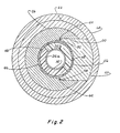
- Annular packer 34 includes resilient annulus 41 with upper insert plates 42 and lower insert plates 44 embedded therein. Annular packer 34 is split and preferably has two semi-annular sections 34a and 34b. as shown in FIGURE 2. Ring 46 is embedded in the exterior of resilient annulus 41 and has a plurality of tapped holes 48 to allow firm engagement of packer 34 during removal. Annular packer 34 is split as described and shown to allow it to be removed easily from recess 16 through opening 50 in rim 22 and depending rim 26 of end closure 24 as best seen in FIGURE 2.
- Opening 50 includes inner rectangular opening 52 with shoulder 54 at its inner end and outer rectangular opening 56 with shoulder 58 facing outward at the inner end of opening 56.
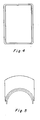
- Plug 60 is shaped to fit closely into opening 52 and 56, to engage shoulder 54 and capture seal ring 62 between shoulder 64 on plug 60 and shoulder 58.
- the inner surface 66 of plug 60 is cylindrical to form a portion of the wall of recess 16.
- Plug 60 is retained in opening 50 by sleeve 68 which surrounds outer rim 22 of body 12 from a position above opening 50 to a position below opening 50.
- Suitable means for supporting sleeve 68 in its plug retaining position is provided in the form of lugs 70 secured to outer rim 22 by screws 72.
- packer 34 Whenever it is desired to replace packer 34 then screws 72 are removed and sleeve 68 is lowered to the position shown in FIGURE 3 so that plug 60 can be removed. With plug 60 removed packer sections 34a and 34b can be removed even with a pipe extending through bore 14.
- annular blowout preventer 80 includes outer rim 82 and depending rim 84 of end closure with inner rectangular opening 86 extending transversely thereof and outer rectangular openings 88 and 90 provide shoulders 92 and 94.
- Plugs 96 and 98 are positioned therein and seal rings 100 and 102 are positioned between shoulders 104 and 106 on plugs 96 and 98 and shoulders 92 and 94.
- Sleeve 108 surrounds rim 82 and retains plugs 96 and 98 in position sealing both ends of bore 86.
- Packer 110 includes sections 112 and 114 and has ring 116 embedded therein with tapped holes 118 to assist in removal of packer sections 112 and 114 through opposite sides of bore 86 after plugs 96 and 98 are removed.
Landscapes
- Geology (AREA)
- Life Sciences & Earth Sciences (AREA)
- Engineering & Computer Science (AREA)
- Mining & Mineral Resources (AREA)
- Geochemistry & Mineralogy (AREA)
- Fluid Mechanics (AREA)
- Environmental & Geological Engineering (AREA)
- General Life Sciences & Earth Sciences (AREA)
- Physics & Mathematics (AREA)
- Acyclic And Carbocyclic Compounds In Medicinal Compositions (AREA)
- Consolidation Of Soil By Introduction Of Solidifying Substances Into Soil (AREA)
- Pressure Vessels And Lids Thereof (AREA)
- Self-Closing Valves And Venting Or Aerating Valves (AREA)
- Closures For Containers (AREA)
- Blow-Moulding Or Thermoforming Of Plastics Or The Like (AREA)
- Processing Of Meat And Fish (AREA)
Claims (10)
Priority Applications (1)
| Application Number | Priority Date | Filing Date | Title |
|---|---|---|---|
| AT84301549T ATE36578T1 (de) | 1983-04-13 | 1984-03-08 | Ringfoermiges ausblasventil. |
Applications Claiming Priority (2)
| Application Number | Priority Date | Filing Date | Title |
|---|---|---|---|
| US48451283A | 1983-04-13 | 1983-04-13 | |
| US484512 | 1983-04-13 |
Publications (3)
| Publication Number | Publication Date |
|---|---|
| EP0122708A2 EP0122708A2 (fr) | 1984-10-24 |
| EP0122708A3 EP0122708A3 (en) | 1985-05-15 |
| EP0122708B1 true EP0122708B1 (fr) | 1988-08-17 |
Family
ID=23924456
Family Applications (1)
| Application Number | Title | Priority Date | Filing Date |
|---|---|---|---|
| EP84301549A Expired EP0122708B1 (fr) | 1983-04-13 | 1984-03-08 | Obturateur anti-éruption annulaire |
Country Status (5)
| Country | Link |
|---|---|
| EP (1) | EP0122708B1 (fr) |
| JP (1) | JPS59199989A (fr) |
| AT (1) | ATE36578T1 (fr) |
| DE (1) | DE3473489D1 (fr) |
| SG (1) | SG19789G (fr) |
Families Citing this family (2)
| Publication number | Priority date | Publication date | Assignee | Title |
|---|---|---|---|---|
| US6352120B1 (en) * | 1999-02-08 | 2002-03-05 | Hydril Company | Packer insert for sealing on multiple items in the wellbore |
| US9938793B2 (en) | 2015-11-24 | 2018-04-10 | Freudenberg Oil & Gas, Llc | Spherical blow out preventer annular seal |
Family Cites Families (5)
| Publication number | Priority date | Publication date | Assignee | Title |
|---|---|---|---|---|
| US2154955A (en) * | 1937-02-02 | 1939-04-18 | Kerotest Mfg Company | Well casing control valve |
| US2320974A (en) * | 1941-08-18 | 1943-06-01 | Macclatchie Mfg Company Of Cal | Blowout preventer |
| US2592197A (en) * | 1947-10-27 | 1952-04-08 | Jr Frank J Schweitzer | Side-plug hydraulic cellar gate |
| US3915425A (en) * | 1973-01-22 | 1975-10-28 | Hydril Co | Blowout preventer with variable inside diameter |
| US4310139A (en) * | 1980-04-04 | 1982-01-12 | Cameron Iron Works, Inc. | Annular blowout preventer |
-
1984
- 1984-03-08 AT AT84301549T patent/ATE36578T1/de active
- 1984-03-08 DE DE8484301549T patent/DE3473489D1/de not_active Expired
- 1984-03-08 EP EP84301549A patent/EP0122708B1/fr not_active Expired
- 1984-04-10 JP JP59071675A patent/JPS59199989A/ja active Granted
-
1989
- 1989-03-31 SG SG197/89A patent/SG19789G/en unknown
Also Published As
| Publication number | Publication date |
|---|---|
| EP0122708A3 (en) | 1985-05-15 |
| EP0122708A2 (fr) | 1984-10-24 |
| ATE36578T1 (de) | 1988-09-15 |
| SG19789G (en) | 1989-09-01 |
| JPS59199989A (ja) | 1984-11-13 |
| JPH0361834B2 (fr) | 1991-09-24 |
| DE3473489D1 (en) | 1988-09-22 |
Similar Documents
| Publication | Publication Date | Title |
|---|---|---|
| US4579314A (en) | Annular blowout preventer | |
| US2731281A (en) | Kelly packer and blowout preventer | |
| US4448255A (en) | Rotary blowout preventer | |
| US3272222A (en) | Blowout preventer | |
| US2927774A (en) | Rotary seal | |
| US4099699A (en) | Annular blowout preventer | |
| US2754136A (en) | Pressure actuated seal between concentric pipes | |
| US2304991A (en) | Valve pot | |
| CA2403881C (fr) | Systeme de tube de production avec robinet-vanne | |
| AU1009388A (en) | Annular wellhead seal | |
| US4488703A (en) | Valve apparatus | |
| NO301387B1 (no) | Brönnhodeanordning | |
| EP0108895B1 (fr) | Obturateur antiéruption annulaire | |
| US4007904A (en) | Annular blowout preventer | |
| BR8801896A (pt) | Fecho hermetico anular para cabecas de poco | |
| US4283039A (en) | Annular blowout preventer with upper and lower spherical sealing surfaces | |
| US4602794A (en) | Annular blowout preventer with upper and lower spherical sealing surfaces and rigid translation element | |
| US4095805A (en) | Annular blowout preventer | |
| EP0122708B1 (fr) | Obturateur anti-éruption annulaire | |
| US2751235A (en) | Well head pipe suspension | |
| US3489439A (en) | Means for releasably latching members in a well installation | |
| US4460150A (en) | Annular blowout preventer | |
| JPS61266795A (ja) | ウエルヘツド封鎖組立体 | |
| US2499614A (en) | Valve cover | |
| US2337221A (en) | Wellhead |
Legal Events
| Date | Code | Title | Description |
|---|---|---|---|
| PUAI | Public reference made under article 153(3) epc to a published international application that has entered the european phase |
Free format text: ORIGINAL CODE: 0009012 |
|
| AK | Designated contracting states |
Designated state(s): AT BE CH DE FR GB IT LI LU NL SE |
|
| PUAL | Search report despatched |
Free format text: ORIGINAL CODE: 0009013 |
|
| AK | Designated contracting states |
Designated state(s): AT BE CH DE FR GB IT LI LU NL SE |
|
| 17P | Request for examination filed |
Effective date: 19850916 |
|
| 17Q | First examination report despatched |
Effective date: 19860820 |
|
| D17Q | First examination report despatched (deleted) | ||
| GRAA | (expected) grant |
Free format text: ORIGINAL CODE: 0009210 |
|
| AK | Designated contracting states |
Kind code of ref document: B1 Designated state(s): AT BE CH DE FR GB IT LI LU NL SE |
|
| PG25 | Lapsed in a contracting state [announced via postgrant information from national office to epo] |
Ref country code: SE Effective date: 19880817 Ref country code: LI Effective date: 19880817 Ref country code: IT Free format text: LAPSE BECAUSE OF FAILURE TO SUBMIT A TRANSLATION OF THE DESCRIPTION OR TO PAY THE FEE WITHIN THE PRESCRIBED TIME-LIMIT;WARNING: LAPSES OF ITALIAN PATENTS WITH EFFECTIVE DATE BEFORE 2007 MAY HAVE OCCURRED AT ANY TIME BEFORE 2007. THE CORRECT EFFECTIVE DATE MAY BE DIFFERENT FROM THE ONE RECORDED. Effective date: 19880817 Ref country code: CH Effective date: 19880817 Ref country code: BE Effective date: 19880817 |
|
| REF | Corresponds to: |
Ref document number: 36578 Country of ref document: AT Date of ref document: 19880915 Kind code of ref document: T |
|
| REF | Corresponds to: |
Ref document number: 3473489 Country of ref document: DE Date of ref document: 19880922 |
|
| ET | Fr: translation filed | ||
| REG | Reference to a national code |
Ref country code: CH Ref legal event code: PL |
|
| PG25 | Lapsed in a contracting state [announced via postgrant information from national office to epo] |
Ref country code: LU Free format text: LAPSE BECAUSE OF NON-PAYMENT OF DUE FEES Effective date: 19890331 |
|
| PLBE | No opposition filed within time limit |
Free format text: ORIGINAL CODE: 0009261 |
|
| STAA | Information on the status of an ep patent application or granted ep patent |
Free format text: STATUS: NO OPPOSITION FILED WITHIN TIME LIMIT |
|
| 26N | No opposition filed | ||
| PGFP | Annual fee paid to national office [announced via postgrant information from national office to epo] |
Ref country code: GB Payment date: 19910222 Year of fee payment: 8 |
|
| PGFP | Annual fee paid to national office [announced via postgrant information from national office to epo] |
Ref country code: AT Payment date: 19910313 Year of fee payment: 8 |
|
| PGFP | Annual fee paid to national office [announced via postgrant information from national office to epo] |
Ref country code: FR Payment date: 19910320 Year of fee payment: 8 |
|
| PGFP | Annual fee paid to national office [announced via postgrant information from national office to epo] |
Ref country code: NL Payment date: 19910331 Year of fee payment: 8 |
|
| PGFP | Annual fee paid to national office [announced via postgrant information from national office to epo] |
Ref country code: DE Payment date: 19910402 Year of fee payment: 8 |
|
| REG | Reference to a national code |
Ref country code: GB Ref legal event code: 732 |
|
| PG25 | Lapsed in a contracting state [announced via postgrant information from national office to epo] |
Ref country code: GB Effective date: 19920308 Ref country code: AT Effective date: 19920308 |
|
| PG25 | Lapsed in a contracting state [announced via postgrant information from national office to epo] |
Ref country code: NL Effective date: 19921001 |
|
| GBPC | Gb: european patent ceased through non-payment of renewal fee | ||
| NLV4 | Nl: lapsed or anulled due to non-payment of the annual fee | ||
| PG25 | Lapsed in a contracting state [announced via postgrant information from national office to epo] |
Ref country code: FR Effective date: 19921130 |
|
| PG25 | Lapsed in a contracting state [announced via postgrant information from national office to epo] |
Ref country code: DE Effective date: 19921201 |
|
| REG | Reference to a national code |
Ref country code: FR Ref legal event code: ST |