EP0122731A1 - Amortisseur pour train d'atterrissage d'hélicoptère et hélicoptère équipé avec - Google Patents
Amortisseur pour train d'atterrissage d'hélicoptère et hélicoptère équipé avec Download PDFInfo
- Publication number
- EP0122731A1 EP0122731A1 EP84301853A EP84301853A EP0122731A1 EP 0122731 A1 EP0122731 A1 EP 0122731A1 EP 84301853 A EP84301853 A EP 84301853A EP 84301853 A EP84301853 A EP 84301853A EP 0122731 A1 EP0122731 A1 EP 0122731A1
- Authority
- EP
- European Patent Office
- Prior art keywords
- damper
- extension
- piston
- helicopter
- fluid passageway
- Prior art date
- Legal status (The legal status is an assumption and is not a legal conclusion. Google has not performed a legal analysis and makes no representation as to the accuracy of the status listed.)
- Withdrawn
Links
- 239000000725 suspension Substances 0.000 title claims abstract description 28
- 239000012530 fluid Substances 0.000 claims abstract description 88
- 230000006835 compression Effects 0.000 claims abstract description 31
- 238000007906 compression Methods 0.000 claims abstract description 31
- 238000013016 damping Methods 0.000 description 4
- 230000004048 modification Effects 0.000 description 4
- 238000012986 modification Methods 0.000 description 4
- 238000009434 installation Methods 0.000 description 2
- 238000004891 communication Methods 0.000 description 1
- 238000010348 incorporation Methods 0.000 description 1
- 230000000750 progressive effect Effects 0.000 description 1
Images

Classifications
-
- B—PERFORMING OPERATIONS; TRANSPORTING
- B64—AIRCRAFT; AVIATION; COSMONAUTICS
- B64C—AEROPLANES; HELICOPTERS
- B64C25/00—Alighting gear
- B64C25/32—Alighting gear characterised by elements which contact the ground or similar surface
- B64C25/58—Arrangements or adaptations of shock-absorbers or springs
- B64C25/60—Oleo legs
-
- B—PERFORMING OPERATIONS; TRANSPORTING
- B64—AIRCRAFT; AVIATION; COSMONAUTICS
- B64C—AEROPLANES; HELICOPTERS
- B64C25/00—Alighting gear
- B64C25/32—Alighting gear characterised by elements which contact the ground or similar surface
- B64C2025/325—Alighting gear characterised by elements which contact the ground or similar surface specially adapted for helicopters
Definitions
- This invention relates to a suspension damper for a helicopter undercarriage and to a helicopter incorporating same.
- Suspension dampers which comprise a hollow piston axially slidable in a cylinder filled with hydraulic fluid and in which damping is achieved by metering the fluid through a compression fluid passageway through which the fluid is caused to flow by movement of the piston during compression of the damper.
- An extension fluid passageway provides for fluid flow during extension of the damper, and may include means for metering this flow to restrict recoil movement.
- the fluid passageways are typically constituted by a valve assembly including a plurality of graded orifices and associated valves automatically operable depending on the direction of fluid flow to ensure appropriate damping during the compression and extension strokes, respectively.
- dampers have become known in the art as oleo pneumatic dampers or, simply, oleos, and are widely used in helicopter undercarriages.
- the invention provides a suspension damper for a helicopter undercarriage, the damper comprising a hollow piston having a piston head axially slidable in a cylinder filled with hydraulic fluid, a compression fluid passageway in the piston head through which hydraulic fluid is metered during compression of the damper and an extension fluid passageway through which hydraulic fluid flows during extension of the damper, characterised by selectively operable valve means adapted to close the extension fluid passageway to prevent extension of the damper whilst permitting further compression thereof.
- the invention provides a suspension damper for a helicopter undercarriage comprising a hollow piston having a piston head axially slidable in a cylinder filled with hydraulic fluid and serving to sub-divide the interior of the cylinder into a first chamber at one side of the piston and a second chamber at the other side, a compression fluid passageway comprising a metering orifice and non-return valve adapted to permit fluid to flow from the first chamber to the second chamber during compression of the damper and to prevent fluid flow in the reverse direction, and an extension fluid passageway interconnecting the chambers and adapted to permit fluid flow from the second chamber to the first chamber during extension of the damper, characterised by selectively operable valve means adapted to close the extension fluid passageway to prevent extension of the damper whilst permitting further compression thereof.
- the extension fluid passageway is located in the wall of the cylinder.
- the extension fluid passageway is located in a housing in a reduced diameter portion of the piston above the piston head, said reduced diameter portion extending through the cylinder to protrude from an upper end thereof.
- the valve means may comprise a two-position axially slidable valve in the housing, spring-loaded to a position in which it permits fluid flow through the extension fluid passageway, and cable means attached to the valve and extended through the reduced diameter portion of the piston for connection to operating means located at the protruding end thereof.
- the operating means may comprise a manually operated lever or a pivoted lever operatively associated with a piston located in a chamber in a housing at the protruding end of the piston, and means for connecting a pressurised hydraulic supply selectively to opposite sides of the piston in the chamber.
- the invention provides a helicopter having an undercarriage comprising a plurality of ground engaging wheels attached to a fuselage by suspension dampers each comprising a hollow piston having a piston head axially slidable in a cylinder filled with hydraulic fluid, a compression fluid passageway in the piston head through which hydraulic fluid is metered during compression of the damper as the wheels contact a landing surface, and an extension fluid passageway through which hydraulic fluid flows during extension of the damper as the helicopter lifts from the landing surface, characterised by selectively operable valve means adapted to close the extension fluid passageway when the helicopter is at rest on an unstable platform to reduce instability of the helicopter by preventing extension of the damper whilst permitting further compression thereof.
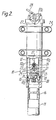
- a suspension damper generally indicated at 10 includes a hollow piston 11 axially slidable in a cylinder 12.
- a piston head 13 is formed at the upper end of the piston 11 and serves to sub-divide the interior of the cylinder 12 into a first chamber 12a above the piston head 13 and a second annular chamber 12b below the piston head 13.
- the chambers 12a and 12b are filled with hydraulic fluid through a charging valve 14, and apertures 15 through the wall of the hollow piston 11 provide fluid communication between the interior of the piston 11 and the annular chamber 12b.
- a compression fluid passageway consisting of a metering orifice 19 is provided in the piston head 13 and is associated with a non-return valve 20 adapted to permit a flow of hydraulic fluid from chamber 12a into the interior of the piston 11 and thence, through apertures 15 into chamber 12b, but to prevent flow in the reverse direction.
- a floating piston 16 is located inside the piston 11 for sliding movement along the length thereof.
- the portion of the piston 11 above the floating piston 16 is filled with hydraulic fluid as hereinbefore explained, and the portion below the floating piston 16 is filled with pressurised air through a charging valve 17.
- Piston 11 and cylinder 12 are interconnected by a mechanical scissors linkage 18, which during operation, prevents relative rotation of the parts.
- a suspension damper as so far described and provided with an arrangement to permit controlled fluid flow from the chamber 12b to the chamber 12a upon extension of the damper is known in the art and constitutes a device that is often referred to as an oleo pneumatic device or simply an oleo. Such oleos are widely used in helicopter undercarriages.
- the improvement that is the subject of the present invention consists of the provision of a selectively controllable extension fluid passageway 21 interconnecting chambers 12a and 12b to provide for the fluid flow during extension of the damper.
- the passageway 21 is formed in the wall of cylinder 12.
- a restrictor 22 is formed in the passageway 21, and a selectively operable valve 23 is rotatable between a position in which it permits hydraulic fluid to flow through the extension fluid passageway 21 into the chamber 12a and a position in which such a flow is prevented.
- Mounting brackets 24 are formed integral with the cylinder 12 to facilitate attachment of the suspension damper 10.
- the piston 11 includes a reduced diameter hollow portion 11a extended upwardly through the cylinder 12 to terminate at an upper end 11b protruding from the top of the cylinder 12.
- the chamber 12a in this embodiment is therefore annular in cross sectional-shape.
- a tube 25 is located through the portion lla above the piston head 13 and apertures 29 through the wall of the tube provide a fluid passageway between the chamber 12a and the metering orifice 19 and non-return valve 20 via a chamber 30.
- the extension fluid passageway 21 extends through the piston head 13 and a housing portion 26 at the lower end of portion lla which locates the selectively operable valve 23 that consists of a cylindrical valve located axially in the housing 26 across the extension passageway 21 and spring-loaded to the position illustrated in which a reduced diameter portion is aligned with the extension fluid passageway 21 to permit fluid flow.
- a restrictor 22 is located in the passageway 21.
- the passageway 21 communicates with the chamber 30 and thence via apertures 29 and tube 25 with chamber 12a.
- the valve 23 is connected by a cable 27 extending through the reduced diameter portion lla for connection at upper end llb to a pivotally mounted lever 28.
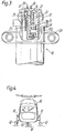
- Figure 3 illustrates a modification of Figure 2 in which the upper end of the operating cable 27 is attached to one arm of a lever 31 pivotally attached to a housing 32 supported internally at the upper end llb of piston 11.
- the other arm of lever 31 is pivotally attached to one end of a piston rod 33 attached to a piston 34 located in a chamber 35 in the housing 32.
- the portions of chamber 35 at opposite sides of the piston 34 are connected respectively by pipes 36 and 37 to connections 38 and 39 for selective connection to a supply of pressurised hydraulic fluid (not shown).
- Figure 4 illustrates a helicopter 40 having a tricycle undercarriage comprising a pair of nose wheels 41 and a main wheel 42 located at each side of the fuselage.
- the nose wheels 41 and each of the main wheels 42 are supported at the end of a suspension damper 10 attached to the fuselage 40 and constructed in accordance with any one of the embodiments hereinbefore described.
- each damper 10 In normal operation, eg. as the wheels 41 and 42 of the helicopter 40 contact a landing surface during landing, compression of each damper 10 occurs as required to cushion inpacts, causing upward movement of the piston 11 which forces hydraulic fluid from chamber 12a through the metering orifice 19 and non-return valve 20 to provide a damping force.
- the hydraulic fluid flows through the apertures 15 into the chamber 12b and also acts on the floating piston 16 to progressively compress the air below the piston 16 as the piston head 13 moves towards the end of its stroke in the cylinder 12, thereby to progressively increase the damping force.
- dampers constructed as shown in Figures 2 and 3 such upward movement of the piston 11 causes the upper end llb of the reduced diameter portion 11a to protrude from the upper end of cylinder 12.
- the restrictor 22 in the extension fluid passageway 21 is designed to provide a greater restriction to fluid flow than that provided by the metering orifice 19, and thereby effectively prevents flow through the passageway 21 during compression of the damper.
- a flow through the passageway 21 during the compression stroke can be prevented by the incorporation therein of a simple non-return valve.
- actuation of the valve 23 effectively blocks the return fluid flow through the extension fluid passageway 21 thereby preventing extension of the damper whilst permitting further compression which may be caused by movements of the unstable platform. Therefore, cyclical compression and extension of the damper is prevented whilst the helicopter is at rest on an unstable platform thereby effectively reducing or eliminating any consequent instability of the helicopter.
- valve 23 is actuated simply by manual rotation, and in the embodiment of Figure 2 by pivotal movement of the lever 28.
- the modification of Figure 3 introduces a remote control configuration in that actuation of the valve 23 to close passageway 21 is accomplished by applying hydraulic fluid through connection 38 and pipe 36 to move the piston 34 downwardly in chamber 35 thereby pivoting lever 31 attached to cable 27. Opening of the passageway 21 is of course accomplished by applying hydraulic pressure to connection 39, and it will be apparent that control of the hydraulic supplies to connectors 38, 39 could be at a remote location, for instance in the helicopter cabin.
Landscapes
- Engineering & Computer Science (AREA)
- Mechanical Engineering (AREA)
- Aviation & Aerospace Engineering (AREA)
- Fluid-Damping Devices (AREA)
Applications Claiming Priority (2)
| Application Number | Priority Date | Filing Date | Title |
|---|---|---|---|
| GB8309589 | 1983-04-08 | ||
| GB8309589 | 1983-04-08 |
Publications (1)
| Publication Number | Publication Date |
|---|---|
| EP0122731A1 true EP0122731A1 (fr) | 1984-10-24 |
Family
ID=10540826
Family Applications (1)
| Application Number | Title | Priority Date | Filing Date |
|---|---|---|---|
| EP84301853A Withdrawn EP0122731A1 (fr) | 1983-04-08 | 1984-03-19 | Amortisseur pour train d'atterrissage d'hélicoptère et hélicoptère équipé avec |
Country Status (1)
| Country | Link |
|---|---|
| EP (1) | EP0122731A1 (fr) |
Cited By (1)
| Publication number | Priority date | Publication date | Assignee | Title |
|---|---|---|---|---|
| FR2574349A1 (fr) * | 1984-12-12 | 1986-06-13 | Applic Mach Motrices | Element de suspension hydropneumatique d'un vehicule lourd ou du train d'atterrissage d'un aeronef |
Citations (3)
| Publication number | Priority date | Publication date | Assignee | Title |
|---|---|---|---|---|
| FR985519A (fr) * | 1949-02-21 | 1951-07-19 | Morane Saulnier | Perfectionnements aux amortisseurs de chocs à souplesse variable |
| GB768698A (en) * | 1954-05-05 | 1957-02-20 | British Messier Ltd | Improvements in or relating to shock absorbers for aircraft |
| GB1013821A (en) * | 1961-07-05 | 1965-12-22 | Dowty Rotol Ltd | Improvements relating to aircraft landing gear |
-
1984
- 1984-03-19 EP EP84301853A patent/EP0122731A1/fr not_active Withdrawn
Patent Citations (3)
| Publication number | Priority date | Publication date | Assignee | Title |
|---|---|---|---|---|
| FR985519A (fr) * | 1949-02-21 | 1951-07-19 | Morane Saulnier | Perfectionnements aux amortisseurs de chocs à souplesse variable |
| GB768698A (en) * | 1954-05-05 | 1957-02-20 | British Messier Ltd | Improvements in or relating to shock absorbers for aircraft |
| GB1013821A (en) * | 1961-07-05 | 1965-12-22 | Dowty Rotol Ltd | Improvements relating to aircraft landing gear |
Cited By (3)
| Publication number | Priority date | Publication date | Assignee | Title |
|---|---|---|---|---|
| FR2574349A1 (fr) * | 1984-12-12 | 1986-06-13 | Applic Mach Motrices | Element de suspension hydropneumatique d'un vehicule lourd ou du train d'atterrissage d'un aeronef |
| EP0186565A1 (fr) * | 1984-12-12 | 1986-07-02 | S.A.M.M.- Société d'Applications des Machines Motrices | Elément de suspension hydropneumatique d'un véhicule lourd ou du train d'atterrissage d'un aéronef |
| US4730817A (en) * | 1984-12-12 | 1988-03-15 | S.A.M.M. Societe D'applications Des Machines Motrices | Hydropneumatic suspension element of a heavy vehicle or a landing set of wheels of an aircraft |
Similar Documents
| Publication | Publication Date | Title |
|---|---|---|
| US5586781A (en) | Variable ride height vehicle suspension system | |
| US4381857A (en) | Programmed oleo-pneumatic shock absorber | |
| EP0228363B1 (fr) | Moyens de suspension pour une tuyère de pulvérisation | |
| US4588171A (en) | Shock absorber and air spring assembly | |
| US2905430A (en) | Control device for vehicle pneumatic suspension systems | |
| EP0160277B1 (fr) | Unité à amortisseur et ressort pneumatiques | |
| CN103209891B (zh) | 飞机起落架 | |
| US3300203A (en) | Hydropneumatic seat suspension | |
| US5944283A (en) | Crashworthy landing gear shock | |
| WO1998025819A1 (fr) | Amortisseur d'atterrisseur resistant a l'ecrasement | |
| US2377170A (en) | Fluid power mechanism | |
| EP0670231B1 (fr) | Ressort pneumatique | |
| EP0122731A1 (fr) | Amortisseur pour train d'atterrissage d'hélicoptère et hélicoptère équipé avec | |
| US4729538A (en) | Apparatus for hydraulically actuating a vehicle seat | |
| US2925970A (en) | Retractable aircraft landing element mounting | |
| US3653682A (en) | Energy absorbing device | |
| US3290037A (en) | Multiple orifice oleo-pneumatic shock/strut | |
| CA1265498A (fr) | Bequille telescopique deployable amortisseuse de chocs | |
| US3739519A (en) | Pressure operated retractable landing gear | |
| DE2406987B2 (de) | Stabilisierte Federung, insbesondere für Kraftfahrzeuge | |
| US1851623A (en) | Combined shock absorber and wheel brake for aircraft | |
| EP0082710B1 (fr) | Ensemble ressort et amortisseur pneumatique pour véhicules à cabine basculante | |
| GB2272267A (en) | Variable ride height vehicle suspension | |
| EP0336646A1 (fr) | Dispositif de suspension | |
| CA1282677C (fr) | Mecanisme hydraulique de commande d'un siege de vehicule |
Legal Events
| Date | Code | Title | Description |
|---|---|---|---|
| PUAI | Public reference made under article 153(3) epc to a published international application that has entered the european phase |
Free format text: ORIGINAL CODE: 0009012 |
|
| AK | Designated contracting states |
Designated state(s): DE FR GB IT |
|
| STAA | Information on the status of an ep patent application or granted ep patent |
Free format text: STATUS: THE APPLICATION IS DEEMED TO BE WITHDRAWN |
|
| 18D | Application deemed to be withdrawn |
Effective date: 19850705 |
|
| RIN1 | Information on inventor provided before grant (corrected) |
Inventor name: DEADY, MARTIN ALBERT |