EP0122828A1 - Verfahren und Vorrichtung zur Herstellung eines schraubenförmigen Produktes wie eine Feder aus Kunststoff - Google Patents
Verfahren und Vorrichtung zur Herstellung eines schraubenförmigen Produktes wie eine Feder aus Kunststoff Download PDFInfo
- Publication number
- EP0122828A1 EP0122828A1 EP84400493A EP84400493A EP0122828A1 EP 0122828 A1 EP0122828 A1 EP 0122828A1 EP 84400493 A EP84400493 A EP 84400493A EP 84400493 A EP84400493 A EP 84400493A EP 0122828 A1 EP0122828 A1 EP 0122828A1
- Authority
- EP
- European Patent Office
- Prior art keywords
- wire
- product
- helical
- torsion
- axis
- Prior art date
- Legal status (The legal status is an assumption and is not a legal conclusion. Google has not performed a legal analysis and makes no representation as to the accuracy of the status listed.)
- Granted
Links
- 239000004033 plastic Substances 0.000 title claims abstract description 23
- 229920003023 plastic Polymers 0.000 title claims abstract description 23
- 238000000034 method Methods 0.000 title claims description 37
- 238000004519 manufacturing process Methods 0.000 title claims description 8
- 239000000463 material Substances 0.000 title abstract description 15
- 229920002994 synthetic fiber Polymers 0.000 claims abstract description 7
- 238000004804 winding Methods 0.000 claims description 27
- 238000010438 heat treatment Methods 0.000 claims description 23
- 230000015572 biosynthetic process Effects 0.000 claims description 10
- 230000006835 compression Effects 0.000 claims description 6
- 238000007906 compression Methods 0.000 claims description 6
- 238000011144 upstream manufacturing Methods 0.000 claims description 4
- 239000005445 natural material Substances 0.000 claims description 3
- 238000007639 printing Methods 0.000 claims description 3
- 230000008569 process Effects 0.000 claims description 3
- 238000006073 displacement reaction Methods 0.000 claims description 2
- 239000002657 fibrous material Substances 0.000 claims 1
- 238000002955 isolation Methods 0.000 claims 1
- 230000014759 maintenance of location Effects 0.000 claims 1
- 230000009466 transformation Effects 0.000 abstract 1
- 239000000047 product Substances 0.000 description 101
- 238000010586 diagram Methods 0.000 description 10
- 239000000835 fiber Substances 0.000 description 9
- 230000006870 function Effects 0.000 description 7
- 238000001816 cooling Methods 0.000 description 5
- 230000000694 effects Effects 0.000 description 5
- 230000008901 benefit Effects 0.000 description 4
- 229920001971 elastomer Polymers 0.000 description 4
- 238000009499 grossing Methods 0.000 description 4
- 239000002184 metal Substances 0.000 description 4
- 239000000806 elastomer Substances 0.000 description 3
- 241000909536 Gobiesocidae Species 0.000 description 2
- 241001465754 Metazoa Species 0.000 description 2
- 239000013013 elastic material Substances 0.000 description 2
- 239000012467 final product Substances 0.000 description 2
- 230000003100 immobilizing effect Effects 0.000 description 2
- 238000009434 installation Methods 0.000 description 2
- 210000000056 organ Anatomy 0.000 description 2
- -1 polyethylene Polymers 0.000 description 2
- 238000007493 shaping process Methods 0.000 description 2
- 238000009941 weaving Methods 0.000 description 2
- 229910000497 Amalgam Inorganic materials 0.000 description 1
- 241001415961 Gaviidae Species 0.000 description 1
- 206010029216 Nervousness Diseases 0.000 description 1
- 239000004952 Polyamide Substances 0.000 description 1
- 239000004698 Polyethylene Substances 0.000 description 1
- 239000004743 Polypropylene Substances 0.000 description 1
- 238000004458 analytical method Methods 0.000 description 1
- 230000004323 axial length Effects 0.000 description 1
- 230000005540 biological transmission Effects 0.000 description 1
- 230000000903 blocking effect Effects 0.000 description 1
- 238000005253 cladding Methods 0.000 description 1
- 230000001427 coherent effect Effects 0.000 description 1
- 230000000295 complement effect Effects 0.000 description 1
- 239000002131 composite material Substances 0.000 description 1
- 238000010924 continuous production Methods 0.000 description 1
- 238000012937 correction Methods 0.000 description 1
- 230000008878 coupling Effects 0.000 description 1
- 238000010168 coupling process Methods 0.000 description 1
- 238000005859 coupling reaction Methods 0.000 description 1
- 238000005520 cutting process Methods 0.000 description 1
- 238000005516 engineering process Methods 0.000 description 1
- 238000000605 extraction Methods 0.000 description 1
- 230000008571 general function Effects 0.000 description 1
- 230000009477 glass transition Effects 0.000 description 1
- 238000005098 hot rolling Methods 0.000 description 1
- 238000002347 injection Methods 0.000 description 1
- 239000007924 injection Substances 0.000 description 1
- 238000003754 machining Methods 0.000 description 1
- 238000012423 maintenance Methods 0.000 description 1
- 230000007246 mechanism Effects 0.000 description 1
- 238000000465 moulding Methods 0.000 description 1
- 230000007935 neutral effect Effects 0.000 description 1
- 239000013307 optical fiber Substances 0.000 description 1
- 238000005457 optimization Methods 0.000 description 1
- 229920002647 polyamide Polymers 0.000 description 1
- 229920000728 polyester Polymers 0.000 description 1
- 229920000573 polyethylene Polymers 0.000 description 1
- 229920000642 polymer Polymers 0.000 description 1
- 229920001155 polypropylene Polymers 0.000 description 1
- 238000012545 processing Methods 0.000 description 1
- 230000002787 reinforcement Effects 0.000 description 1
- 239000011347 resin Substances 0.000 description 1
- 229920005989 resin Polymers 0.000 description 1
- 230000000717 retained effect Effects 0.000 description 1
- 238000005096 rolling process Methods 0.000 description 1
- 239000005060 rubber Substances 0.000 description 1
- 230000006641 stabilisation Effects 0.000 description 1
- 238000011105 stabilization Methods 0.000 description 1
- 238000003860 storage Methods 0.000 description 1
- 239000000126 substance Substances 0.000 description 1
- 238000006467 substitution reaction Methods 0.000 description 1
- 239000004753 textile Substances 0.000 description 1
- 229920001187 thermosetting polymer Polymers 0.000 description 1
- 210000002105 tongue Anatomy 0.000 description 1
- 238000012549 training Methods 0.000 description 1
- 230000007704 transition Effects 0.000 description 1
- 238000011282 treatment Methods 0.000 description 1
- 235000013311 vegetables Nutrition 0.000 description 1
- 229920002554 vinyl polymer Polymers 0.000 description 1
- 238000003466 welding Methods 0.000 description 1
Images

Classifications
-
- D—TEXTILES; PAPER
- D02—YARNS; MECHANICAL FINISHING OF YARNS OR ROPES; WARPING OR BEAMING
- D02G—CRIMPING OR CURLING FIBRES, FILAMENTS, THREADS, OR YARNS; YARNS OR THREADS
- D02G1/00—Producing crimped or curled fibres, filaments, yarns, or threads, giving them latent characteristics
-
- B—PERFORMING OPERATIONS; TRANSPORTING
- B29—WORKING OF PLASTICS; WORKING OF SUBSTANCES IN A PLASTIC STATE IN GENERAL
- B29C—SHAPING OR JOINING OF PLASTICS; SHAPING OF MATERIAL IN A PLASTIC STATE, NOT OTHERWISE PROVIDED FOR; AFTER-TREATMENT OF THE SHAPED PRODUCTS, e.g. REPAIRING
- B29C53/00—Shaping by bending, folding, twisting, straightening or flattening; Apparatus therefor
- B29C53/02—Bending or folding
- B29C53/12—Bending or folding helically, e.g. for making springs
-
- F—MECHANICAL ENGINEERING; LIGHTING; HEATING; WEAPONS; BLASTING
- F16—ENGINEERING ELEMENTS AND UNITS; GENERAL MEASURES FOR PRODUCING AND MAINTAINING EFFECTIVE FUNCTIONING OF MACHINES OR INSTALLATIONS; THERMAL INSULATION IN GENERAL
- F16F—SPRINGS; SHOCK-ABSORBERS; MEANS FOR DAMPING VIBRATION
- F16F1/00—Springs
- F16F1/36—Springs made of rubber or other material having high internal friction, e.g. thermoplastic elastomers
- F16F1/366—Springs made of rubber or other material having high internal friction, e.g. thermoplastic elastomers made of fibre-reinforced plastics, i.e. characterised by their special construction from such materials
- F16F1/3665—Wound springs
-
- B—PERFORMING OPERATIONS; TRANSPORTING
- B29—WORKING OF PLASTICS; WORKING OF SUBSTANCES IN A PLASTIC STATE IN GENERAL
- B29L—INDEXING SCHEME ASSOCIATED WITH SUBCLASS B29C, RELATING TO PARTICULAR ARTICLES
- B29L2031/00—Other particular articles
- B29L2031/774—Springs
- B29L2031/7742—Springs helical springs
Definitions
- the present invention relates to a non-metallic helical product having a longitudinal and radial elasticity of the spring type and the methods and devices for obtaining it.
- coil springs are metallic. Obtaining them results from a deformation by means of an appropriate tool, a metal wire. They constitute the main fraction of the longitudinally elastic elements, to which must be added the elastomeric products to one or more assembled threads, and the plastic products also in the form of a spring.
- plastic coil springs As regards the plastic coil springs, several manufacturing techniques are known. One of them consists in cutting a spring from the mass, by machining. A second consists in winding a plastic wire on a mandrel, subjecting it to a heat treatment to fix this deformation and removing the forming mandrel. A third is to form the spring by molding or injection. In addition to the often mediocre elasticity characteristics of these products, the main limit of these techniques lies in the short length of the products which they make it possible to obtain due to the technological constraints provided by the tooling. We have also thought of transposing the technology of manufacturing metal springs to elastic material by forcing the winding of a plastic wire on a pin associated with pressure and drive rollers so as to form a spring of great length. The springs thus obtained, despite the heat treatments which they undergo at the time of and after their manufacture, have mediocre elastic characteristics.
- non-metallic springs which consists in helically conforming a fiber reinforcement which is coated in the form of a thermosetting resin.
- the invention provides products which can be substituted for metal springs or elastic elastomer elements in many cases of use by offering by this substitution significant advantages, for example of oxidisability with respect to metallic products or longevity compared to rubbers, which allow optimization of the devices in which they operate.
- These products are helical elements produced from a base material which is neither metallic nor elastomeric, in the form of a wire of a plastically deformable natural or synthetic material consisting of a single filament or of the coherent group of several filaments or fibers.
- This material may be a plastic material or a natural material of plant or animal origin.
- the products of the invention find many other applications in the field of ropes, weaving, sheathing and lend themselves to numerous shaping and processing operations subsequent to their basic manufacturing process. They thus cover wide areas of use because of the possibilities they offer to simply vary their geometric and mechanical characteristics.
- the first object of the invention is therefore a helical product of the spring type consisting of a wire of plastically deformable synthetic or natural material which, in addition to its helical configuration, includes a permanent torsional deformation around the axis of the wire.
- the product has contiguous turns, and, for an observer placed in the axis of the product, the direction of twist of the wire is identical to the direction of the helical winding.
- the turns are non-contiguous and the observer located in the axis of the product will see the direction of twist of the wire opposite to that of the helical winding.
- the products of the invention of the second family can be of conical helical winding and that in addition the torsional deformation per unit of length can be variable along the product, whether it belongs to the first or to the second family.
- a second object of the invention resides in a method of manufacturing a helical product from a basic wire made of monofilament or fibrous, plastically deformable natural or synthetic material, according to which one creates, prior to the plastic deformation operations of the wire to conform it helically, plastic deformation of the wire by torsion of the latter on itself.
- the helical deformation and the torsional deformation on itself of the wire are combined in an operation which consists in printing on the wire, placed under a determined tension T, a twist around from its longitudinal axis between a first training point and a second point of immobilization of the twisted wire, until the formation of successive nodes which progressively place the wire in a helical configuration with contiguous turns.
- the second point of immobilization aforesaid is moved relative to the wire as and when said nodes are formed. This movement will advantageously be controlled by the position of the last node formed.
- the basic thread may be a monofilament of synthetic material having or not having undergone a prior stretching of a determined value.
- the helical conformation of the basic wire will be carried out by external mechanical means just after having subjected it to a twist on itself whose value, adjustable, will depend on the desired mechanical characteristics for the product.
- a third object of the invention resides in the device for implementing the above method.
- This device comprises, a member for twisting a wire, a device for tensioning this wire, and between the tensioning device and the member for twisting, a torsion lock member movable along the wire.
- said locking device prefferably be constituted, in a first embodiment, by a member of revolution around which the wire forms at least one dead turn.
- the relative movement of the wire and the locking member will be controlled by the position of the last node formed.
- a first variant of the aforementioned embodiment of the device, intended to implement the method continuously, resides in the fact that the aforesaid torsion member is constituted by a coil for winding the product driven in rotation around d 'an axis substantially perpendicular to its winding axis. The wire then comes from, upstream of the locking member of an extruder and of a drawing device.
- the torsion lock member constitutes the above-mentioned torsion member and is mounted on a frame rotating around the longitudinal axis of the wire , said frame carrying a spool of base wire upstream of the locking member while downstream of the latter
- said device comprises a member for immobilizing the product in torsion and for longitudinal drive of the latter in the direction of a winding reel. It will be advantageous to mount said winding reel in rotation about an axis substantially parallel to the longitudinal axis of the product.
- the device according to these two variants comprises a position detector of the last node formed associated with a device for controlling the position of the torsion locking member with respect to the latter node.
- a third variant of this embodiment resides in the fact that the member for twisting the wire is constituted by a reel for unwinding the latter driven in rotation about its axis, and by a wire guide for unwinding the wire. animated by a rotation movement around the axis of the spool with a speed slightly lower or slightly higher than that of rotation of the spool depending on whether this rotation is respectively in the same direction or in the opposite direction to that of the winding of the wire on the spool. In this case, it is considered that it is the coil itself which constitutes, by capstan effect, the torsion locking member.
- a second embodiment of the device according to the invention comprises a member for twisting the wire, for example identical to one of those mentioned above and a device for helical deformation of the wire thus twisted.
- This device may consist of a rotating mandrel around which the wire is forced to wind continuously, with heat input, the formation of a turn at one end of the mandrel causing the axial sliding of the turns already formed and the release of '' a turn at the other end of the mandrel.
- the direction of the twist printed on the wire for a helical winding of given direction, one will thus obtain either a tension spring with contiguous turns, or a compression spring with non-contiguous turns.
- the stiffness of these springs will depend on the amplitude of the torsional deformation compared to a unit of length. some thread.
- These two springs will be cylindrical and as regards the tension spring, it may have a force threshold below which it will not deform.
- the above mechanical device may be constituted by a conical mandrel on which the previously twisted wire is wound with contiguous turns.
- the ends of this wire being fixed to said mandrel, the wire thus shaped is subjected to a heat treatment to fix it in its conical helical configuration (supply of heat and cooling).
- a spring is obtained with conical helical contiguous or non-contiguous turns depending on the direction of twist with respect to the winding direction.
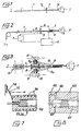
- FIG 1 we see a wire 1 coupled by one of its ends, at point 1a, to a rotary member 2 to impart a twist around its longitudinal axis.
- the wire is subjected to tension T of adjustable intensity. just sufficient to prevent the wire from taking up slack and a maximum value which will depend on the nature, dimensions and characteristics of the wire.
- a member 3 called a torsion locker, has been placed, which has the function of preventing the portion of wire located beyond the locker 3 relative to the drive member 2 from being bent .
- this torsion locking member which must also be able to be moved along the wire 1 in the direction of the distance from the member 2.
- the material constituting the wire 1 will be chosen from natural or synthetic plastically deformable materials. It will preferably be plastics such as linear polymers well known in particular in the plastics industry (polyester, polyethylene, polyamide, polyvinyl, polypropylene, etc.). It can also be natural fibers of animal or vegetable origin.
- the thread can be in the form of a monofilament or a fibrous amalgam.
- the principle of a first embodiment of the method of the invention consists in imparting a twist to the portion of wire between the members 2 and 3 so that a first knot or coil 4 is formed (FIG. 2 ) followed by a second etc ... the wire then taking a helical configuration with contiguous turns.
- This operation can be carried out at room temperature or with the addition of heat in the area of the wire immediately preceding the formation of the nodes and subsequent cooling.
- FIG. 2 a sensor 5 of the position of the last node formed, connected to a control device 6 of a drive member 7 of the locking member 3 along wire 1 in the direction of arrow A.
- FIG. 3 shows a simple embodiment of a locking member 3.
- This consists of a body of revolution 8 (a pulley or a dolly) on which the wire 1 forms at least one dead turn.
- the friction of the wire on this body 8 constitutes the blocking of the torsion.
- This pulley is mounted idle in rotation on an axis 8a to which is attached a stirrup 9 comprising a part 9a turned towards the drive member.
- This part 9a is constantly maintained in contact with the wire by its end 10 and the last knot formed 4 acts on this end 10 by moving the caliper-diabolo assembly away from the member 2.
- the axis 8a which will be called the driving axis, since it cooperates with the thrust yoke 9, can also cooperate with one or more longitudinal guides 11, 12 parallel to the wire 1. This axis can also be coupled to a drive member along these guides (for example member 7 of FIG. 2).
- a body was thus produced in the form of a succession of contiguous turns.
- the configuration obtained is stable and the body constitutes a spring whose elongation can be 100% before reaching a transition point beyond which the turns are destroyed.
- the process described above can include several complementary phases.
- the wire 1 can be heated just before it is twisted (oven symbolized at 13 in FIG. 3 which would, for example, be mobile with the locking device) to a temperature which, for synthetic materials of the plastic type, would be at beyond the glass transition temperature of the product.
- the finished product can then be subjected to a heat treatment (controlled heating and cooling), either to fix the residual distortion by subjecting the product to torsion, or to modify the mechanical and elastic characteristics of the product by subjecting it to this treatment after release of the residual torsion.
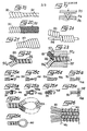
- FIG. 14 shows a first type of product obtained from a base wire 14 which is a monofilament of drawn plastic material. It can be seen that the helical element which is obtained has an outside diameter D of the order of 2.8 times the diameter d of the base wire. The internal diameter of this element Do is of the order of 0.8 times the diameter d above. This geometry is obtained by implementing the process at room temperature.
- FIG. 15 shows a second type of product obtained from an unstretched monofilament base wire 15, that is to say coming directly from the extruder which produces it.
- the implementation of the method on such a wire leads to the product represented in this FIG. 15 which has the particularity of having an internal diameter Do practically zero.
- the outside diameter is substantially equal to twice the diameter of the base wire after shaping, that is to say of diameter restricted to about 0.4 times the diameter do of the starting wire. (D being equal to substantially 0.8 do).
- This product also has a structural characteristic, namely that the fibers forming the material of the basic thread, are, in helical conformation, wound on themselves as shown at 16 in FIGS. 14 to 17.
- This characteristic which confers its nervousness to the product, is sometimes visible in particular when the wire is translucent, and in any case easy to demonstrate by physical and / or chemical means of analysis and control.
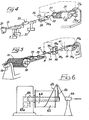
- FIG. 4 we see a diagram illustrating a device for implementing the method described above continuously.
- the output of an extruder from a monofilament wire 21 is shown at 20.
- the latter enters a set of drawing rollers 22 which may include a heat supply device 23.
- the wire 21 then passes over a torsion locking member 24 which can be constituted as previously by a pulley or a dolly whose driving axis 24a can be moved along the wire 21.
- a node detector 25 is placed at the level of the last node formed and is associated with a control device 26 in a manner explained in more detail with reference to FIGS. 7 and 8.
- the helical product then passes through a heat treatment device 27 (which can be an electric oven associated or not to a cooling device) to finally wind up on a storage reel 28 whose rotation around its axis is controlled by a motor 28a while it is mounted on a stirrup 29 itself controlled in rotation by the motor 29a around an axis perpendicular to the axis of the coil.
- a heat treatment device 27 which can be an electric oven associated or not to a cooling device
- the wire 21 is made by one of its ends, integral with the coil 28 through the devices 22 to 27.
- the coil is on the one hand driven in rotation on itself by means of the motor 28a and on the other hand in rotation by means of the motor 29a.
- This last rotation has the effect, like the drive member 2 of Figures 1 to 3, the creation of nodes on the portion of wire between the coil 28 and the locking member 24.
- the position of the last node formed is detected by the member 25 which controls either the speed of the motor 28a (by means of its associated device 26) or the movement of the locker 24 along the wire 21 so that the distance a of Figure 2 is maintained.
- the helical wire will be subjected to a heat treatment by the heating device 27.
- This arrangement will be especially necessary if the basic wire is drawn.
- the characteristics of the final product can be varied by acting on the degree of stretching obtained by the set of rollers 22 and the device 23. It will be advantageous, in this regard to eliminate the stretching, the wire 21 passing directly on the diabolo 24 to obtain a final product according to figure 15.
- the device shown schematically in Figure 5 also allows to implement the first embodiment of the method according to the invention continuously.
- the wire 31 then comes from a reel 30 to be unwound which, being able to rotate around its axis, is mounted on a stirrup 32 itself driven in a rotation movement around an axis perpendicular to the axis of the reel 30, by a motor 33.
- the stirrup carries a device 34 for braking the unwound wire and a torsion lock member 35 on which the wire makes at least one dead turn.
- the product which has become helical passes through a member 38 for immobilizing the torsion and driving downstream of the latter.
- This device could be constituted by two rollers 38a, 38b pinching the product and controlled in rotation by a motor 38c.
- a take-up reel 39 is rotatably mounted about its axis on a stirrup 40 and is coupled to a drive motor 39a.
- the caliper 40 rotates around an axis perpendicular to that of the coil 39 by means of a motor 40a.
- a heat treatment device 41 can be provided upstream of the coil 39.
- the node detector 36 allows by means of the associated device 37 to control the speed of the motor 38c and the motor 39a as a function of the distance to be kept between the last node formed and the locking member 35.
- FIG 6 there is shown a device for twisting the base wire which can be used in place of the device of Figure 5.
- This consists of a coil 42 mounted on a frame to be able to turn and be driven in rotation about its axis by a motor 42a.
- a wire guide 43 On the same axis is mounted in rotation a wire guide 43 which can also be driven by a motor 44 or a multiplier or divider transmission device connected to the drive shaft of the coil.
- the wire 45 passes through a fixed centering guide 46 located in the axis of the coil.
- FIG. 7 is the illustration of an exemplary embodiment of the node detector 36 or 25. It essentially consists of a sleeve 52 mounted to slide on the last nodes formed and which is connected to a fixed part 53 of the frame of the machine by means of a spring leaf 54 on which is placed a strain gauge 55. Exploitation by an appropriate device of the information (and their variation) emitted by the strain gauge makes it possible to create a loop control between the position of the detector and the various motor organs to be controlled (24a, 28a, 38c, 39a) for obtain a stabilization of the desired distance.
- the sleeve 52 may include heating elements 56 and thus play the role of the heat treatment device 27 or 41 of the preceding figures.
- FIG. 8 schematically shows two variants of the node detector of FIG. 7.
- the fixed body 60 of the detector comprises a chamber 61 in which the last nodes formed are housed.
- a pressure is established in the chamber which is detected by a conduit 63.
- This pressure will drop if the nodes leave the chamber 61 and this pressure drop will generate a signal which will be used by the rest of the installation to restore the normal situation in which the nodes are housed in the chamber 61.
- the chamber 61 can have the shape of a flared duct (61 ').
- the value detected will depend on the position of the nodes in the chamber 61 since the latter determines the cross-section of the leaks.
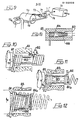
- FIG. 9 is a diagram illustrating a device for implementing the second embodiment of the method according to the invention.
- a coil 70 for unwinding a wire 71 rotatably mounted on a stirrup 72 capable of rotating about an axis perpendicular to the axis of the coil by means of a motor 72a.
- a heat treatment oven 74 is arranged downstream of a locking member or diabolo 73 carried by the stirrup 72.
- a mechanical device of helical conformation of the wire 71 is symbolized.
- This device can be, as shown in FIG. 10, or FIG. 11 constituted by a mandrel 80 for winding the wire 81, rotating around its axis as indicated by the arrow H.
- This mandrel 80 could be slightly conical and its surface will have a relatively low coefficient of friction to allow longitudinal sliding of the turns.
- One or more rollers 82 located at the free end of the mandrel apply the wire wound against a relatively rough surface 80a of the latter (the roughness may consist of longitudinal ridges not forming an obstacle to the above-mentioned axial sliding) so as to help the winding of the wire around the mandrel and its longitudinal progression along the latter.
- a heating means shown diagrammatically at 83 makes it possible to fix the helical deformation.
- the arrow C indicates the direction of the torsional movement imparted to the wire 81, which results in a direction of twist of the fibers indicated at 16, identical to the direction of the helical winding.
- the product thus produced is a helical tension spring with contiguous turns which may have a resistance threshold to extension of a value depending on the intensity of the twist C of the wire.
- FIG. 11 it will be noted that the helical winding being identical to that of FIG. 10, the direction of twist C of the wire and the direction of twist of the fibers are reversed compared to those of FIG. 10.
- the product then obtained is a heli-cold compression spring with non-contiguous turns, the spacing of the turns, and consequently the stiffness, also depends, for a given material, on the intensity of the torsion C.
- FIG. 12 shows a conical mandrel 84 on which a portion of wire 81 has been wound, securing the two ends of this portion on the mandrel.
- a retractable plate 84A in which one end of the wire is threaded.
- Heating means 83 are also used.
- the direction of torsion C is identical to that of FIG.
- a conical helical compression spring is formed which, when it is released from the mandrel 84 takes in the free state the form indicated in phantom in the figure.
- Figures 16 and 17 corresponding respectively to the provisions of Figures 11 and 12.
- the product obtained by the provisions of Figure 10 is to be compared to the product of Figure 14 with any internal diameter depending on the diameter of the mandrel .
- Figures 16A and 16B illus - trent behavior under heat from a coil of the product of Figure 16 from its rest state ( Figure 16A) and after heating (FIG 16B) where there is further a tion INCREASE de d i am tica re , a spacing in the direction parallel to the axis, of the ends of the turn.
- the device 75 in FIG. 9 is shown diagrammatically by a hollow cylinder 85 in the recess 86 from which the wire is introduced tangentially and forced to wind in a helix to escape through the open end 87 of the cylinder.
- the material of the cylinder 85 will be chosen to offer a minimum of friction to the wire. It will be noted that the cylinder 85 has an internal restriction 88 (which could be adjustable) so as to adjust the outside diameter of the product to the desired dimension.
- the twist on itself given to the wire is produced by the rotation of the stirrup 72. It is also advisable to provide at the input of the device 75 a drive member, not shown ( of the type of that of FIG. 5) for scrolling the wire at a speed compatible with the adjustable speed of rotation of the stirrup 72 to obtain a twist of desired value.
- FIG 18 there is shown a helical product 90 from the method according to the invention which has been smoothed the outer surface 91 by any suitable means.
- This means will for example be a "centerless” correction or a hot rolling.
- FIG. 19 illustrates a simple apparatus for obtaining this smoothing. It simply consists of two plates 94 and 95, one of which 94 is provided with a V-shaped groove 96 for guiding the product and the other of which is heated and applied under a certain pressure against the product placed in the groove. A simple rotation on itself of the product in the direction of tightening of the turns causes its advancement between the plates, and the smoothing of its outer surface.
- FIG. 20 shows that the product 90 can be sheathed by means of a braided envelope 92 comparable to that used in the elastic elastomer ties.
- the product 90 can also be wrapped in a flexible film or in an elastic material which is overextruded in a known manner.
- Figure 21 shows that the product 90 similar for example to that shown in Figure 14, can undergo a mechanical expansion operation of its diameter. This operation can be carried out either by chucking (forced expansion of the product on a cone) or by rolling between two internal rollers and an external hot or ambient temperature roller.
- the larger diameter spring thus obtained will have a lower stiffness than the initial product but, on the other hand, a greater elongation power.
- Figure 22 shows that one can obtain a product double helix 93 by combining two products, such as 9 0 and 90a so that a turn of the one being interposed between two turns of the other. We thus obtain products whose elasticity only intervenes beyond a given effort threshold.
- the device is schematized which allows the product of FIG. 22 to be obtained in a simple manner.
- the two products 90 and 9 0 a are introduced into a guide 97 provided with a central orifice 97a opening into an inlet cone 9 7b crossed by a pin 9 8 whose distance from the sides of the cone and at the outlet of the orifice 97a is a function of the diameter of the wire of the products 90 and 90a.
- the "screwing" of the products into each other is obtained by having introduced each of them on one side of the pin 98 and by animating the member 97 with a relative rotation relative to the products around the orifice axis 97 a.
- FIG. 24 illustrates the use of the product of the invention 90 as the sheath of a filiform or tubular element 99 which is housed inside the product. Note that it may be advantageous to sheath a product whose diameter is greater than the above diameter Do in order to obtain a tightening of the sheath on the central element. This advantage is very important when it comes to partially sheathing a cylindrical element over a portion of its length. The tightening thus obtained ensures the maintenance of the sheath on the portion to be protected without having to resort to other fixing means.
- this sheath section can be achieved by means of a tool having a head rotating around the element to be sheathed and delivering the product of the invention around the latter, or driving in rotation the sheathing product and the thus screwing onto the element to be sheathed.
- FIG. 25A shows that a hook 100 can be easily attached to a product 90 screwed in the pitch of the propeller.
- FIG. 25B shows a hook 101 which relates by external screwing to the end of the spring 90.
- a central pin 101a is provided which keeps product 90 at its nominal diameter.
- the hook 102 is forcibly introduced and retained by its rod in the form of crampons in the product 90.
- the hook 1 0 3 in FIG. 25D has tongues 103a serving as unidirectional crampons allowing the fitting and opposing the extraction.
- the hook 104 of Figure 25 E is formed by the wire itself while that 105 of Figure 25F is reported by overmolding.
- the end of the spring 90 is welded to a plate 106 (FIG. 2 5G ) while the end 107 of the spring 90 of FIG. 25H is deformed when hot to form a retaining stop after passing through the orifice of a plate. 108.
- FIG. 251 shows that it is easy to form a loop 109 by associating the free end of the product 90 with a section of the latter as in the case of FIG. 22.
- the loop 110 is formed by a section of helically non-deformed wire situated between two deformed sections, one of which is used, by association with the other according to the diagram of FIGS. 22 and 23, to close the loop.
- FIG. 26 schematically illustrates the application of the product of the invention to the field of weaving. It can be seen that it is easy to constitute an elastic band 111 in which the warp threads are constituted by helical products 90, placed side by side, having taken care to alternate the helix directions of each product as well as possible. '' avoid further deformation of the entire woven strip, and joined by a weft thread 112, elastic or not.
- the products according to the invention have many advantages. These include their quality of inalterability due to the material used when it is made of plastic. Their elastic characteristic is linear and is advantageously placed between that of the metal springs and that of the elastomer fibers which it is not linear. Furthermore, the section of the base wire can be circular, polygonal, elliptical.
- the material which composes it can be composite and comprise for example in the vicinity of its neutral fiber a material of a different nature from that of the wire. This material may be either an electrically conductive filament, or simply a recess. We can also consider the installation of an optical fiber or a magnetic fiber ... Finally, the fields of application are very wide and varied passing through textile or similar products, vibrating strings, racket strings tennis, cladding, strapping, sporting goods, industrial mechanisms, car and outdoor seats including furniture, bedding, some medical equipment ....
- the invention finds an interesting application in the field of elastic elements.
Landscapes
- Engineering & Computer Science (AREA)
- Mechanical Engineering (AREA)
- General Engineering & Computer Science (AREA)
- Textile Engineering (AREA)
- Wire Processing (AREA)
- Shaping Of Tube Ends By Bending Or Straightening (AREA)
Applications Claiming Priority (4)
| Application Number | Priority Date | Filing Date | Title |
|---|---|---|---|
| FR8303921 | 1983-03-10 | ||
| FR8303921A FR2542331B1 (fr) | 1983-03-10 | 1983-03-10 | Procede et dispositif de fabrication d'un element elastique a partir d'un fil non metallique plastiquement deformable. ressort helicoidal issu du procede |
| FR8320763 | 1983-12-23 | ||
| FR8320763 | 1983-12-26 |
Publications (2)
| Publication Number | Publication Date |
|---|---|
| EP0122828A1 true EP0122828A1 (de) | 1984-10-24 |
| EP0122828B1 EP0122828B1 (de) | 1988-02-17 |
Family
ID=26223322
Family Applications (1)
| Application Number | Title | Priority Date | Filing Date |
|---|---|---|---|
| EP19840400493 Expired EP0122828B1 (de) | 1983-03-10 | 1984-03-12 | Verfahren und Vorrichtung zur Herstellung eines schraubenförmigen Produktes wie eine Feder aus Kunststoff |
Country Status (4)
| Country | Link |
|---|---|
| EP (1) | EP0122828B1 (de) |
| AU (1) | AU2536184A (de) |
| DE (1) | DE3469381D1 (de) |
| WO (1) | WO1984003545A1 (de) |
Cited By (2)
| Publication number | Priority date | Publication date | Assignee | Title |
|---|---|---|---|---|
| EP1563212A4 (de) * | 2002-10-23 | 2005-12-07 | Stopak Pty Ltd | Aufblasventil |
| EP4065339A4 (de) * | 2019-11-25 | 2024-04-17 | Nanyang Technological University | Verfahren zur herstellung einer faser, faseraktuatoren, faserbündel und verfahren zur herstellung des faserbündels |
Families Citing this family (3)
| Publication number | Priority date | Publication date | Assignee | Title |
|---|---|---|---|---|
| US5111849A (en) * | 1988-12-29 | 1992-05-12 | Ems-Inventa Ag | Helical pipes and method of manufacture thereof |
| US7441758B2 (en) | 2004-06-17 | 2008-10-28 | Illinois Tool Works Inc. | Load bearing surface |
| WO2011034882A1 (en) * | 2009-09-16 | 2011-03-24 | Illinois Tool Works Inc. | Pre-deformed thermoplastics spring and method of manufacture |
Citations (8)
| Publication number | Priority date | Publication date | Assignee | Title |
|---|---|---|---|---|
| US2392842A (en) * | 1943-06-10 | 1946-01-15 | Du Pont | Method of making coiled structures |
| US2432935A (en) * | 1946-02-05 | 1947-12-16 | Us Rubber Co | Apparatus for making coiled yarn |
| FR1085331A (fr) * | 1953-10-21 | 1955-01-31 | Ressort en verre filé | |
| FR1303358A (fr) * | 1961-10-11 | 1962-09-07 | Glanzstoff Ag | Procédé pour le frisage de fils à filaments multiples par fixage d'une torsion appliquée temporairement et appareil pour la mise en oeuvre de ce procédé |
| GB1083481A (en) * | 1964-03-07 | 1967-09-13 | Lb Plastics Ltd | Method for producing helical or annular formations in plastics |
| US4198459A (en) * | 1976-12-03 | 1980-04-15 | Brumlik George C | Filaments with evolved structure and process of making some |
| US4201813A (en) * | 1976-01-14 | 1980-05-06 | Brumlik George C | Cellular linear filaments with transverse partitions |
| GB2056615A (en) * | 1979-07-12 | 1981-03-18 | Exxon Research Engineering Co | Fiber-reinforced coil spring |
-
1984
- 1984-03-07 AU AU25361/84A patent/AU2536184A/en not_active Abandoned
- 1984-03-12 DE DE19843469381 patent/DE3469381D1/de not_active Expired
- 1984-03-12 WO PCT/FR1984/000058 patent/WO1984003545A1/fr not_active Ceased
- 1984-03-12 EP EP19840400493 patent/EP0122828B1/de not_active Expired
Patent Citations (8)
| Publication number | Priority date | Publication date | Assignee | Title |
|---|---|---|---|---|
| US2392842A (en) * | 1943-06-10 | 1946-01-15 | Du Pont | Method of making coiled structures |
| US2432935A (en) * | 1946-02-05 | 1947-12-16 | Us Rubber Co | Apparatus for making coiled yarn |
| FR1085331A (fr) * | 1953-10-21 | 1955-01-31 | Ressort en verre filé | |
| FR1303358A (fr) * | 1961-10-11 | 1962-09-07 | Glanzstoff Ag | Procédé pour le frisage de fils à filaments multiples par fixage d'une torsion appliquée temporairement et appareil pour la mise en oeuvre de ce procédé |
| GB1083481A (en) * | 1964-03-07 | 1967-09-13 | Lb Plastics Ltd | Method for producing helical or annular formations in plastics |
| US4201813A (en) * | 1976-01-14 | 1980-05-06 | Brumlik George C | Cellular linear filaments with transverse partitions |
| US4198459A (en) * | 1976-12-03 | 1980-04-15 | Brumlik George C | Filaments with evolved structure and process of making some |
| GB2056615A (en) * | 1979-07-12 | 1981-03-18 | Exxon Research Engineering Co | Fiber-reinforced coil spring |
Cited By (2)
| Publication number | Priority date | Publication date | Assignee | Title |
|---|---|---|---|---|
| EP1563212A4 (de) * | 2002-10-23 | 2005-12-07 | Stopak Pty Ltd | Aufblasventil |
| EP4065339A4 (de) * | 2019-11-25 | 2024-04-17 | Nanyang Technological University | Verfahren zur herstellung einer faser, faseraktuatoren, faserbündel und verfahren zur herstellung des faserbündels |
Also Published As
| Publication number | Publication date |
|---|---|
| DE3469381D1 (de) | 1988-03-24 |
| EP0122828B1 (de) | 1988-02-17 |
| WO1984003545A1 (fr) | 1984-09-13 |
| AU2536184A (en) | 1984-09-13 |
Similar Documents
| Publication | Publication Date | Title |
|---|---|---|
| EP0204607B1 (de) | Kunststoffmast zum Tragen von insbesondere elektrischen Leitungen und Vorrichtung zum Wickeln von Fasern um diesen Mast | |
| CH424072A (fr) | Procédé de fabrication d'un fil formé d'un ou plusieurs filaments synthétiqués continus en polymère thermoplastique, et appareil pour la mise en oeuvre du procédé | |
| EP2807296B1 (de) | Hybrides elastisches kabel und verfahren zur herstellung eines solchen kabels | |
| FR2508374A1 (fr) | Procede permettant de former des rainures longitudinales sur un filament en materiau thermoplastique ou a la surface d'un corps cylindrique allonge | |
| FR2547067A1 (fr) | Procede et installation pour donner a une fibre une longueur additionnelle dans le revetement secondaire d'une fibre optique | |
| FR1465787A (fr) | Filés comportant une âme, procédé et appareil pour les fabriquer | |
| EP0122828B1 (de) | Verfahren und Vorrichtung zur Herstellung eines schraubenförmigen Produktes wie eine Feder aus Kunststoff | |
| FR2473574A1 (fr) | Procede et machine de fabrication de cables ouverts | |
| FR2840624A1 (fr) | Appareil de fabrication de fils | |
| EP1646740B1 (de) | Maschine zum kontinuierlichen fachen, zwirnen und fixieren von fäden | |
| FR3059988B1 (fr) | Procede et machine pour l'enroulement d'un element filaire autour d'une piece pour le frettage, l'enroulement filamentaire ou le marouflage | |
| EP0070210A1 (de) | Verfahren und Vorrichtung zur Herstellung eines Hülle-Kern-Garns | |
| FR2542331A1 (fr) | Procede et dispositif de fabrication d'un element elastique a partir d'un fil non metallique plastiquement deformable. ressort helicoidal issu du procede | |
| CH678232A5 (de) | ||
| EP2418308A1 (de) | Verfahren und Vorrichtung zur Fadentexturierung für Teppiche oder Teppichböden, die einer Wärmebehandlung vorgeschaltet ist | |
| BE412704A (de) | ||
| FR2715445A1 (fr) | Ressort précontraint et procédé et dispositif pour sa fabrication, et application du ressort à un enrouleur de câble. | |
| BE680627A (de) | ||
| BE841724A (fr) | Cable de renforcement pour articles elastomeres et procede et appareil pour fabriquer ces cables | |
| BE549640A (de) | ||
| WO2005061767A2 (fr) | Dispositif de traitement thermique d'un fil textile en mouvement | |
| BE554482A (de) | ||
| CH359511A (fr) | Machine pour donner une fausse torsion à un fil | |
| BE630235A (de) | ||
| BE563452A (de) |
Legal Events
| Date | Code | Title | Description |
|---|---|---|---|
| PUAI | Public reference made under article 153(3) epc to a published international application that has entered the european phase |
Free format text: ORIGINAL CODE: 0009012 |
|
| AK | Designated contracting states |
Designated state(s): BE DE FR GB IT NL SE |
|
| 17P | Request for examination filed |
Effective date: 19850423 |
|
| RAP1 | Party data changed (applicant data changed or rights of an application transferred) |
Owner name: SIMONIN & CIE S.A. |
|
| 17Q | First examination report despatched |
Effective date: 19860210 |
|
| D17Q | First examination report despatched (deleted) | ||
| GRAA | (expected) grant |
Free format text: ORIGINAL CODE: 0009210 |
|
| AK | Designated contracting states |
Kind code of ref document: B1 Designated state(s): BE DE FR GB IT NL SE |
|
| ITF | It: translation for a ep patent filed | ||
| REF | Corresponds to: |
Ref document number: 3469381 Country of ref document: DE Date of ref document: 19880324 |
|
| GBT | Gb: translation of ep patent filed (gb section 77(6)(a)/1977) | ||
| PLBE | No opposition filed within time limit |
Free format text: ORIGINAL CODE: 0009261 |
|
| STAA | Information on the status of an ep patent application or granted ep patent |
Free format text: STATUS: NO OPPOSITION FILED WITHIN TIME LIMIT |
|
| 26N | No opposition filed | ||
| PGFP | Annual fee paid to national office [announced via postgrant information from national office to epo] |
Ref country code: GB Payment date: 19910301 Year of fee payment: 8 |
|
| PGFP | Annual fee paid to national office [announced via postgrant information from national office to epo] |
Ref country code: SE Payment date: 19910318 Year of fee payment: 8 |
|
| PGFP | Annual fee paid to national office [announced via postgrant information from national office to epo] |
Ref country code: BE Payment date: 19910328 Year of fee payment: 8 |
|
| ITTA | It: last paid annual fee | ||
| PGFP | Annual fee paid to national office [announced via postgrant information from national office to epo] |
Ref country code: NL Payment date: 19910331 Year of fee payment: 8 |
|
| PGFP | Annual fee paid to national office [announced via postgrant information from national office to epo] |
Ref country code: DE Payment date: 19910412 Year of fee payment: 8 |
|
| PG25 | Lapsed in a contracting state [announced via postgrant information from national office to epo] |
Ref country code: GB Effective date: 19920312 |
|
| PG25 | Lapsed in a contracting state [announced via postgrant information from national office to epo] |
Ref country code: SE Effective date: 19920313 |
|
| PG25 | Lapsed in a contracting state [announced via postgrant information from national office to epo] |
Ref country code: BE Effective date: 19920331 |
|
| BERE | Be: lapsed |
Owner name: S.A. SIMONIN & CIE Effective date: 19920331 |
|
| PG25 | Lapsed in a contracting state [announced via postgrant information from national office to epo] |
Ref country code: NL Effective date: 19921001 |
|
| GBPC | Gb: european patent ceased through non-payment of renewal fee | ||
| NLV4 | Nl: lapsed or anulled due to non-payment of the annual fee | ||
| PG25 | Lapsed in a contracting state [announced via postgrant information from national office to epo] |
Ref country code: DE Effective date: 19921201 |
|
| EUG | Se: european patent has lapsed |
Ref document number: 84400493.7 Effective date: 19921005 |
|
| PGFP | Annual fee paid to national office [announced via postgrant information from national office to epo] |
Ref country code: FR Payment date: 19980312 Year of fee payment: 15 |
|
| PG25 | Lapsed in a contracting state [announced via postgrant information from national office to epo] |
Ref country code: FR Free format text: LAPSE BECAUSE OF NON-PAYMENT OF DUE FEES Effective date: 19991130 |
|
| REG | Reference to a national code |
Ref country code: FR Ref legal event code: ST |