EP0122890A1 - Ankoppelvorrichtung für Raumflugkörper - Google Patents
Ankoppelvorrichtung für Raumflugkörper Download PDFInfo
- Publication number
- EP0122890A1 EP0122890A1 EP84830105A EP84830105A EP0122890A1 EP 0122890 A1 EP0122890 A1 EP 0122890A1 EP 84830105 A EP84830105 A EP 84830105A EP 84830105 A EP84830105 A EP 84830105A EP 0122890 A1 EP0122890 A1 EP 0122890A1
- Authority
- EP
- European Patent Office
- Prior art keywords
- coupling
- docking system
- docking
- modules
- shank
- Prior art date
- Legal status (The legal status is an assumption and is not a legal conclusion. Google has not performed a legal analysis and makes no representation as to the accuracy of the status listed.)
- Granted
Links
Images



Classifications
-
- B—PERFORMING OPERATIONS; TRANSPORTING
- B64—AIRCRAFT; AVIATION; COSMONAUTICS
- B64G—COSMONAUTICS; VEHICLES OR EQUIPMENT THEREFOR
- B64G1/00—Cosmonautic vehicles
- B64G1/22—Parts of, or equipment specially adapted for fitting in or to, cosmonautic vehicles
- B64G1/64—Systems for coupling or separating cosmonautic vehicles or parts thereof, e.g. docking arrangements
- B64G1/646—Docking or rendezvous systems
- B64G1/6462—Docking or rendezvous systems characterised by the means for engaging other vehicles
- B64G1/6464—Docking probes and receivers
-
- B—PERFORMING OPERATIONS; TRANSPORTING
- B64—AIRCRAFT; AVIATION; COSMONAUTICS
- B64G—COSMONAUTICS; VEHICLES OR EQUIPMENT THEREFOR
- B64G1/00—Cosmonautic vehicles
- B64G1/22—Parts of, or equipment specially adapted for fitting in or to, cosmonautic vehicles
- B64G1/64—Systems for coupling or separating cosmonautic vehicles or parts thereof, e.g. docking arrangements
- B64G1/648—Tethers
-
- F—MECHANICAL ENGINEERING; LIGHTING; HEATING; WEAPONS; BLASTING
- F16—ENGINEERING ELEMENTS AND UNITS; GENERAL MEASURES FOR PRODUCING AND MAINTAINING EFFECTIVE FUNCTIONING OF MACHINES OR INSTALLATIONS; THERMAL INSULATION IN GENERAL
- F16B—DEVICES FOR FASTENING OR SECURING CONSTRUCTIONAL ELEMENTS OR MACHINE PARTS TOGETHER, e.g. NAILS, BOLTS, CIRCLIPS, CLAMPS, CLIPS OR WEDGES; JOINTS OR JOINTING
- F16B2200/00—Constructional details of connections not covered for in other groups of this subclass
- F16B2200/30—Dovetail-like connections
Definitions
- the object of the present invention is to provide a docking system of the said type which is particularly functional and reliable.
- the expandible head of the coupling shank is substantially spherical and the coupling seat intended to cooperate with this expandible head has a corresponding shape.
- the said coupling shank has a tubular body with, in correspondence with the head, a series of longitudinal slits which define a plurality of petal sectors which are resiliently outwardly flexible.
- the inner faces of the petal sectors define a substantially conical surface converging towards the end of the shank, so as to allow the expansion of these petal sectors by means of a thrust member slidably mounted within these sectors.
- An infra-red radiation indicator system is also provided to facilitate the mutual approach into the centered condition of the two coupling members of the docking device.
- the various members constituting the docking system 3 are carried by two triangular plates 4, 5 fixed to the two space modules 1, 2 respectively.
- the docking system 3 includes a docking device constituted by respective male and female coupling members 6, 7 carried by the two space modules.
- the two coupling members 6, 7 are shaped so as to allow,after they have been brought into their coupled condition, relative rotation of the two space modules about the axis X-X of the docking device.
- the docking system 3 further includes a plurality (three in the example illustrated) of connecting devices 8 arranged to lock the two space modules 1, 2 in a precise relative position after the male and female members 6, 7 of the docking device have been brought into their coupled condition.
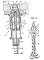
- Each connecting device 8 comprises a coupling seat 9 which, in the example illustrated is defined by the internal cavity of an annulus 10 fixed to the module 1, and a coupling shank 11 carried by the space module 2.
- Each coupling shank 11 is movable axially between a withdrawn inoperative position and an extended coupling position, as will be explained in more detail below.
- each coupling shank 11 has a head 12 which can expand within the corresponding seat 9 to effect the connection between the two space modules 1, 2.
- the coupling shank 11 is constituted by a tubular body having an expandible head 12 of substantially spherical shape arranged to cooperate with a seat 9 of corresponding shape.
- the coupling shank 11 has a tubular body with, in correspondence with the head 12, a plurality of longitudinal slits 13 which define a series of petal sectors 14 which are resiliently outwardly flexible.
- the inner faces of the petal sectors 14 define a substantially conical surface converging towards the end of the coupling shank 11, within which is slidable a thrust member 15 intended to effect the expansion of the petal sectors 14, as will be explained below.
- the shank 11 is slidable axially by means of a splined coupling 16 within a casing 17 which is fixed to the space module 2 (see Figure 1).
- the casing 17 has a flange 18 for fixing it to the plate 5.
- An auxiliary member 20 having a tubular coaxial shank 11 internally threaded spigot 21 is slidable within the coupling shank 11.
- the internally threaded hole of the spigot 21 is engaged by one end of a screw 22 which is rotatably supported within the casing 17 by means of taper roller bearings 23 and which-is driven by an electric motor 24 fixed to the casing 17.
- the end of the spigot 21 opposite the screw 22 is connected by a ball joint to the thrust member 15.
- the thrust member 15 has an end lug with a spherical head 25 which engages in a spherical seat formed in the end of the spigot 21 and is locked in this position by means of a cap element 26 screwed onto the spigot 21.
- each docking device 8 is as follows:
- the motor 24 is supplied with a higher current. Since the shank 11 can no longer move because of the abutment shoulder 19, the slidable member 20 moves relative to the shank 11,thrusting the element 15 towards the end of the head 12 and consequently causing the opening of the petal sectors 14 as illustrated in Figure 4.
- the supply current for the motor 24 is further increased so as to apply a torque locking the member 15 between the petals 14.
- the electric motor 24 is de-energised.
- the ball joint 25 allows small movements of adjustment of the petal sectors 14 upon introduction into the seat 9 in the case of non-perfect alignment.
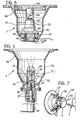
- FIGS 5, 6 illustrate the two male and female coupling members 6, 7 constituting the docking device.
- the female coupling member 6 has a flared body with a conical mouth 28 connected by means of a cylindrical portion 29 to a conical portion 30 the internal surface 31 of which constitutes one of the two conical coupling surfaces of the docking device.
- a tubular spigot 32 within which an element 33 is slidable.
- a key 34 prevents rotation of the element 33 relative to the spigot 32.
- the element 33 has a threaded hole 35 within which is engaged a screw 36 which is rotatably supported within the body of the coupling member 6 by taper roller bearings 37.
- the screw 36 is driven by an electric motor 38 fixed to the body of the coupling member.
- the element 33 has three resilient tabs 39 (only one of which is visible in Figure 5) which are equiangularly spaced. These resilient tabs are intended to cooperate with a corresponding seat of the coupling member 7 to achieve the locking of the two members 6, 7 in the coupled condition, as will emerge from the description below.
- the coupling member 6 has an infra-red radiation transmitter 40which will also be described below.
- the end portion 41 of the coupling member 7 has a hole 45 within which a bush 46 is rotatable with the interposition of a rolling bearing 47.
- the internal ring of the bearing 47 is axially fixed to the bush 46, being mounted between a resilient ring 48 fixed to the bush 46 and a shoulder 49 of the bush.
- the outer ring of the bearing 47 is mounted between a resilient ring 50 fixed to the body of the coupling member 7 and a pair of cup springs 51 which are interposed between the bearing 47 and the bottom of the bearing seat.
- the internal surface of the bush 46 has a cylindrical portion 52 of smaller diameter connected to the ends by two conical portions 53, 54.
- the coupling member 7 is finally provided with an infra-red radiation receiver 55 intended to cooperate with the transmitter 40 of the coupling member 6 the function of which will be explained below.
- Figure 7 relates to a first docking procedure which consists simply in moving the two space modules 1, 2 towards each other at slow speed until the two conical coupling surfaces 31, 42 are brought into contact with each other in the manner which has been described above.
- This procedure involves the use of a conical mouth 28 for the coupling member 6 of a relatively large width to take account of possible misalignments.
- the two coupling members 6, 7 have reference means for the correct angular positioning of the two modules.
- These reference means may be constituted, for example, by a reference bar 55 carried by the coupling member 7 and arranged to cooperate with a reference groove 56 of the coupling member 6.
- the coupling member 6 is connected to the space module 1 by means of a series of shock absorber elements 57.
- the two space modules are thrust towards each other at slow speed with the pylon 58 in the extended position until the conical coupling surfaces 31, 41 come into contact with each other.
- the pylon 58 is able to damp the collision so as to achieve "soft" docking.
- Reference numeral 59 indicates the radar system mentioned above, necessary for the final approach phase which in this case is disposed at the end of the pylon 58.
- Figure 9 relates to a third docking technique.
- the coupling member is also disposed at the top of a retractable pylon similar to the pylon 58 of Figure 8 (not illustrated in Figure 9).
- each of the two coupling members 6, 7 is provided with a retractable probe 60 constituted, for example, by a rigid strip which may wind or unwind from a winding device 61 the free ends of the two probes 60 having hooks 62 for their mutual coupling.
- the two space modules are brought close to each other and stopped at a distance of a few metres (for example 3 metres).
- the pylon carrying the coupling member 7 is then extended, and the two probes 60 are also extended and then connected together.
- theprobe 60 carried by the coupling member 6 is rotated about the axis of the coupling member so as to describe conical surfaces of a diameter which gradually decreases until hooking of the two ends 62 is achieved.
- the two probes 60 are retracted into the members 6, 7 and these latter are rotated relative to each other so as to bring the connecting devices 8 into the aligned condition.
- the reference for the correct angular position is achieved by forming the conical coupling surfaces with a section which is not exactly circular but slightly elliptical.
- Figures 10 to 12 illustrate schematically the principle of operation of the infra-red radiation indicator system which is used as an aid during the final approach phase to achieve the correct aligned position of the two coupling members 6, 7.
- the structure of the infra-red radiation system is also illustrated schematically in Figures 5, 6.
- the system comprises an infra-red radiation transmitter 40 which comprises an infra-red radiation source , an electronic supply and an objective for correction and adjustment of the radiation.
- the system also includes an infra-red radiation receiver 55 (see Figure 6) carried by the coupling member 7 comprising an objective 63 and a mirror 64 inclined to a plane perpendicular to the axis of the coupling member and rotated about this axis by means of an electric motor 65.
- the mirror 64 reflects radiation focussed at a point 65 on the internal surface 66 of the objective 63.
- the point 65 moves along a circle on the surface G6 because of the rotational movement of the mirror 64.
- the objective 63 On the inner side of the objective 63 moreover, there are located four infra-red detectors which cover the four quadrants of the objective respectively.
- Figure 10 illustrates a possible condition of misalignment of the two coupling members 6, 7.
- the axes of the two members 6, 7 are parallel and spaced apart whereby the receiver 55 sees the transmitter 40 with an angle of inclination E relative to the axis of alignment.
- the inclination see Ficure 12
- thecircledescribed by the point 65 on the inner surface of the objective 66 is not concentric with this objective since it comprises arcs of different length in correspondence with the four quadrants. This means that the point 65 remains in each quadrant for a different time. This situation is detected by the fact that the electrical output voltage signal from each infra-red detector is proportional to the time during which the focussed radiation stays in each quadrant.
- Figure 12 illustrates schematically the four quadrants (indicated by the letters A, B , C and D)and the circle described by the focussed radiation in the case of a misalignment of the type illustrated in Figure 10. If V At V B , V C and V D are output voltage signalsfrom the infra-red detectors corresponding to the four quadrants, the distances of misalignment ⁇ x and ⁇ y along the axes X and Y are proportional respectively to the following voltages:
- Figure 11 illustrates another condition of misalignment in which the two axes of the coupling members 6, 7 are not parallel but intersect each other.
- the receiver 55 sees the transmitter 40 with an angle equal to zero, but the emission diagram of the infra-red radiation is rotated.
- the output signals from the infra-red detectors are lower than when the coupling members 6, 7 are aligned.
- the angled of misalignment is consequently formed by a comparison of the output signals from the infra-red detectors with a predetermined level corresponding to the aligned condition.
- This also means that the circle described by the point 65 on the objective has a lower luminosity than that which it would have in the aligned condition.
Landscapes
- Engineering & Computer Science (AREA)
- Remote Sensing (AREA)
- Aviation & Aerospace Engineering (AREA)
- Pivots And Pivotal Connections (AREA)
- Measuring Pulse, Heart Rate, Blood Pressure Or Blood Flow (AREA)
- Coupling Device And Connection With Printed Circuit (AREA)
- Selective Calling Equipment (AREA)
- Input Circuits Of Receivers And Coupling Of Receivers And Audio Equipment (AREA)
- Fittings On The Vehicle Exterior For Carrying Loads, And Devices For Holding Or Mounting Articles (AREA)
- Chairs For Special Purposes, Such As Reclining Chairs (AREA)
Priority Applications (1)
| Application Number | Priority Date | Filing Date | Title |
|---|---|---|---|
| AT84830105T ATE25835T1 (de) | 1983-04-19 | 1984-04-09 | Ankoppelvorrichtung fuer raumflugkoerper. |
Applications Claiming Priority (2)
| Application Number | Priority Date | Filing Date | Title |
|---|---|---|---|
| IT6742683 | 1983-04-19 | ||
| IT67426/83A IT1193427B (it) | 1983-04-19 | 1983-04-19 | Sistema di aggancio docking per moduli spaziali |
Publications (2)
| Publication Number | Publication Date |
|---|---|
| EP0122890A1 true EP0122890A1 (de) | 1984-10-24 |
| EP0122890B1 EP0122890B1 (de) | 1987-03-11 |
Family
ID=11302286
Family Applications (1)
| Application Number | Title | Priority Date | Filing Date |
|---|---|---|---|
| EP84830105A Expired EP0122890B1 (de) | 1983-04-19 | 1984-04-09 | Ankoppelvorrichtung für Raumflugkörper |
Country Status (5)
| Country | Link |
|---|---|
| US (1) | US4607815A (de) |
| EP (1) | EP0122890B1 (de) |
| AT (1) | ATE25835T1 (de) |
| DE (1) | DE3462592D1 (de) |
| IT (1) | IT1193427B (de) |
Cited By (11)
| Publication number | Priority date | Publication date | Assignee | Title |
|---|---|---|---|---|
| WO1987002797A1 (en) * | 1985-10-31 | 1987-05-07 | Energy Optics, Inc. | Dead reckoning optoelectronic intelligent docking system |
| FR2593466A1 (fr) * | 1985-10-30 | 1987-07-31 | Rca Corp | Structure de vehicule spatial permettant l'assemblage et le depannage en orbite |
| DE3609770A1 (de) * | 1986-03-22 | 1987-10-01 | Erno Raumfahrttechnik Gmbh | Nutzlasttransport- und -betriebseinrichtung fuer raumfahrzeuge |
| DE3613985A1 (de) * | 1986-04-25 | 1987-10-29 | Erno Raumfahrttechnik Gmbh | Nutzlastbehaelter und nutzlastbehaelter-befestigungsvorrichtung fuer raumfahrzeuge |
| WO1988001752A1 (en) * | 1986-09-02 | 1988-03-10 | Hughes Aircraft Company | Off axis optical communication system |
| EP0358058A1 (de) * | 1988-08-29 | 1990-03-14 | Honeywell Inc. | Arretiersystem |
| EP0537623A3 (en) * | 1991-10-14 | 1993-09-01 | Mitsubishi Denki Kabushiki Kaisha | Rendezvous docking optical sensor system |
| US5868358A (en) * | 1996-04-22 | 1999-02-09 | Mitsubishi Denki Kabushiki Kaisha | Rendezvous spacecraft collision avoidance device |
| JP2017109734A (ja) * | 2015-12-11 | 2017-06-22 | 国立研究開発法人宇宙航空研究開発機構 | 結合装置 |
| IT201800010623A1 (it) * | 2018-11-27 | 2020-05-27 | Italdesign Giugiaro Spa | Sistema di trasporto modulare per il trasporto di persone od oggetti. |
| IT201800010619A1 (it) * | 2018-11-27 | 2020-05-27 | Italdesign Giugiaro Spa | Sistema di trasporto modulare per il trasporto di persone od oggetti. |
Families Citing this family (34)
| Publication number | Priority date | Publication date | Assignee | Title |
|---|---|---|---|---|
| US4929011A (en) * | 1988-02-04 | 1990-05-29 | National Research Counsil Of Canada/Conseil National De Recherches Du Canada | Grapple fixture |
| US4905938A (en) * | 1988-07-01 | 1990-03-06 | General Electric Company | Special purpose robotic end effector |
| US4989818A (en) * | 1989-06-13 | 1991-02-05 | Tennessee Valley Authority | Nozzle dam remote installation system and technique |
| US5046691A (en) * | 1989-09-05 | 1991-09-10 | Trw Inc. | ORU latch |
| US5253944A (en) * | 1991-08-22 | 1993-10-19 | Hughes Aircraft Company | Precision alignment and mounting apparatus |
| US5167464A (en) * | 1991-10-07 | 1992-12-01 | The United States Of America As Represented By The Administrator Of The Natoinal Aeronautics And Space Administration | High-repeatability, robot friendly, ORU interface |
| US5364046A (en) * | 1992-02-24 | 1994-11-15 | Environmental Research Institute Of Michigan | Automatic compliant capture and docking mechanism for spacecraft |
| US5271286A (en) * | 1992-09-17 | 1993-12-21 | The United States Of America As Represented By The Administrator Of The National Aeronautics And Space Administration | Spline screw multiple rotations mechanism |
| US5522569A (en) * | 1994-02-04 | 1996-06-04 | Orbital Sciences Corporation | Satellite having a stackable configuration |
| RU2222480C2 (ru) * | 2001-10-10 | 2004-01-27 | Открытое акционерное общество "Ракетно-космическая корпорация "Энергия" им. С.П.Королева" | Устройство стыковки развертываемых модулей космических аппаратов |
| US7857261B2 (en) * | 2001-11-01 | 2010-12-28 | Michigan Aerospace Corporation | Docking system |
| US7104505B2 (en) * | 2001-11-01 | 2006-09-12 | Michigan Aerospace Corporation | Autonomous satellite docking system |
| US6767155B2 (en) * | 2002-04-05 | 2004-07-27 | Eastman Kodak Company | High stability latch mechanism |
| US6945500B2 (en) * | 2003-08-15 | 2005-09-20 | Skycorp, Inc. | Apparatus for a geosynchronous life extension spacecraft |
| RU2269462C2 (ru) * | 2003-10-06 | 2006-02-10 | Открытое акционерное общество "Ракетно-космическая корпорация "Энергия" им. С.П. Королева" | Устройство стыковки космических модулей |
| ITBO20030724A1 (it) * | 2003-11-28 | 2005-05-29 | Vima Impianti S R L | Apparecchiatura per la movimentazione di contenitori. |
| US20050263649A1 (en) * | 2004-03-18 | 2005-12-01 | Michigan Aerospace Corporation | Autonomous vehicle docking system |
| US7861974B2 (en) * | 2004-03-18 | 2011-01-04 | Michigan Aerospace Corporation | Docking system |
| US7828249B2 (en) * | 2004-03-18 | 2010-11-09 | Michigan Aerospace Corporation | Docking system |
| US8240613B2 (en) * | 2004-03-18 | 2012-08-14 | Michigan Aerospace Corporation | Docking system |
| US8245370B2 (en) * | 2004-03-18 | 2012-08-21 | Michigan Aerospace Corporation | Docking system |
| US7850388B2 (en) * | 2006-04-07 | 2010-12-14 | University Of Southern California | Compliant, low profile, independently releasing, non-protruding and genderless docking system for robotic modules |
| US7118077B1 (en) * | 2005-03-11 | 2006-10-10 | Kistler Walter P | Platform and system for mass storage and transfer in space |
| US7374134B2 (en) * | 2005-08-29 | 2008-05-20 | Honeywell International Inc. | Systems and methods for semi-permanent, non-precision inspace assembly of space structures, modules and spacecraft |
| DE102008061977B4 (de) * | 2008-12-12 | 2010-09-02 | Deutsches Zentrum für Luft- und Raumfahrt e.V. | Vorrichtung zum Andocken eines Service-Satelliten an einen Zielsatelliten |
| US8985219B2 (en) * | 2010-11-22 | 2015-03-24 | Onesubsea, Llc | System and method for connection and installation of underwater lines |
| WO2016030890A1 (en) | 2014-08-26 | 2016-03-03 | Effective Space Solutions Ltd | Docking system and method for satellites |
| CN104614987B (zh) * | 2014-12-19 | 2017-04-05 | 中国空间技术研究院 | 一种用于高轨卫星锥杆式抓捕机构的实时控制系统及方法 |
| JP6722514B2 (ja) * | 2016-05-27 | 2020-07-15 | 株式会社アストロスケール | 捕獲プレート、宇宙用装置及び捕獲方法 |
| US10625882B2 (en) | 2017-03-06 | 2020-04-21 | Effective Space Solutions Ltd. | Service satellite for providing in-orbit services using variable thruster control |
| US12214912B2 (en) * | 2020-05-20 | 2025-02-04 | Honeybee Robotics, Llc | In-space grasping system and method of operation |
| CN111717418B (zh) * | 2020-07-21 | 2023-09-19 | 哈尔滨工业大学 | 半主动控制式星球车对接系统及对接方法 |
| CN114227210B (zh) * | 2022-02-24 | 2022-05-17 | 中国空气动力研究与发展中心高速空气动力研究所 | 基于气弹簧的六自由度自适应位姿调整对接装置及方法 |
| CN115892523B (zh) * | 2022-10-27 | 2025-08-08 | 南京航空航天大学 | 一种微纳卫星电磁对接机构及其设计方法 |
Citations (5)
| Publication number | Priority date | Publication date | Assignee | Title |
|---|---|---|---|---|
| US3224709A (en) * | 1962-09-13 | 1965-12-21 | Martin Marietta Corp | Method and apparatus for docking vehicles |
| US3424403A (en) * | 1967-02-14 | 1969-01-28 | Us Navy | Mass release mechanism for satellites |
| US3526372A (en) * | 1969-02-27 | 1970-09-01 | T O Paine | Expanding center probe and drogue |
| US3910533A (en) * | 1973-06-15 | 1975-10-07 | Nasa | Spacecraft docking and alignment system |
| EP0092602A1 (de) * | 1982-04-23 | 1983-11-02 | ERNO Raumfahrttechnik Gesellschaft mit beschränkter Haftung | Ankoppelvorrichtung für Raumflugkörper |
Family Cites Families (4)
| Publication number | Priority date | Publication date | Assignee | Title |
|---|---|---|---|---|
| US3722710A (en) * | 1970-10-23 | 1973-03-27 | Carborundum Co | Work carrier for abrasive cleaning arrangements |
| US4295740A (en) * | 1978-09-05 | 1981-10-20 | Westinghouse Electric Corp. | Photoelectric docking device |
| US4177964A (en) * | 1978-09-08 | 1979-12-11 | General Dynamics Corporation | Docking system for space structures |
| US4431333A (en) * | 1982-04-14 | 1984-02-14 | The United States Of America As Represented By The Administrator Of The National Aeronautics And Space Administration | Apparatus for releasably connecting first and second objects in predetermined space relationship |
-
1983
- 1983-04-19 IT IT67426/83A patent/IT1193427B/it active
-
1984
- 1984-04-09 AT AT84830105T patent/ATE25835T1/de not_active IP Right Cessation
- 1984-04-09 EP EP84830105A patent/EP0122890B1/de not_active Expired
- 1984-04-09 DE DE8484830105T patent/DE3462592D1/de not_active Expired
- 1984-04-19 US US06/601,820 patent/US4607815A/en not_active Expired - Fee Related
Patent Citations (5)
| Publication number | Priority date | Publication date | Assignee | Title |
|---|---|---|---|---|
| US3224709A (en) * | 1962-09-13 | 1965-12-21 | Martin Marietta Corp | Method and apparatus for docking vehicles |
| US3424403A (en) * | 1967-02-14 | 1969-01-28 | Us Navy | Mass release mechanism for satellites |
| US3526372A (en) * | 1969-02-27 | 1970-09-01 | T O Paine | Expanding center probe and drogue |
| US3910533A (en) * | 1973-06-15 | 1975-10-07 | Nasa | Spacecraft docking and alignment system |
| EP0092602A1 (de) * | 1982-04-23 | 1983-11-02 | ERNO Raumfahrttechnik Gesellschaft mit beschränkter Haftung | Ankoppelvorrichtung für Raumflugkörper |
Cited By (14)
| Publication number | Priority date | Publication date | Assignee | Title |
|---|---|---|---|---|
| FR2593466A1 (fr) * | 1985-10-30 | 1987-07-31 | Rca Corp | Structure de vehicule spatial permettant l'assemblage et le depannage en orbite |
| US4834531A (en) * | 1985-10-31 | 1989-05-30 | Energy Optics, Incorporated | Dead reckoning optoelectronic intelligent docking system |
| WO1987002797A1 (en) * | 1985-10-31 | 1987-05-07 | Energy Optics, Inc. | Dead reckoning optoelectronic intelligent docking system |
| DE3609770A1 (de) * | 1986-03-22 | 1987-10-01 | Erno Raumfahrttechnik Gmbh | Nutzlasttransport- und -betriebseinrichtung fuer raumfahrzeuge |
| DE3613985A1 (de) * | 1986-04-25 | 1987-10-29 | Erno Raumfahrttechnik Gmbh | Nutzlastbehaelter und nutzlastbehaelter-befestigungsvorrichtung fuer raumfahrzeuge |
| US4753506A (en) * | 1986-09-02 | 1988-06-28 | Hughes Aircraft Company | Off axis optical communication system |
| WO1988001752A1 (en) * | 1986-09-02 | 1988-03-10 | Hughes Aircraft Company | Off axis optical communication system |
| EP0358058A1 (de) * | 1988-08-29 | 1990-03-14 | Honeywell Inc. | Arretiersystem |
| EP0537623A3 (en) * | 1991-10-14 | 1993-09-01 | Mitsubishi Denki Kabushiki Kaisha | Rendezvous docking optical sensor system |
| US5340060A (en) * | 1991-10-14 | 1994-08-23 | Mitsubishi Denki Kabushiki Kaisha | Rendezvous docking optical sensor system |
| US5868358A (en) * | 1996-04-22 | 1999-02-09 | Mitsubishi Denki Kabushiki Kaisha | Rendezvous spacecraft collision avoidance device |
| JP2017109734A (ja) * | 2015-12-11 | 2017-06-22 | 国立研究開発法人宇宙航空研究開発機構 | 結合装置 |
| IT201800010623A1 (it) * | 2018-11-27 | 2020-05-27 | Italdesign Giugiaro Spa | Sistema di trasporto modulare per il trasporto di persone od oggetti. |
| IT201800010619A1 (it) * | 2018-11-27 | 2020-05-27 | Italdesign Giugiaro Spa | Sistema di trasporto modulare per il trasporto di persone od oggetti. |
Also Published As
| Publication number | Publication date |
|---|---|
| DE3462592D1 (en) | 1987-04-16 |
| EP0122890B1 (de) | 1987-03-11 |
| IT8367426A1 (it) | 1984-10-19 |
| IT1193427B (it) | 1988-06-22 |
| ATE25835T1 (de) | 1987-03-15 |
| US4607815A (en) | 1986-08-26 |
| IT8367426A0 (it) | 1983-04-19 |
Similar Documents
| Publication | Publication Date | Title |
|---|---|---|
| EP0122890B1 (de) | Ankoppelvorrichtung für Raumflugkörper | |
| US4431333A (en) | Apparatus for releasably connecting first and second objects in predetermined space relationship | |
| US4062156A (en) | Extensible rod | |
| US4588150A (en) | Docking device for space vehicle | |
| WO2002008059A1 (en) | Spacecraft capture and docking system | |
| US4087896A (en) | Sleeve bolt installation nut | |
| US6767155B2 (en) | High stability latch mechanism | |
| CN111121537B (zh) | 一种探空火箭系统 | |
| JPH061082B2 (ja) | 拡開ボルト | |
| US7353561B2 (en) | Arrangement for fixing a wiper device which can be used to retract the drive shaft in the event of an impact | |
| WO2018014676A1 (zh) | 航天器对接系统及方法 | |
| US20090001221A1 (en) | Spacecraft grapple assembly and docking system employing the same | |
| CN109050991B (zh) | 空间飞行器用径向卡锁式捕获锁及其工作方法 | |
| EP3558822B1 (de) | Betätigbarer rückstellbarer stossloser niederhalte- und lösemechanismus | |
| US4400112A (en) | Connecting and disconnecting device for a guide line | |
| SE425183B (sv) | Dubbelverkande konkoppling | |
| US20050084325A1 (en) | High reliability precision latch | |
| US5702069A (en) | Unlockable connection device | |
| US9261150B2 (en) | Drive system for a high lift system of an aircraft and method for detecting a misalignment between a transmission shaft and an opening in a drive system for a high lift system of an aircraft | |
| CA2220611C (en) | Attachment element | |
| CA2056522A1 (en) | Device for temporary mechanical attachment of an object to a support and rapid ejection of the object from the support | |
| EP0636450B1 (de) | Spannvorrichtung | |
| US5136925A (en) | Device for temporary attachment of an object to a support designed to fracture at a predetermined tensile load | |
| US5201621A (en) | Shank for a tool | |
| US4789118A (en) | Pad apparatus for supporting a payload in a cradle apparatus of a space vehicle |
Legal Events
| Date | Code | Title | Description |
|---|---|---|---|
| PUAI | Public reference made under article 153(3) epc to a published international application that has entered the european phase |
Free format text: ORIGINAL CODE: 0009012 |
|
| AK | Designated contracting states |
Designated state(s): AT BE CH DE FR GB IT LI LU NL SE |
|
| 17P | Request for examination filed |
Effective date: 19841210 |
|
| 17Q | First examination report despatched |
Effective date: 19860210 |
|
| RAP1 | Party data changed (applicant data changed or rights of an application transferred) |
Owner name: AERITALIA - SOCIETA AEROSPAZIALE ITALIANA - P.A. |
|
| GRAA | (expected) grant |
Free format text: ORIGINAL CODE: 0009210 |
|
| AK | Designated contracting states |
Kind code of ref document: B1 Designated state(s): AT BE CH DE FR GB IT LI LU NL SE |
|
| REF | Corresponds to: |
Ref document number: 25835 Country of ref document: AT Date of ref document: 19870315 Kind code of ref document: T |
|
| ITF | It: translation for a ep patent filed | ||
| REF | Corresponds to: |
Ref document number: 3462592 Country of ref document: DE Date of ref document: 19870416 |
|
| ET | Fr: translation filed | ||
| PG25 | Lapsed in a contracting state [announced via postgrant information from national office to epo] |
Ref country code: LU Free format text: LAPSE BECAUSE OF NON-PAYMENT OF DUE FEES Effective date: 19870430 |
|
| PGFP | Annual fee paid to national office [announced via postgrant information from national office to epo] |
Ref country code: NL Payment date: 19870430 Year of fee payment: 4 |
|
| PLBE | No opposition filed within time limit |
Free format text: ORIGINAL CODE: 0009261 |
|
| STAA | Information on the status of an ep patent application or granted ep patent |
Free format text: STATUS: NO OPPOSITION FILED WITHIN TIME LIMIT |
|
| 26N | No opposition filed | ||
| PG25 | Lapsed in a contracting state [announced via postgrant information from national office to epo] |
Ref country code: GB Effective date: 19890409 Ref country code: AT Effective date: 19890409 |
|
| PG25 | Lapsed in a contracting state [announced via postgrant information from national office to epo] |
Ref country code: SE Effective date: 19890410 |
|
| PG25 | Lapsed in a contracting state [announced via postgrant information from national office to epo] |
Ref country code: LI Effective date: 19890430 Ref country code: CH Effective date: 19890430 Ref country code: BE Effective date: 19890430 |
|
| BERE | Be: lapsed |
Owner name: AERITALIA - SOCIETA AEROSPAZIALE ITALIANA - P.A. Effective date: 19890430 |
|
| PG25 | Lapsed in a contracting state [announced via postgrant information from national office to epo] |
Ref country code: NL Effective date: 19891101 |
|
| GBPC | Gb: european patent ceased through non-payment of renewal fee | ||
| NLV4 | Nl: lapsed or anulled due to non-payment of the annual fee | ||
| PG25 | Lapsed in a contracting state [announced via postgrant information from national office to epo] |
Ref country code: FR Free format text: LAPSE BECAUSE OF NON-PAYMENT OF DUE FEES Effective date: 19891228 |
|
| REG | Reference to a national code |
Ref country code: CH Ref legal event code: PL |
|
| PG25 | Lapsed in a contracting state [announced via postgrant information from national office to epo] |
Ref country code: DE Effective date: 19900103 |
|
| REG | Reference to a national code |
Ref country code: FR Ref legal event code: ST |
|
| EUG | Se: european patent has lapsed |
Ref document number: 84830105.7 Effective date: 19900412 |