EP0123021A2 - Garniture - Google Patents
Garniture Download PDFInfo
- Publication number
- EP0123021A2 EP0123021A2 EP84100849A EP84100849A EP0123021A2 EP 0123021 A2 EP0123021 A2 EP 0123021A2 EP 84100849 A EP84100849 A EP 84100849A EP 84100849 A EP84100849 A EP 84100849A EP 0123021 A2 EP0123021 A2 EP 0123021A2
- Authority
- EP
- European Patent Office
- Prior art keywords
- spindle
- spring element
- spindle nut
- fitting according
- housing
- Prior art date
- Legal status (The legal status is an assumption and is not a legal conclusion. Google has not performed a legal analysis and makes no representation as to the accuracy of the status listed.)
- Granted
Links
Images
Classifications
-
- F—MECHANICAL ENGINEERING; LIGHTING; HEATING; WEAPONS; BLASTING
- F16—ENGINEERING ELEMENTS AND UNITS; GENERAL MEASURES FOR PRODUCING AND MAINTAINING EFFECTIVE FUNCTIONING OF MACHINES OR INSTALLATIONS; THERMAL INSULATION IN GENERAL
- F16K—VALVES; TAPS; COCKS; ACTUATING-FLOATS; DEVICES FOR VENTING OR AERATING
- F16K31/00—Actuating devices; Operating means; Releasing devices
- F16K31/02—Actuating devices; Operating means; Releasing devices electric; magnetic
- F16K31/04—Actuating devices; Operating means; Releasing devices electric; magnetic using a motor
- F16K31/047—Actuating devices; Operating means; Releasing devices electric; magnetic using a motor characterised by mechanical means between the motor and the valve, e.g. lost motion means reducing backlash, clutches, brakes or return means
- F16K31/048—Actuating devices; Operating means; Releasing devices electric; magnetic using a motor characterised by mechanical means between the motor and the valve, e.g. lost motion means reducing backlash, clutches, brakes or return means with torque limiters
Definitions
- the invention relates to a fitting with the features of the preamble of claim 1.
- Such fittings can be operated remotely by an electromotive actuator.
- the valve requires a translatory force to actuate it (retracting and extending the spindle), while the actuator performs a rotational movement.
- the conversion of the torque into an axial force is carried out by a ball-bearing spindle nut and a trapezoidal thread cut into the valve spindle.
- the spindle movement in the valve closing direction is limited by the secured stroke limiting nut screwed onto the valve spindle.
- Valve-actuator combinations with increased safety-related importance require strength-related control of various accidents.
- a malfunction consists of the failure of the drive control, i.e. H. the actuator drives the stroke limiting nut with its maximum torque increased by the moment of inertia resulting from the rotating masses onto the spindle nut.
- the amount of momentum when moving into the stroke limitation for a given actuator is a function of the valve rigidity.
- the known system has a very high rigidity. The resulting starting forces and moments can in many cases destroy the valve and the actuator.
- the invention has for its object to reduce the valve rigidity to such an extent that the resulting cantilever moments are reduced to a manageable level despite the cramped installation conditions.
- the stroke limiting nut moves onto the transition bush.
- the transition bushing and the intermediate cover are axially displaced and the spring elements are loaded.
- the rotating adapter bush rubs against the stroke limiting nut and the intermediate cover. The frictional moments that occur in this way and the spring force consume the energy introduced.
- the actuator is braked gently.
- the size of the braking torque can be adjusted using a suitable spring selection.
- the valve according to the invention is characterized by the following advantages.
- the energy is destroyed by friction, so that only small springs are required.
- the elements necessary for energy destruction have a small installation volume.
- the drive parts used for normal operation are not affected, which means that the spindle always assumes a defined position and the spring elements are not stressed by spindle forces in normal operation.
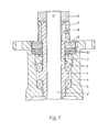
- a closure member At the lower end of the spindle 2, a closure member, not shown, is attached, which is pressed or lifted from the housing-side sealing surfaces during a translational movement of the spindle.
- the translatory movement is transmitted to the spindle 2 via a spindle nut 3.
- the spindle nut 3 and the valve spindle 2 are each provided with an interlocking trapezoidal thread.
- a shoulder 4 On the spindle nut 3, a shoulder 4 is formed laterally, via which the spindle nut 3 is mounted within the housing 1 in two spaced-apart axial ball bearings 5.
- a stroke limiting nut 6 is screwed onto the head of the spindle 2 and secured there.
- an electromotive actuator engages the spindle nut 3 via a transition bushing 7.
- the transition bushing 7 is connected to the spindle nut 3 via a feather key 8 in such a way that the transition bushing 7 can be displaced in the longitudinal direction of the spindle 2.
- an intermediate cover 9 is provided between the transition bushing 7 and the valve housing 1 or the neck 4 of the spindle nut 3, which surrounds the spindle nut 3 and the spindle 2 and which is also displaceable in the longitudinal direction of the spindle 2.
- this spring element Between the intermediate cover 9 and the housing 1 or the neck 4 of the spindle nut 3 is a spring element provided that surrounds the spindle nut 3. According to FIG. 1, this spring element consists of several superimposed disc springs 10.
- the transition bushing 7 and the intermediate cover 9 are displaced in the closing direction of the spindle 2.
- the plate springs 10 are loaded and the further rotating transition bush 7 rubs against the stroke-limiting nut 6 and the intermediate cover 9 until the frictional torque that is applied brakes the energy of the actuator introduced into the transition bush 7 and the actuator comes to a standstill.
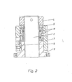
- the intermediate cover 9 is integrally formed on the transition bushing 7 and forms its upper limit.
- the transition bushing 7 and the intermediate cover 9 thus represent a one-piece piece.
- the spring element is inserted between the intermediate cover 9 and the upper end face of the spindle nut 3. It is limited on the inside by the spindle nut 3 and on the outside by the transition bushing 7.
- the spring element is formed by a plurality of resilient rings 11. These resilient rings 11 have conical end faces on which they touch. The resilient rings 11 are axially displaceable against one another, whereby they slide on the conical end walls in such a way that at least one resilient ring 11 is expanded in its diameter.
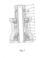
- the armature shown in FIG. 3 differs from that according to FIG. 1 or FIG. 2 in that a further, lower spring element 12 is provided below the shoulder 4 of the spindle nut 3.
- This lower spring element 12 is supported on the housing 1 and on the spindle nut 3.
- the same types of springs are used for the lower and the upper spring element, for example disc springs (FIG. 1) or resilient rings (FIG. 2).
- the spindle nut 3 is provided with a stop, for example a stop nut 13.
- the valve shown in FIG. 3 acts in the closing direction in the same way as the valve according to FIGS. 1 or 2.
- the lower spring element 12 also acts in the opening direction.
- the spindle 3 is pulled against a back seat in the sealing cover of the housing 1 to relieve the stuffing box.
- the damping device described also prevents an impermissibly high load on the transmission parts in this direction if the drive control fails.
- the spindle nut 3 is therefore pulled against the lower spring element 12.
- the transition bushing 7 and the intermediate cover 9 also the upper plate springs 10.
- a frictional torque arises between the transition bushing 7 and the intermediate cover 9.
- the spring forces and the frictional torque dampen the actuator torque.
- the valves described so far are to be used for a path-dependent shutdown of the actuator.
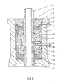
- the valve according to Fi g . 4 can be used for a torque-dependent shutdown.
- the damping applied system works depending on the spindle force, whereby the damping principle is the same in the opening and closing directions.
- the damping system comprises upper and lower annular spring elements 14, 15 which surround the spring elements formed by the plate springs 10, 12.
- the annular spring elements 14, 15 are formed by ring springs with conical end faces.
- a thrust ring 16 is connected, on the two sides of which non-resilient thrust bushings 17 are provided.
- the annular spring elements 14, 15 rest against these starting bushings 17. A distance s is maintained in each case from the thrust ring 16 and the intermediate cover 9.
- the upper and lower plate springs 10, 12 are designed so that the distance s in both directions does not fall below a safety distance due to the forces occurring during normal operation.
Landscapes
- Engineering & Computer Science (AREA)
- General Engineering & Computer Science (AREA)
- Mechanical Engineering (AREA)
- Electrically Driven Valve-Operating Means (AREA)
- Connection Of Motors, Electrical Generators, Mechanical Devices, And The Like (AREA)
- Transmission Devices (AREA)
- Mechanically-Actuated Valves (AREA)
Applications Claiming Priority (2)
| Application Number | Priority Date | Filing Date | Title |
|---|---|---|---|
| DE19833314781 DE3314781A1 (de) | 1983-04-23 | 1983-04-23 | Armatur |
| DE3314781 | 1983-04-23 |
Publications (3)
| Publication Number | Publication Date |
|---|---|
| EP0123021A2 true EP0123021A2 (fr) | 1984-10-31 |
| EP0123021A3 EP0123021A3 (en) | 1985-08-21 |
| EP0123021B1 EP0123021B1 (fr) | 1988-09-07 |
Family
ID=6197193
Family Applications (1)
| Application Number | Title | Priority Date | Filing Date |
|---|---|---|---|
| EP84100849A Expired EP0123021B1 (fr) | 1983-04-23 | 1984-01-27 | Garniture |
Country Status (5)
| Country | Link |
|---|---|
| US (1) | US4546281A (fr) |
| EP (1) | EP0123021B1 (fr) |
| CA (1) | CA1229079A (fr) |
| DE (2) | DE3314781A1 (fr) |
| SU (1) | SU1268113A3 (fr) |
Families Citing this family (6)
| Publication number | Priority date | Publication date | Assignee | Title |
|---|---|---|---|---|
| WO1989012194A1 (fr) * | 1988-06-10 | 1989-12-14 | Plotnikov Andrei D | Commande electrique |
| DE4013176A1 (de) * | 1990-04-25 | 1991-10-31 | Siemens Ag | Armatur zum absperren einer stroemung |
| DE4023636C2 (de) * | 1990-07-25 | 1994-07-14 | Siemens Ag | Armatur zum Absperren einer Strömung |
| DE19535051C1 (de) * | 1995-09-21 | 1996-11-28 | Honeywell Ag | Spindelmutter/Gewindespindel-Anordnung |
| DE10115636B4 (de) * | 2001-03-26 | 2004-10-14 | Mack & Schneider Gmbh | Umschaltventil in einem Fahrzeug |
| EP4411183B1 (fr) * | 2023-02-03 | 2026-04-01 | Georg Fischer Rohrleitungssysteme AG | Unité coulissante d'une vanne |
Family Cites Families (11)
| Publication number | Priority date | Publication date | Assignee | Title |
|---|---|---|---|---|
| US2212572A (en) * | 1937-08-25 | 1940-08-27 | Walworth Patents Inc | Valve |
| US3356874A (en) * | 1964-03-23 | 1967-12-05 | Royal Industries | Enclosed rotor drive device |
| US3616884A (en) * | 1969-09-11 | 1971-11-02 | Helmut Balz Gmbh Fa | Power-driven positioning system with interrupt means upon application of a predetermined positioning force at end points of travel, particulary for valves and the like |
| DE2242429C2 (de) * | 1969-09-11 | 1974-05-30 | Helmut Baelz Gmbh, 7100 Heilbronn | Motorischer Stellantrieb für Ventile oder dergleichen |
| US3704853A (en) * | 1971-03-26 | 1972-12-05 | Cons Controls Corp | Valve with differential clutching valve actuator |
| US3822612A (en) * | 1973-02-05 | 1974-07-09 | Worcester Controls Corp | Changeable speed and torque valve actuator |
| AT321655B (de) * | 1973-09-04 | 1975-04-10 | Schmidt Armaturen Gusswerk | Lagerungsanordnung für zur Umwandlung einer drehenden Bewegung in eine hin- und hergehende Bewegung dienender Mashinenteile |
| CH576672A5 (fr) * | 1974-04-03 | 1976-06-15 | Sulzer Ag | |
| US4111070A (en) * | 1977-04-04 | 1978-09-05 | Dresser Industries, Inc. | Valve actuator and spring biasing cartridge |
| EP0010113A1 (fr) * | 1978-10-23 | 1980-04-30 | BBC Aktiengesellschaft Brown, Boveri & Cie. | Limiteur de force axiale, notamment pour vanne |
| US4393319A (en) * | 1980-12-08 | 1983-07-12 | General Motors Corporation | Electric motor powered actuator |
-
1983
- 1983-04-23 DE DE19833314781 patent/DE3314781A1/de active Granted
-
1984
- 1984-01-27 EP EP84100849A patent/EP0123021B1/fr not_active Expired
- 1984-01-27 DE DE8484100849T patent/DE3473913D1/de not_active Expired
- 1984-03-15 US US06/589,739 patent/US4546281A/en not_active Expired - Fee Related
- 1984-03-16 SU SU843713083A patent/SU1268113A3/ru active
- 1984-04-18 CA CA000452300A patent/CA1229079A/fr not_active Expired
Also Published As
| Publication number | Publication date |
|---|---|
| US4546281A (en) | 1985-10-08 |
| EP0123021B1 (fr) | 1988-09-07 |
| CA1229079A (fr) | 1987-11-10 |
| SU1268113A3 (ru) | 1986-10-30 |
| DE3314781A1 (de) | 1984-10-25 |
| EP0123021A3 (en) | 1985-08-21 |
| DE3473913D1 (en) | 1988-10-13 |
| DE3314781C2 (fr) | 1987-05-27 |
Similar Documents
| Publication | Publication Date | Title |
|---|---|---|
| DE3211567C2 (fr) | ||
| DE2709325A1 (de) | Kupplung zur verbindung eines absperrorgans und einer absperrorgan-betaetigungsvorrichtung | |
| DE2629112C3 (de) | Schutzmechanismus zur verhinderung der uebertragung eines unzulaessigen drehmomentes, insbesondere ventil-schutzmechanismus fuer ventile | |
| EP0928388B1 (fr) | Clapet de turbine | |
| EP0115774A1 (fr) | Compresseur de ressorts | |
| DE3839317C2 (de) | Elektromotorischer Antrieb für ein Stellglied | |
| DD224381A5 (de) | Absperrschieber | |
| EP1064484B1 (fr) | Actionneur electromecanique pour une soupape, et turbine a vapeur | |
| EP3608557A1 (fr) | Vis d'entraînement à bille | |
| DE3417271A1 (de) | Elektromagnetisch ausrueckbare drehmomentuebertragungseinrichtung, insbesondere konusbremse | |
| DE3247490C2 (fr) | ||
| EP0123021A2 (fr) | Garniture | |
| EP1898122B1 (fr) | Dispositif de réglage destiné au réglage linéaire d'un actionneur | |
| DE2658988A1 (de) | Sicherheitsabsperrventil, insbesondere fuer gas-druckregelanlagen | |
| EP3106698A1 (fr) | Engrenage mécanique doté d'un arrêt du couple résistant | |
| DE2847956C2 (de) | Sicherheits-Absperrventil, insbesondere für Gas-Druckregelanlagen | |
| DD222949A5 (de) | Einstellbarer stoss- und schwingungsisolator fuer kardanisch aufgehaengte systeme mit grossen massen | |
| EP0462130B1 (fr) | Poste reducteur dote d'une fonction de securite dans un sens d'actionnement negatif | |
| DE3543593A1 (de) | Verzugsgetriebe und verfahren zur stossdaempfung | |
| EP4073398A1 (fr) | Dispositif de transmission de couple pour un dispositif d'entraînement d'un meuble, frein mécanique et accouplement d'arbres présentant un dispositif de transmission de couple de ce type | |
| EP1172591A2 (fr) | Dispositif de protection | |
| DE3342998C2 (de) | Kupplungsstück insbesondere für geteilte Armaturenspindeln | |
| EP0318459A2 (fr) | Commande de broche | |
| EP3130430A1 (fr) | Composant d'automatisation comprenant un frein sans courant | |
| EP3828128A1 (fr) | Dispositif de fermeture pour récipient avec un bouchon à vis |
Legal Events
| Date | Code | Title | Description |
|---|---|---|---|
| PUAI | Public reference made under article 153(3) epc to a published international application that has entered the european phase |
Free format text: ORIGINAL CODE: 0009012 |
|
| AK | Designated contracting states |
Designated state(s): CH DE FR GB IT LI NL |
|
| PUAL | Search report despatched |
Free format text: ORIGINAL CODE: 0009013 |
|
| AK | Designated contracting states |
Designated state(s): CH DE FR GB IT LI NL |
|
| 17P | Request for examination filed |
Effective date: 19850716 |
|
| 17Q | First examination report despatched |
Effective date: 19860922 |
|
| D17Q | First examination report despatched (deleted) | ||
| GRAA | (expected) grant |
Free format text: ORIGINAL CODE: 0009210 |
|
| AK | Designated contracting states |
Kind code of ref document: B1 Designated state(s): CH DE FR GB IT LI NL |
|
| GBT | Gb: translation of ep patent filed (gb section 77(6)(a)/1977) | ||
| REF | Corresponds to: |
Ref document number: 3473913 Country of ref document: DE Date of ref document: 19881013 |
|
| ET | Fr: translation filed | ||
| ITF | It: translation for a ep patent filed | ||
| PGFP | Annual fee paid to national office [announced via postgrant information from national office to epo] |
Ref country code: NL Payment date: 19890131 Year of fee payment: 9 |
|
| PLBE | No opposition filed within time limit |
Free format text: ORIGINAL CODE: 0009261 |
|
| STAA | Information on the status of an ep patent application or granted ep patent |
Free format text: STATUS: NO OPPOSITION FILED WITHIN TIME LIMIT |
|
| 26N | No opposition filed | ||
| PGFP | Annual fee paid to national office [announced via postgrant information from national office to epo] |
Ref country code: CH Payment date: 19910111 Year of fee payment: 8 |
|
| PG25 | Lapsed in a contracting state [announced via postgrant information from national office to epo] |
Ref country code: LI Effective date: 19920131 Ref country code: CH Effective date: 19920131 |
|
| PG25 | Lapsed in a contracting state [announced via postgrant information from national office to epo] |
Ref country code: NL Effective date: 19920801 |
|
| NLV4 | Nl: lapsed or anulled due to non-payment of the annual fee | ||
| REG | Reference to a national code |
Ref country code: CH Ref legal event code: PL |
|
| PGFP | Annual fee paid to national office [announced via postgrant information from national office to epo] |
Ref country code: GB Payment date: 19931214 Year of fee payment: 11 |
|
| PGFP | Annual fee paid to national office [announced via postgrant information from national office to epo] |
Ref country code: FR Payment date: 19931221 Year of fee payment: 11 |
|
| PGFP | Annual fee paid to national office [announced via postgrant information from national office to epo] |
Ref country code: DE Payment date: 19931222 Year of fee payment: 11 |
|
| PG25 | Lapsed in a contracting state [announced via postgrant information from national office to epo] |
Ref country code: GB Effective date: 19950127 |
|
| GBPC | Gb: european patent ceased through non-payment of renewal fee |
Effective date: 19950127 |
|
| PG25 | Lapsed in a contracting state [announced via postgrant information from national office to epo] |
Ref country code: FR Effective date: 19950929 |
|
| PG25 | Lapsed in a contracting state [announced via postgrant information from national office to epo] |
Ref country code: DE Effective date: 19951003 |
|
| REG | Reference to a national code |
Ref country code: FR Ref legal event code: ST |