EP0123033A1 - Dispositif de maintien pour pièces de fonderie dans des ateliers d'ébarbage - Google Patents
Dispositif de maintien pour pièces de fonderie dans des ateliers d'ébarbage Download PDFInfo
- Publication number
- EP0123033A1 EP0123033A1 EP84101448A EP84101448A EP0123033A1 EP 0123033 A1 EP0123033 A1 EP 0123033A1 EP 84101448 A EP84101448 A EP 84101448A EP 84101448 A EP84101448 A EP 84101448A EP 0123033 A1 EP0123033 A1 EP 0123033A1
- Authority
- EP
- European Patent Office
- Prior art keywords
- casting
- supports
- gripper part
- axis
- rotation
- Prior art date
- Legal status (The legal status is an assumption and is not a legal conclusion. Google has not performed a legal analysis and makes no representation as to the accuracy of the status listed.)
- Granted
Links
- 238000005266 casting Methods 0.000 title claims abstract description 86
- 238000004140 cleaning Methods 0.000 title claims abstract description 20
- 238000005422 blasting Methods 0.000 claims description 13
- 238000005520 cutting process Methods 0.000 claims description 2
- 239000003110 molding sand Substances 0.000 description 5
- 239000003795 chemical substances by application Substances 0.000 description 3
- XEEYBQQBJWHFJM-UHFFFAOYSA-N Iron Chemical compound [Fe] XEEYBQQBJWHFJM-UHFFFAOYSA-N 0.000 description 2
- 230000006735 deficit Effects 0.000 description 1
- 229910052742 iron Inorganic materials 0.000 description 1
- 238000000034 method Methods 0.000 description 1
- 239000011505 plaster Substances 0.000 description 1
- 230000000717 retained effect Effects 0.000 description 1
- 239000004576 sand Substances 0.000 description 1
- 238000007873 sieving Methods 0.000 description 1
Images


Classifications
-
- B—PERFORMING OPERATIONS; TRANSPORTING
- B24—GRINDING; POLISHING
- B24C—ABRASIVE OR RELATED BLASTING WITH PARTICULATE MATERIAL
- B24C3/00—Abrasive blasting machines or devices; Plants
- B24C3/08—Abrasive blasting machines or devices; Plants essentially adapted for abrasive blasting of travelling stock or travelling workpieces
- B24C3/083—Transfer or feeding devices; Accessories therefor
-
- Y—GENERAL TAGGING OF NEW TECHNOLOGICAL DEVELOPMENTS; GENERAL TAGGING OF CROSS-SECTIONAL TECHNOLOGIES SPANNING OVER SEVERAL SECTIONS OF THE IPC; TECHNICAL SUBJECTS COVERED BY FORMER USPC CROSS-REFERENCE ART COLLECTIONS [XRACs] AND DIGESTS
- Y10—TECHNICAL SUBJECTS COVERED BY FORMER USPC
- Y10S—TECHNICAL SUBJECTS COVERED BY FORMER USPC CROSS-REFERENCE ART COLLECTIONS [XRACs] AND DIGESTS
- Y10S294/00—Handling: hand and hoist-line implements
- Y10S294/902—Gripping element
Definitions
- the invention relates to a conveying device for castings in casting plastering systems with at least one pincer-like casting holder rotating around a horizontal or slightly inclined axis with two gripper parts, of which the lower one serves to support at least one casting, the upper one serves as a clamping member for clamping the same.
- Conveyors with such tong-like casting holders are known (for example DE-PS 25 10 827, DE-OS 26 13 717). They are used primarily for cleaning individual large castings, such as engine blocks or the like, which have a large number of recesses, cavities, niches, etc. and consequently from all sides and among several Angles need to be blasted to effectively loosen and remove the remaining sand. Such castings are therefore not only moved in a single direction of movement by a casting cleaning system, but are also intensively exposed to the cleaning jets by rotating the casting holder. At the same time, the rotary movement ensures that loosened molding sand can fall off and unprocessed areas can be exposed to the cleaning jet. This also ensures that blasting media cannot deposit in niches, cavities, etc.
- the invention has for its object to further develop a conveyor of the structure described above in such a way that castings with deep cavities and complex shapes can be blasted effectively and in a reasonably short time without manual reworking is required.
- the object of the invention is achieved in that the lower gripper part has two or more supports for at least one casting and accommodate the supports of the casting in an angular position to the axis of rotation.
- the castings While in the known devices, the castings are oriented in the direction of one of their axes, mostly the longitudinal axis and in this position are gripped by the tong-like casting holder, in the embodiment according to the invention they are received in an inclined position with respect to the axis of rotation, so that they rotate when the tong-like casting holder rotates Carry out a kind of wobble movement and consequently be exposed to the cleaning jet at constantly changing angles.
- the supports can be punctiform, linear or preferably strip-shaped.
- the inclined position has the further advantage that two larger castings can be accommodated at the same time by a casting holder by arranging them with their longitudinal axes in a parallel inclined position.
- the lower gripper part has at least two further, preferably strip-shaped supports, which are arranged at the same angle and at approximately the same distance from one another as the two first, preferably also strip-shaped supports on both sides of the axis of rotation, however are offset from the free end of the gripper part.
- the castings are thus taken up in a position parallel to one another and in the same inclined position to the axis of rotation.
- the aforesaid embodiment gives the possibility that the one support of the first pair of supports arranged on one side of the axis of rotation is integral with the one of the other pair of supports arranged on the other side of the axis of rotation. This makes the design of the supports and the lower gripper part particularly simple.
- the upper gripper part has at least one pendulum-suspended beam, via which the clamping force is transmitted to the casting in the clamping position of the casting holder.
- the bar preferably runs at an angle with respect to the axis of rotation, which corresponds approximately to the angle of attack of the supports on the lower gripper part with respect to the axis of rotation. Furthermore, the bar is advantageously arranged between two supports.
- each pair of supports on the lower gripper part is advantageously assigned a pendulum-suspended beam on the upper gripper part, so that the aforementioned advantages are retained for each cast part.
- this embodiment is preferably modified in such a way that the two beams are suspended in an oscillating manner at the ends of a common beam, which in turn is suspended in an oscillating manner on the upper part of the gripper. This ensures, for example during a pivoting movement of the upper gripper part, that both castings are securely gripped regardless of its angular position in the clamping position. Differences in height between the two castings can also be compensated for by this design without any impairment of the clamping force.
- the supports and / or the beams are comb-like on their sides adjacent to the casting, the tines thus formed advantageously ending in blunt cutting edges.
- the area of the casting covered by the supports with respect to the cleaning jet is limited to the smallest possible extent, so that the cleaning jet hits the casting on its entire outer surface almost unhindered. Furthermore, this training ensures that loosened molding sand and used abrasive can fall off unhindered.
- the vibrating device has a roller block or a sliding surface and the tong-like casting holder have a tread, by means of which it rolls on the roller block or the sliding surface during the rotational movement.
- the tread can, for example, be designed as a rotationally symmetrical race for the rotational movement of the tongs-like casting holder, which surrounds the gripper parts of the casting holder at a distance and is supported on the supporting structure of the casting holder via struts.
- the race can also be attached to the lower gripper part via struts.
- the diameter of the race must - depending on the location of its attachment - be dimensioned so that it leaves enough space for the opening width of the pincer-type casting holder there.
- the lower gripper part which is generally fixed, and the struts of the race are fastened to a common support plate, which are connected to the support structure of the tong holder with the interposition of vibration dampers.
- the same purpose serves the further measure that the self-aligning bearings of the beams or of the common beam with respect to the upper gripper part, which generally performs the opening movement of the pincer-like casting holder, are vibration-damped.
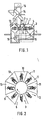
- each casting holder has a tensioning drive 6 for the upper gripper part 5, which is located within the carousel, and a rotary drive 7, by means of which the tong-like casting holder is driven in rotation around a horizontal axis.
- the cleaning booth 1 has several chambers or stations which can be seen in more detail in FIG. 2.
- the first station 8 is designed as a loading station, where the castings to be cleaned are fed and inserted into a tongs holder which is in the ready position.
- the next station 9 serves, for example, as a lock and shields the following beam stations 10 from the surroundings.
- the last blasting station 10 is followed, in succession, by two stations 11, in which the blasting medium which is still in the casting and, above all, is deposited in cavities is emptied.
- the last station is 11 again designed as a lock. This then follows - lying next to the loading station 8 - a station 12 for unloading the castings.
- centrifugal wheels 13 are arranged in the ceiling of the cleaning booth, to which the blasting medium is fed via a distributor 14.
- the used blasting agent leaves the cleaning booth 1 on its underside and reaches the distributor 14 again via an elevator 16 via conveyors 15 and sieving devices which separate the molding sand from the blasting agent.
- vibrating devices can optionally be arranged, which are provided with a roller block, on which the rotating, pincer-like casting holder 3 lie and roll during their rotational movement.
- each casting holder has a lower, fixed gripper part 4 and an upper gripper part I 5, which carries out the clamping movement. They sit on a housing-like support structure 17, which is driven by a shaft 18 guided through the wall of the cleaning booth 1.
- a labyrinth seal 19 is arranged on the passage of the shaft 18 through the wall of the cleaning booth 1, which prevents the passage of blasting media.
- a drive (not shown in detail) for actuating the upper gripper part 5 is guided through the hollow drive shaft 18.
- the upper gripper part 5 essentially has two adjacent bars 20 (FIG.
- the upper gripping part 5 can thus move up or down by a certain angle from the horizontal position shown in FIG.
- the upper gripper part I 5 then executes its clamping movement against the casting.
- the upper gripper part 5 has two clamping beams 22 arranged one behind the other, which are suspended in pendulums 24 on brackets 23.
- the tabs 23 are in turn attached to an arm 25 of a beam, which in turn is suspended on the crosspiece 21 of the upper gripper part 5 in an oscillating manner.
- the bearing 26 of this common beam 25 is, as schematically shown in FIG. 4, equipped with a vibration damper.
- the two bars 22 have a comb-like, possibly stepped profile on their side facing the lower gripper part. While the axes of the bearings 24 of the clamping beam 22 are arranged obliquely to the axis of rotation of the casting holder, the bearing axis of the common beam 25 runs perpendicular to the latter.
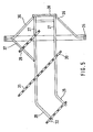
- the lower fixed gripper part 4 consists of two upright flat iron 27, which run parallel to one another and are initially arranged at the same distance on both sides of the axis of rotation of the casting holder. At their front end 28, the strips are angled to one side, but still parallel to each other.
- Two rear supports 29, 30 are attached to the upright strips 27 at an angle to the axis of rotation. At a distance from it and at the same angular position with respect to the axis of rotation, two further supports 31, 32 are arranged at a distance from one another in the front region of the lower gripper part 4. The arrangement is such that one support 30 of the rear pair of supports is integral with the support 31 of the other pair of supports arranged on the opposite side of the axis of rotation.
- the supports 29, 30, 31 and 32 are, as shown in particular in FIG. 3, comb-like, the upstanding tines 33 ending in blunt blades 34.
- the individual beams 22 arranged on the upper gripper part 5 are each arranged between the supports 29, 30 and 31, 32 on the lower gripper part and, as shown in FIG. 4, run at the same angle with respect to the axis of rotation of the pliers-like casting holder.
- the pincer-like cast piece holder has a tread which lies against the rolls and by means of which it rolls on the rolls during the rotational movement of the cast piece holder.
- the tread is formed by a circular race 35, which is supported by struts 36 on the housing 17 or by struts 37 on the lower gripper part.
- the diameter of the race 35 is dimensioned so that the gripper parts can carry out their opening movement unhindered.
- the struts 36 in this embodiment like the upright strips 27 of the lower gripper part 4, are fastened to a support plate 38, which in turn is connected to the housing 17 via vibration dampers 39.
Landscapes
- Engineering & Computer Science (AREA)
- Mechanical Engineering (AREA)
- Load-Engaging Elements For Cranes (AREA)
- Cleaning In General (AREA)
Applications Claiming Priority (2)
| Application Number | Priority Date | Filing Date | Title |
|---|---|---|---|
| DE19833306857 DE3306857A1 (de) | 1983-02-26 | 1983-02-26 | Foerdereinrichtung fuer gussstuecke in gussputzanlagen |
| DE3306857 | 1983-02-26 |
Publications (2)
| Publication Number | Publication Date |
|---|---|
| EP0123033A1 true EP0123033A1 (fr) | 1984-10-31 |
| EP0123033B1 EP0123033B1 (fr) | 1988-03-02 |
Family
ID=6191959
Family Applications (1)
| Application Number | Title | Priority Date | Filing Date |
|---|---|---|---|
| EP84101448A Expired EP0123033B1 (fr) | 1983-02-26 | 1984-02-13 | Dispositif de maintien pour pièces de fonderie dans des ateliers d'ébarbage |
Country Status (3)
| Country | Link |
|---|---|
| US (1) | US4688586A (fr) |
| EP (1) | EP0123033B1 (fr) |
| DE (1) | DE3306857A1 (fr) |
Cited By (1)
| Publication number | Priority date | Publication date | Assignee | Title |
|---|---|---|---|---|
| CN103878701A (zh) * | 2014-03-27 | 2014-06-25 | 辽宁澳深低温装备股份公司 | 一种抛丸机 |
Families Citing this family (7)
| Publication number | Priority date | Publication date | Assignee | Title |
|---|---|---|---|---|
| DE4017677A1 (de) * | 1990-06-01 | 1991-12-05 | Schlick Roto Jet Masch | Zusatzvorrichtung fuer eine schleuderstrahlanlage zur entfernung des strahlmittels bei grossen werkstuecken |
| US5609171A (en) * | 1996-02-13 | 1997-03-11 | Kuo; Fu-Chin | Lipstick molding mold cleaning apparatus |
| US6526999B2 (en) * | 2001-04-30 | 2003-03-04 | Joseph J. Tebbe | Random high pressure water jetting nozzle for cleaning castings |
| GB2514736A (en) | 2012-03-11 | 2014-12-03 | Airway Medix Sp Lka Z O O | Oral care system method and kit |
| FR3078276B1 (fr) * | 2018-02-23 | 2026-01-16 | Safran Aircraft Engines | Outillage de decochage d'une grappe de pieces de fonderie a cire perdue |
| CN113547104A (zh) * | 2020-04-24 | 2021-10-26 | 邓超 | 一种复杂内腔铸件的振动除芯装置 |
| CN114260234B (zh) * | 2021-12-17 | 2022-12-27 | 新昌县海博科技股份有限公司 | 一种转笼式清洗机及其清洗方法 |
Citations (5)
| Publication number | Priority date | Publication date | Assignee | Title |
|---|---|---|---|---|
| US1453045A (en) * | 1922-02-13 | 1923-04-24 | Vorm Adolf Finze & Co Ag | Chuck jaw |
| DE2510827C2 (de) * | 1975-03-12 | 1977-02-24 | Badische Maschf Gmbh | Foerdereinrichtung fuer zylinderbloecke oder aehnliche werkstuecke durch eine schleuderstrahlanlage |
| DE2613717A1 (de) * | 1976-03-31 | 1977-10-06 | Berger Maschf Gmbh | Schleuderstrahlvorrichtung zum allseitigen reinigen von vielflaechigen werkstuecken |
| DE3010964A1 (de) * | 1979-04-04 | 1980-11-06 | Fischer Ag Georg | Verfahren und vorrichtung zum entleeren von hohlraeume aufweisenden werkstuecken |
| EP0082283A1 (fr) * | 1981-11-14 | 1983-06-29 | BMD Badische Maschinenfabrik Durlach GmbH | Moyen de transport pour pièces coulées |
Family Cites Families (18)
| Publication number | Priority date | Publication date | Assignee | Title |
|---|---|---|---|---|
| DE296674C (fr) * | ||||
| DE233219C (fr) * | ||||
| US837559A (en) * | 1905-11-06 | 1906-12-04 | Lozelle F Graham | Fruit-washing machine. |
| US1494436A (en) * | 1921-09-12 | 1924-05-20 | Willard Storage Battery Co | Clamp for use in coating battery boxes and the like |
| US1578816A (en) * | 1925-07-17 | 1926-03-30 | Eifried Petar | Combined pot and lid lifter |
| US2078848A (en) * | 1936-03-21 | 1937-04-27 | Greger Joseph | Clamp |
| US2319501A (en) * | 1940-08-02 | 1943-05-18 | Jenkins Bros | Testing equipment |
| US2780229A (en) * | 1953-02-16 | 1957-02-05 | Udylite Corp | Work-handling apparatus for treating hollow articles |
| US2926675A (en) * | 1956-04-18 | 1960-03-01 | Ajem Lab Inc | Cradle apparatus for power washing equipment |
| US2991791A (en) * | 1957-06-21 | 1961-07-11 | Procedes Rovac | Automatic apparatus for electrolytic processing and the like |
| US3382844A (en) * | 1964-07-01 | 1968-05-14 | Lasalco Inc | Work treating apparatus |
| US3391678A (en) * | 1967-04-03 | 1968-07-09 | Philip G. Luckhardt | Motive power system |
| US3370879A (en) * | 1967-05-25 | 1968-02-27 | Textron Inc | Connecting means for fruit harvester |
| US3885825A (en) * | 1971-12-20 | 1975-05-27 | Owens Illinois Inc | Article handling chuck |
| US3967946A (en) * | 1972-12-15 | 1976-07-06 | Emhart Corporation | Mold holder arms for glassware forming machine and method of operating the same |
| DE2444172C2 (de) * | 1974-09-16 | 1983-01-20 | Otto Dürr Anlagenbau GmbH, 7000 Stuttgart | Anlage zur Oberflächenbehandlung von Werkstücken |
| US4448405A (en) * | 1981-07-06 | 1984-05-15 | General Electric Company | Versatile gripping device |
| US4456293A (en) * | 1982-08-24 | 1984-06-26 | International Business Machines Corporation | Article gripping apparatus |
-
1983
- 1983-02-26 DE DE19833306857 patent/DE3306857A1/de active Granted
-
1984
- 1984-02-13 EP EP84101448A patent/EP0123033B1/fr not_active Expired
- 1984-02-24 US US06/583,435 patent/US4688586A/en not_active Expired - Lifetime
Patent Citations (5)
| Publication number | Priority date | Publication date | Assignee | Title |
|---|---|---|---|---|
| US1453045A (en) * | 1922-02-13 | 1923-04-24 | Vorm Adolf Finze & Co Ag | Chuck jaw |
| DE2510827C2 (de) * | 1975-03-12 | 1977-02-24 | Badische Maschf Gmbh | Foerdereinrichtung fuer zylinderbloecke oder aehnliche werkstuecke durch eine schleuderstrahlanlage |
| DE2613717A1 (de) * | 1976-03-31 | 1977-10-06 | Berger Maschf Gmbh | Schleuderstrahlvorrichtung zum allseitigen reinigen von vielflaechigen werkstuecken |
| DE3010964A1 (de) * | 1979-04-04 | 1980-11-06 | Fischer Ag Georg | Verfahren und vorrichtung zum entleeren von hohlraeume aufweisenden werkstuecken |
| EP0082283A1 (fr) * | 1981-11-14 | 1983-06-29 | BMD Badische Maschinenfabrik Durlach GmbH | Moyen de transport pour pièces coulées |
Cited By (1)
| Publication number | Priority date | Publication date | Assignee | Title |
|---|---|---|---|---|
| CN103878701A (zh) * | 2014-03-27 | 2014-06-25 | 辽宁澳深低温装备股份公司 | 一种抛丸机 |
Also Published As
| Publication number | Publication date |
|---|---|
| EP0123033B1 (fr) | 1988-03-02 |
| DE3306857A1 (de) | 1984-08-30 |
| DE3306857C2 (fr) | 1990-11-22 |
| US4688586A (en) | 1987-08-25 |
Similar Documents
| Publication | Publication Date | Title |
|---|---|---|
| DE2902197C2 (fr) | ||
| DE202007018558U1 (de) | Rüttelvorrichtung zum Entfernen des Kernsandes aus hohlen Gussstücken | |
| EP0123033B1 (fr) | Dispositif de maintien pour pièces de fonderie dans des ateliers d'ébarbage | |
| DE2140235B2 (de) | Anordnung zum Waschen von Fahrzeugen | |
| DE1696109C2 (de) | Vorrichtung zum Reinigen und Behandeln von Werkstücken | |
| EP1292517A1 (fr) | Dispositif de prelevement automatique d'objets situes dans des conteneurs | |
| CH657085A5 (de) | Mehrstationenstrahlbearbeitungsmaschine. | |
| DE69806485T2 (de) | Schleuderstrahlmaschine zur reinigung eines linearmetallelements | |
| DE8305502U1 (de) | Fördereinrichtung für Gußstücke in Gußputzanlagen | |
| EP0005144A2 (fr) | Machine de nettoyage pour pièces coulées et autres pièces | |
| WO1984004709A1 (fr) | Installation pour nettoyer et pour proteger la surface superieure de la face interieure d'un reservoir de forme cylindrique muni d'un couvercle rigidement fixe | |
| DE816674C (de) | Vorrichtung zum maschinellen Putzen von gebrauchten Mauersteinen | |
| DE3306856C2 (fr) | ||
| DE1757702C3 (de) | Vorrichtung zum Reinigen von fortlaufend bewegten Flaschenkasten | |
| DE1546072B1 (de) | Vorrichtung zum Reinigenvon Bohrungen aufweisenden Werkstuecken | |
| DE385534C (de) | Maschine zum Enthaaren und Reinigen von Tierkoerpern | |
| DE2716070C3 (de) | Vorrichtung zum Räumen von abgelagertem Strahlmittel | |
| DE1141916B (de) | Einrichtung zur Oberflaechenbehandlung, z. B. zum Entzundern von Walzdraht in einer Strahlkammer | |
| DE2645292C2 (de) | Slinger zum Auskleiden von Industrieöfen mit feuerfester Masse | |
| DE2714101C2 (de) | Vorrichtung zum Abtrennen der passierfähigen Teile des Grätengerüstes filetierter Fische | |
| EP1098580A1 (fr) | Procedes et dispositifs pour nettoyer des surfaces | |
| EP1163977A2 (fr) | Procédé et appareil pour laver les couteaux du dispositif pour couper des bandes longitudinalement | |
| AT368470B (de) | Vorrichtung zur entnahme von futter aus einem flachsilo | |
| DE412430C (de) | Verfahren und Vorrichtung zur Behandlung von koernigem Gut, besonders von Formsand | |
| DE2055216A1 (de) | Maschine zum Schneiden bzw. Sägen von Steinblocken, insbesondere von Marmerblöcken. |
Legal Events
| Date | Code | Title | Description |
|---|---|---|---|
| PUAI | Public reference made under article 153(3) epc to a published international application that has entered the european phase |
Free format text: ORIGINAL CODE: 0009012 |
|
| 17P | Request for examination filed |
Effective date: 19840828 |
|
| AK | Designated contracting states |
Designated state(s): FR GB IT SE |
|
| GRAA | (expected) grant |
Free format text: ORIGINAL CODE: 0009210 |
|
| AK | Designated contracting states |
Kind code of ref document: B1 Designated state(s): FR GB IT SE |
|
| ET | Fr: translation filed | ||
| GBT | Gb: translation of ep patent filed (gb section 77(6)(a)/1977) | ||
| ITF | It: translation for a ep patent filed | ||
| PLBE | No opposition filed within time limit |
Free format text: ORIGINAL CODE: 0009261 |
|
| STAA | Information on the status of an ep patent application or granted ep patent |
Free format text: STATUS: NO OPPOSITION FILED WITHIN TIME LIMIT |
|
| 26N | No opposition filed | ||
| ITTA | It: last paid annual fee | ||
| EAL | Se: european patent in force in sweden |
Ref document number: 84101448.3 |
|
| REG | Reference to a national code |
Ref country code: GB Ref legal event code: IF02 |
|
| PGFP | Annual fee paid to national office [announced via postgrant information from national office to epo] |
Ref country code: GB Payment date: 20020130 Year of fee payment: 19 |
|
| PGFP | Annual fee paid to national office [announced via postgrant information from national office to epo] |
Ref country code: SE Payment date: 20020215 Year of fee payment: 19 |
|
| PGFP | Annual fee paid to national office [announced via postgrant information from national office to epo] |
Ref country code: FR Payment date: 20020221 Year of fee payment: 19 |
|
| PG25 | Lapsed in a contracting state [announced via postgrant information from national office to epo] |
Ref country code: GB Free format text: LAPSE BECAUSE OF NON-PAYMENT OF DUE FEES Effective date: 20030213 |
|
| PG25 | Lapsed in a contracting state [announced via postgrant information from national office to epo] |
Ref country code: SE Free format text: LAPSE BECAUSE OF NON-PAYMENT OF DUE FEES Effective date: 20030214 |
|
| EUG | Se: european patent has lapsed | ||
| GBPC | Gb: european patent ceased through non-payment of renewal fee | ||
| PG25 | Lapsed in a contracting state [announced via postgrant information from national office to epo] |
Ref country code: FR Free format text: LAPSE BECAUSE OF NON-PAYMENT OF DUE FEES Effective date: 20031031 |
|
| REG | Reference to a national code |
Ref country code: FR Ref legal event code: ST |