EP0123076A1 - Einrichtung zum Zertrennen eines Rohres aus einem in einem Rohrboden endenden Bündel - Google Patents
Einrichtung zum Zertrennen eines Rohres aus einem in einem Rohrboden endenden Bündel Download PDFInfo
- Publication number
- EP0123076A1 EP0123076A1 EP84102396A EP84102396A EP0123076A1 EP 0123076 A1 EP0123076 A1 EP 0123076A1 EP 84102396 A EP84102396 A EP 84102396A EP 84102396 A EP84102396 A EP 84102396A EP 0123076 A1 EP0123076 A1 EP 0123076A1
- Authority
- EP
- European Patent Office
- Prior art keywords
- tube
- plate
- hollow shaft
- sheet
- tube sheet
- Prior art date
- Legal status (The legal status is an assumption and is not a legal conclusion. Google has not performed a legal analysis and makes no representation as to the accuracy of the status listed.)
- Granted
Links
- 230000008439 repair process Effects 0.000 abstract description 5
- 238000000926 separation method Methods 0.000 description 5
- 230000035515 penetration Effects 0.000 description 4
- 230000007797 corrosion Effects 0.000 description 2
- 238000005260 corrosion Methods 0.000 description 2
- 230000008719 thickening Effects 0.000 description 2
- XLYOFNOQVPJJNP-UHFFFAOYSA-N water Substances O XLYOFNOQVPJJNP-UHFFFAOYSA-N 0.000 description 2
- 238000004140 cleaning Methods 0.000 description 1
- 230000000694 effects Effects 0.000 description 1
- 230000002349 favourable effect Effects 0.000 description 1
- 238000010438 heat treatment Methods 0.000 description 1
- 238000007689 inspection Methods 0.000 description 1
- 239000000463 material Substances 0.000 description 1
- 238000005192 partition Methods 0.000 description 1
- NQLVQOSNDJXLKG-UHFFFAOYSA-N prosulfocarb Chemical compound CCCN(CCC)C(=O)SCC1=CC=CC=C1 NQLVQOSNDJXLKG-UHFFFAOYSA-N 0.000 description 1
Images

Classifications
-
- B—PERFORMING OPERATIONS; TRANSPORTING
- B23—MACHINE TOOLS; METAL-WORKING NOT OTHERWISE PROVIDED FOR
- B23D—PLANING; SLOTTING; SHEARING; BROACHING; SAWING; FILING; SCRAPING; LIKE OPERATIONS FOR WORKING METAL BY REMOVING MATERIAL, NOT OTHERWISE PROVIDED FOR
- B23D21/00—Machines or devices for shearing or cutting tubes
- B23D21/14—Machines or devices for shearing or cutting tubes cutting inside the tube
-
- F—MECHANICAL ENGINEERING; LIGHTING; HEATING; WEAPONS; BLASTING
- F22—STEAM GENERATION
- F22B—METHODS OF STEAM GENERATION; STEAM BOILERS
- F22B37/00—Component parts or details of steam boilers
- F22B37/002—Component parts or details of steam boilers specially adapted for nuclear steam generators, e.g. maintenance, repairing or inspecting equipment not otherwise provided for
- F22B37/003—Maintenance, repairing or inspecting equipment positioned in or via the headers
Definitions
- the invention relates to a device for cutting a tube from a bundle of parallel straight tubes ending in a tube sheet.
- an inspection and repair device for steam generators which allows various measuring and repair devices as well as tools to be led into the pipes of the steam generator of a pressurized water reactor.
- the tools are only moved in the longitudinal direction of the pipes.
- the object of the invention is to enable the separation of a pipe with a cutting movement transverse to the pipe axis, so that a suitable separation point is created, for example, for repairs to the pipe.
- the separation point should be at a certain distance from the tube sheet and result in defined edges at the tube end, which is well suited for subsequent cleaning and reconnection with repair tubes.
- the device according to the invention is designed such that a hollow shaft with an axis parallel to the tubes is rotatably mounted in a plate that can be connected to the tube sheet, that the hollow shaft has an eccentric bore, that a tube with an eccentric bore is in the bore cylindrical interior is mounted that a drive shaft is mounted in the interior, which at the end of the tube facing the tube sheet outside the same holds a cutting tool and is provided at the side remote from the tube bottom end of the tube with a drive, and that the hollow shaft and the tube are positively connected together so that they from the side remote from the tube bottom side of the plate are rotated against one another by 180 0 .
- the double eccentric bearing of the drive shaft of the cutting tool ensures a defined and stepless adjustment of the cutting depth. This allows the cutting effect to be optimally adapted to the material and wall thickness of the pipes to be cut.
- the distance from the tube sheet results from the easily adjustable depth of penetration of the hollow shaft into the plate located on the tube sheet. At the same time, this ensures that the adjustment options and the cutting movement can also be attached and operated by remote control.
- the new device defined above therefore meets the above-mentioned requirements in the most favorable manner.
- the hollow shaft and the tube can be coupled to one another via a gear pair with a pinion which is several times smaller than the associated counter gear.
- the hollow shaft can advantageously have a flange on the side of the plate facing away from the tube sheet, on which a motor attached to the plate acts to rotate the hollow shaft.
- clamp connection can be stepless set the depth of penetration of the hollow shaft into the pipe and thus the distance of the pipe's separation point from the pipe bottom.
- the plate of the new device can be attached to the tube sheet in different ways. It preferably has, on the side facing away from the tube sheet, remote-controlled fastening means for attachment to the tube sheet, for example expanding mandrels known per se which engage in tube ends of the bundle or other openings in the tube sheet.
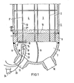
- FIG. 1 shows in a vertical section the lower part of a steam generator for a pressurized water reactor
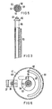
- FIG. 2 shows in a larger vertical section the new device in one position of the eccentric
- FIG. 3 shows a section of the device in another position
- 4 and 5 two associated cross sections are drawn
- FIG. 6 shows another part of the device facing away from the tube sheet in another cross section.
- the steam generator to be processed is designated as a whole by 1. It is a U-tube steam generator, the bundle of parallel tubes 2 forms two legs 3 and 4, which end in the tube sheet 5 so that one leg 3 of one half 6 of a primary chamber delimited by the bottom 7 and the other leg 4 is assigned to the other part n 8 of the primary chamber.
- the two halves 6, 8 are delimited from one another by a partition 9 and are accessible via pipe sockets 10 and 11 serving as manholes.
- the tubes 2 consist of Incaloy 800 and have an outer diameter of 22 mm and a wall thickness of 1.2 mm.
- the heating tube 2 ' is to be cut by a cut at the separation point 12 in order to be able to replace the lower part 2' 'in FIG. 1 which is caused by corrosion in the tube sheet 5 adjacent layer 13, which is particularly at risk from corrosion.
- the device according to the invention designated as a whole by 14, is introduced into the chamber 8.
- the device 14 comprises, as can be seen in FIG. 1, a mounting plate 16 which is attached to the tube sheet 5 by means of fastening means 17 indicated by dashed lines.
- the fastening means are, for example, expanding mandrels which engage in the bores of the tube sheet 5 which accommodate the tubes 2.
- a first drive motor 18, which is fed via a supply line 19, and a second drive motor 20 with a supply line 21 are seated on the plate 16.
- a control line 23 leads to a control panel 24 located next to the steam generator.
- a sleeve 27 is mounted in the mounting plate 16 with a ball bearing 26.
- the ball bearing 26 is fixed with a motor holding plate 28 to which the drive motor 18 is flanged.
- the motor 18 carries on its shaft 30 a pinion 31 which engages in a toothed ring 32 lying in a horizontal plane on the outer edge of a flange body 33.
- a clamp 35 is connected to the flange body, which has a screw connection 36 is to be closed or released.
- a bracket 37 is screwed, which carries the drive motor 38 for a pinion 39.
- the pinion 39 meshes with a toothing 40 on the circumference of a swivel plate 41, so that an adjustment between the swivel plate 40 and the clamp 35 can be effected.
- a hollow shaft 44 is fixed in the sleeve 27 with the clamp 35, which comprises a cylindrical tube 45 with end pieces 46 at the upper end and 47 at the lower end.
- the end pieces 46 and 47 have an eccentric bore 48, as can be seen in FIGS. 3 to 6.
- a tube 50 is rotatably mounted, which is also eccentric because its interior 51 is eccentric to the bore 48 by 1.25 mm.
- a drive shaft 53 is rotatably mounted, which is assigned to the drive motor 20 visible in FIG. 1.
- the bearing of the drive shaft comprises a lower, ball bearing thrust bearing 54, which is fastened with an adjusting ring 55, and an upper ball bearing 56, on which sits the collar of a thickening 58, which protrudes from the end piece 46.
- An interchangeable prism cutter 60 sits on the thickening 58 and is fastened, for example, with a nut 61.
Landscapes
- Engineering & Computer Science (AREA)
- Physics & Mathematics (AREA)
- Mechanical Engineering (AREA)
- High Energy & Nuclear Physics (AREA)
- Thermal Sciences (AREA)
- General Engineering & Computer Science (AREA)
- Monitoring And Testing Of Nuclear Reactors (AREA)
Abstract
Description
- Die Erfindung betrifft eine Einrichtung zum Zertrennen eines Rohres aus einem in einem Rohrboden endenden Bündel paralleler geradliniger Rohre.
- Aus der DE-PS 22 63 143 ist eine Inspektions- und Reparatureinrichtung für Dampferzeuger bekannt, die verschiedene Meß- und Reparatureinrichtungen sowie Werkzeuge in die Rohre des Dampferzeugers eines Druckwasserreaktors zu führen gestattet. Die Werkzeuge werden dabei aber nur in Längsrichtung der Rohre bewegt. Demgegenüber besteht die Aufgabe der Erfindung darin, die Trennung eines Rohres mit einer Schneidbewegung quer zur Rohrachse zu ermöglichen, damit eine zum Beispiel für Reparaturen des Rohres geeignete Trennstelle entsteht. Die Trennstelle soll in einer bestimmten Entfernung vom Rohrboden liegen und definierte Kanten am Rohrende ergeben, die für eine anschließende Reinigung und erneute Verbindung mit Reparaturrohren gut geeignet ist.
- Zur Lösung der vorgenannten Aufgabe ist die Einrichtung erfindungsgemäß so ausgebildet, daß in einer mit dem Rohrboden verbindbaren Platte eine Hohlwelle mit einer zu den Rohren parallelen Achse drehbar gelagert ist, daß die Hohlwelle eine exzentrische Bohrung aufweist, daß in der Bohrung ein Rohr mit einem exzentrischen zylindrischen Innenraum gelagert ist, daß in dem Innenraum eine Antriebswelle gelagert ist, die an dem dem Rohrboden zugekehrten Ende des Rohres außerhalb desselben ein Schneidwerkzeug trägt und an dem dem Rohrboden abgekehrten Ende des Rohres mit einem Antrieb zu versehen ist, und daß die Hohlwelle und das Rohr formschlüssig so miteinander verbunden sind, daß sie von der dem Rohrboden abgekehrten Seite der Platte aus um 1800 gegeneinander verdrehbar sind.
- Bei der neuen Einrichtung sorgt die doppelt exzentrische Lagerung der Antriebswelle des Schneidwerkzeuges für eine definierte und stufenlose Verstellmöglichkeit der Schneidtiefe. Damit kann man die Schneidwirkung an Werkstoff und Wandstärke der zu trennenden Rohre optimal anpassen. Die Entfernung vom Rohrboden ergibt sich aus der leicht einzustellenden Eindringtiefe der Hohlwelle in die am Rohrboden zu befindende Platte. Diese sorgt zugleich für eine auch durch Fernbedienung mögliche Anbringung und Betätigung der Verstellmöglichkeiten wie auch der Schneidbewegung. Mithin erfüllt die vorstehend definierte neue Einrichtung in günstigster Weise die vorstehend genannten Anforderungen.
- Zur Aufbringung der Verstellbewegung für die beiden Exzenter können die Hohlwelle und das Rohr über ein Zahnradpaar mit einem Ritzel miteinander gekoppelt sein, das mehrfach kleiner als das zugehörige Gegenrad ist.
- Ferner kann vorteilhaft die Hohlwelle auf der dem Rohrboden abgekehrten Seite der Platte einen Flansch aufweisen, an dem ein an der Platte befestigter Motor zur Drehung der Hohlwelle angreift.
- Besonders vorteilhaft ist es, wenn der Flansch mit der Hohlwelle durch eine lösbare Klemmverbindung gekoppelt ist. Mit dieser Klemmverbindung läßt sich stufenlos die Eindringtiefe der Hohlwelle in das Rohr und damit der Abstand der Trennstelle des Rohres vom Rohrboden einstellen.
- Die Platte der neuen Einrichtung kann in unterschiedlicher Weise am Rohrboden befestigt werden. Vorzugsweise weist sie auf der dem Rohrboden abgekehrten Seite fernbedienbare Befestigungsmittel zur Anbringung am Rohrboden auf, zum Beispiel an sich bekannte Spreizdorne, die in Rohrenden des Bündels oder andere öffnungen im Rohrboden eingreifen.
- Zur näheren Erläuterung der Erfindung wird anhand der beiliegenden Zeichnung ein Ausführungsbeispiel beschrieben. Dabei zeigt die Fig. 1 in einem Vertikalschnitt den unteren Teil eines Dampferzeugers für einen Druckwasserreaktor, die Fig. 2 zeigt in einem größeren Vertikalschnitt die neue Einrichtung in einer Stellung des Exzenters, während die Fig. 3 in einer anderen Stellung einen Ausschnitt der Einrichtung zeigt. In den Fig. 4 und 5 sind zwei zugehörige Querschnitte gezeichnet, während die Fig. 6 in einem anderen Querschnitt den dem Rohrboden abgekehrten Teil der Einrichtung darstellt.
- In Fig. 1 ist der zu bearbeitende Dampferzeuger als Ganzes mit 1 bezeichnet. Es handelt sich um einen U-Rohrdampferzeuger, dessen Bündel paralleler Rohre 2 zwei Schenkel 3 und 4 bildet, die in dem Rohrboden 5 so enden, daß der eine Schenkel 3 der einen Hälfte 6 einer durch den Boden 7 begrenzten Primärkammer und der andere Schenkel 4 dem anderen Teiln8 der Primärkammer zugeordnet ist. Die beiden Hälften 6, 8 sind durch eine Trennwand 9 voneinander abgegrenzt und über als Mannlöcher dienende Rohrstutzen 10 und 11 zugänglich.
- Die Rohre 2 bestehen aus Incaloy 800 und haben bei einem Außendurchmesser von 22 mm eine Wandstärke von 1,2 mm.
- Auf der linken Seite der Fig. 1 ist dargestellt, daß das Heizrohr 2' durch einen Schnitt an der Trennstelle 12 aufgetrennt werden soll, um den in der Fig. 1 unteren Teil 2'' ersetzen zu können, der durch Korrosionserscheinungen in der dem Rohrboden 5 benachbarten, durch Korrosion besonders gefährdeten Schicht 13 angegriffen ist. Zu diesem Zweck wird die als Ganzes mit 14 bezeichnete Einrichtung nach der Erfindung in die Kammer 8 eingebracht.
- Die Einrichtung 14 umfaßt, wie die Fig. 1 erkennen läßt, eine Montageplatte 16, die mit gestrichelt angedeuteten Befestigungsmitteln 17 am Rohrboden 5 angebracht ist. Die Befestigungsmittel sind zum Beispiel Spreizdorne, die in die die Rohre 2 aufnehmenden Bohrungen des Rohrbodens 5 greifen. An der Platte 16 sitzt ein erster Antriebsmotor 18, der über eine Versorgungsleitung 19 gespeist wird, und ein zweiter Antriebsmotor 20 mit einer Versorgungsleitung 21. Eine Steuerungsleitung 23 führt zu einem neben dem Dampferzeuger stehenden Steuerpult 24.
- In Fig. 2 ist zu sehen, daß in der Montageplatte 16 mit einem Kugellager 26 eine Manschette 27 gelagert ist. Das Kugellager 26 ist mit einer Motorhalteplatte 28 festgelegt, an der der Antriebsmotor 18 angeflanscht ist. Der Motor 18 trägt auf seiner Welle 30 ein Ritzel 31, das in einem in einer horizontalen Ebene liegenden Zahnring 32 am äußeren Rand eines Flanschkörpers 33 angreift. Mit dem Flanschkörper ist eine Klemmschelle 35 verbunden, die mit einer Schraubverbindung 36 zu schließen oder zu lösen ist. An der Klemmschelle 35 ist ein Haltebügel 37 angeschraubt, der den Antriebsmotor 38 für ein Ritzel 39 trägt. Das Ritzel 39 kämmt mit einer Verzahnung 40 am Umfang einer Schwenkscheibe 41, so daB eine Verstellung zwischen der Schwenkscheibe 40 und der Klemmschelle 35 bewirkt werden kann.
- In der Manschette 27 ist mit der Klemnschelle 35 eine Hohlwelle 44 festgelegt, die ein zylindrisches Rohr 45 mit Endstücken 46 am oberen und 47 an unteren Ende umfaBt. Die Endstücke 46 und 47 haben übereinstimmend eine exzentrische Bohrung 48, wie in den Fig. 3 bis 6 zu erkennen ist. In dieser ist ein Rohr 50 drehbar gelagert, das ebenfalls exzentrisch ist, weil sein Innenraum 51 gegenüber der Bohrung 48 um 1,25 mm exzentrisch liegt. In diesem Innenraum 51 ist eine Antriebswelle 53 drehbar gelagert, die dem in Fig. 1 sichtbaren Antriebsmotor 20 zugeordnet ist. Die Lagerung der Antriebswelle umfaßt ein unteres, mit Kugeln versehenes Drucklager 54, das mit einem Stellring 55 befestigt ist, sowie ein oberes Kugellager 56, auf dem der Bund einer Verdickung 58 aufsitzt, die aus dem Endstück 46 hinausragt. Auf der Verdickung 58 sitzt ein austauschbarer Prismenfräser 60, der zum Beispiel mit einer Mutter 61 befestigt ist.
- Fig. 6 zeigt, daB durch einen Stift 62, der an der Schwenkscheibe 41 befestigt ist und in eine sich über 180° erstreckende Ringnut 63 in der Klemmschelle 35 erstreckt, die Relativbewegung zwischen der exzentrischen Bohrung 48 und dem Rohr 50 auf 180° begrenzt ist. Damit ergibt sich eine maximale Auslenkung von 2 x 1,25 = 2,5 mm, um die das Schneidwerkzeug 60 gegenüber der Achse der Hohlwelle 44 verstellt werden kann. Mit dieser Bewegung ist es möglich, mit definierter Schneidtiefe durch eine Drehung der Antriebswelle 53 die Rohre 2 des Dampferzeugers 1 an einer Stelle zu zerlegen, die durch die Eindringtiefe in die Rohre 2 bestimmt ist. Diese Eindringtiefe kann wiederum leicht dadurch variiert werden, daß nach dem Lösen der Klemmschelle 35 die die Antriebswelle 53 und das Rohr 50 aufnehmende Hohlwelle 44 in der Manschette auf eine geeignete Länge gegenüber der Platte 16 und damit den Rohrboden 5 verstellt wird.
Claims (5)
Applications Claiming Priority (2)
| Application Number | Priority Date | Filing Date | Title |
|---|---|---|---|
| DE3310387 | 1983-03-22 | ||
| DE19833310387 DE3310387A1 (de) | 1983-03-22 | 1983-03-22 | Einrichtung zum zertrennen eines rohres aus einem in einem rohrboden endenden buendel |
Publications (2)
| Publication Number | Publication Date |
|---|---|
| EP0123076A1 true EP0123076A1 (de) | 1984-10-31 |
| EP0123076B1 EP0123076B1 (de) | 1987-01-07 |
Family
ID=6194304
Family Applications (1)
| Application Number | Title | Priority Date | Filing Date |
|---|---|---|---|
| EP84102396A Expired EP0123076B1 (de) | 1983-03-22 | 1984-03-06 | Einrichtung zum Zertrennen eines Rohres aus einem in einem Rohrboden endenden Bündel |
Country Status (3)
| Country | Link |
|---|---|
| EP (1) | EP0123076B1 (de) |
| DE (2) | DE3310387A1 (de) |
| ES (1) | ES530824A0 (de) |
Cited By (2)
| Publication number | Priority date | Publication date | Assignee | Title |
|---|---|---|---|---|
| CN103649639A (zh) * | 2011-03-04 | 2014-03-19 | 阿海珐公司 | 用于修理稳压器的方法,及用于实施该方法的设备 |
| CN105081444A (zh) * | 2015-07-27 | 2015-11-25 | 中国核电工程有限公司 | 一种便于远距离检修的剪切装置 |
Citations (4)
| Publication number | Priority date | Publication date | Assignee | Title |
|---|---|---|---|---|
| US2840902A (en) * | 1957-11-08 | 1958-07-01 | Ernest D Iannetti | Tube cutter |
| US4142429A (en) * | 1977-10-28 | 1979-03-06 | Westinghouse Electric Corp. | Internal tube cutter |
| EP0023820A1 (de) * | 1979-08-02 | 1981-02-11 | Westinghouse Electric Corporation | Dekontaminierungsapparat |
| DE3104859A1 (de) * | 1981-02-11 | 1982-08-26 | Siemens AG, 1000 Berlin und 8000 München | Vorrichtung zur bergung von proben aus festen ablagerungen in dampferzeugern |
-
1983
- 1983-03-22 DE DE19833310387 patent/DE3310387A1/de not_active Withdrawn
-
1984
- 1984-03-06 DE DE8484102396T patent/DE3461895D1/de not_active Expired
- 1984-03-06 EP EP84102396A patent/EP0123076B1/de not_active Expired
- 1984-03-21 ES ES530824A patent/ES530824A0/es active Granted
Patent Citations (4)
| Publication number | Priority date | Publication date | Assignee | Title |
|---|---|---|---|---|
| US2840902A (en) * | 1957-11-08 | 1958-07-01 | Ernest D Iannetti | Tube cutter |
| US4142429A (en) * | 1977-10-28 | 1979-03-06 | Westinghouse Electric Corp. | Internal tube cutter |
| EP0023820A1 (de) * | 1979-08-02 | 1981-02-11 | Westinghouse Electric Corporation | Dekontaminierungsapparat |
| DE3104859A1 (de) * | 1981-02-11 | 1982-08-26 | Siemens AG, 1000 Berlin und 8000 München | Vorrichtung zur bergung von proben aus festen ablagerungen in dampferzeugern |
Cited By (4)
| Publication number | Priority date | Publication date | Assignee | Title |
|---|---|---|---|---|
| CN103649639A (zh) * | 2011-03-04 | 2014-03-19 | 阿海珐公司 | 用于修理稳压器的方法,及用于实施该方法的设备 |
| CN103649639B (zh) * | 2011-03-04 | 2016-04-20 | 阿海珐公司 | 用于修理稳压器的方法,及用于实施该方法的设备 |
| CN105081444A (zh) * | 2015-07-27 | 2015-11-25 | 中国核电工程有限公司 | 一种便于远距离检修的剪切装置 |
| CN105081444B (zh) * | 2015-07-27 | 2019-05-28 | 中国核电工程有限公司 | 一种便于远距离检修的剪切装置 |
Also Published As
| Publication number | Publication date |
|---|---|
| ES8500784A1 (es) | 1984-11-01 |
| EP0123076B1 (de) | 1987-01-07 |
| DE3310387A1 (de) | 1984-10-11 |
| ES530824A0 (es) | 1984-11-01 |
| DE3461895D1 (en) | 1987-02-12 |
Similar Documents
| Publication | Publication Date | Title |
|---|---|---|
| DE8512857U1 (de) | Vorrichtung für das Herstellen von Pfahlbohrungen u.dgl. | |
| DE3224498C2 (de) | Rohrmolch | |
| DE2110485B2 (de) | Vorrichtung zum Herstellen von Rohren mit schraubenförmigen Rippen auf der Außenwandung | |
| DE2031838C3 (de) | Geräterahmen, insbesondere für Photokopiergeräte und Entwicklungsgeräte | |
| DE1297320B (de) | Vorrichtung zum Abschraegen eines Rohres an seinem Ende | |
| EP0123076A1 (de) | Einrichtung zum Zertrennen eines Rohres aus einem in einem Rohrboden endenden Bündel | |
| DE9115826U1 (de) | Verbinder für Rohre und Stangen | |
| CH689222A5 (de) | Vorrichtung zum Ausweiten eines Rohres. | |
| EP0045856B1 (de) | Schweissvorrichtung zur Herstellung hohlzylindrischer Körper | |
| DE3019849A1 (de) | Vorrichtung zum ausflanschen eines rohres | |
| EP0802036A2 (de) | Vorrichtung zum Stumpfschweissen von thermoplastischen Kunststoffrohren | |
| DE4328594C1 (de) | Vorrichtung und Verfahren zum Nacharbeiten eines Werkstücks | |
| DE19519133C2 (de) | Lastträger zum Transport von Bauteilen | |
| EP4021673A1 (de) | Mobile vorrichtung zur spanenden bearbeitung eines werkstücks | |
| DE2325757A1 (de) | Verfahren zur herstellung einer verbindung zwischen zwei koerpern bzw. einer zweiteiligen kupplung | |
| DE69803680T2 (de) | Vorrichtung zum schneiden und rillen von rohren | |
| EP0120355B1 (de) | Werkeug zum fernbedienbaren Reinigen der Rohrenden eines Rohrbündels | |
| AT236197B (de) | Vorrichtung zum Einschweißen hohlzylindrischer Körper | |
| DE2706499A1 (de) | An einem mast anbringbare haltevorrichtung fuer geodaetische instrumente | |
| DE2355036A1 (de) | Verfahren und vorrichtung zur herstellung polygonaler werkstuecke | |
| DE865362C (de) | Lagerbock fuer das Bearbeiten von Faessern, insbesondere Anbringen eines Spundloches | |
| DE519436C (de) | Vorrichtung zum Befestigen von Rohren in Flanschen | |
| DE493320C (de) | Vorrichtung, insbesondere fuer Buehnenzwecke zur Erzeugung veraenderlicher Wasserbilder | |
| DE102029C (de) | ||
| AT258092B (de) | Schweiß- und Schneidgerät für Rohrdurchdringungen |
Legal Events
| Date | Code | Title | Description |
|---|---|---|---|
| PUAI | Public reference made under article 153(3) epc to a published international application that has entered the european phase |
Free format text: ORIGINAL CODE: 0009012 |
|
| AK | Designated contracting states |
Designated state(s): BE CH DE FR LI NL SE |
|
| 17P | Request for examination filed |
Effective date: 19841128 |
|
| GRAA | (expected) grant |
Free format text: ORIGINAL CODE: 0009210 |
|
| AK | Designated contracting states |
Kind code of ref document: B1 Designated state(s): BE CH DE FR LI NL SE |
|
| REF | Corresponds to: |
Ref document number: 3461895 Country of ref document: DE Date of ref document: 19870212 |
|
| ET | Fr: translation filed | ||
| PLBE | No opposition filed within time limit |
Free format text: ORIGINAL CODE: 0009261 |
|
| STAA | Information on the status of an ep patent application or granted ep patent |
Free format text: STATUS: NO OPPOSITION FILED WITHIN TIME LIMIT |
|
| 26N | No opposition filed | ||
| PGFP | Annual fee paid to national office [announced via postgrant information from national office to epo] |
Ref country code: NL Payment date: 19900331 Year of fee payment: 7 |
|
| PGFP | Annual fee paid to national office [announced via postgrant information from national office to epo] |
Ref country code: CH Payment date: 19900622 Year of fee payment: 7 |
|
| PG25 | Lapsed in a contracting state [announced via postgrant information from national office to epo] |
Ref country code: LI Effective date: 19910331 Ref country code: CH Effective date: 19910331 |
|
| PG25 | Lapsed in a contracting state [announced via postgrant information from national office to epo] |
Ref country code: NL Effective date: 19911001 |
|
| NLV4 | Nl: lapsed or anulled due to non-payment of the annual fee | ||
| REG | Reference to a national code |
Ref country code: CH Ref legal event code: PL |
|
| PGFP | Annual fee paid to national office [announced via postgrant information from national office to epo] |
Ref country code: BE Payment date: 19920318 Year of fee payment: 9 |
|
| PGFP | Annual fee paid to national office [announced via postgrant information from national office to epo] |
Ref country code: FR Payment date: 19920323 Year of fee payment: 9 |
|
| PGFP | Annual fee paid to national office [announced via postgrant information from national office to epo] |
Ref country code: SE Payment date: 19920324 Year of fee payment: 9 |
|
| PGFP | Annual fee paid to national office [announced via postgrant information from national office to epo] |
Ref country code: DE Payment date: 19920521 Year of fee payment: 9 |
|
| PG25 | Lapsed in a contracting state [announced via postgrant information from national office to epo] |
Ref country code: SE Effective date: 19930307 |
|
| PG25 | Lapsed in a contracting state [announced via postgrant information from national office to epo] |
Ref country code: BE Effective date: 19930331 |
|
| BERE | Be: lapsed |
Owner name: KRAFTWERK UNION A.G. Effective date: 19930331 |
|
| PG25 | Lapsed in a contracting state [announced via postgrant information from national office to epo] |
Ref country code: FR Effective date: 19931130 |
|
| PG25 | Lapsed in a contracting state [announced via postgrant information from national office to epo] |
Ref country code: DE Effective date: 19931201 |
|
| REG | Reference to a national code |
Ref country code: FR Ref legal event code: ST |
|
| EUG | Se: european patent has lapsed |
Ref document number: 84102396.3 Effective date: 19931008 |