EP0123079A1 - Tropfenregelgerät - Google Patents
Tropfenregelgerät Download PDFInfo
- Publication number
- EP0123079A1 EP0123079A1 EP84102426A EP84102426A EP0123079A1 EP 0123079 A1 EP0123079 A1 EP 0123079A1 EP 84102426 A EP84102426 A EP 84102426A EP 84102426 A EP84102426 A EP 84102426A EP 0123079 A1 EP0123079 A1 EP 0123079A1
- Authority
- EP
- European Patent Office
- Prior art keywords
- control device
- housing
- handle
- drop control
- plug
- Prior art date
- Legal status (The legal status is an assumption and is not a legal conclusion. Google has not performed a legal analysis and makes no representation as to the accuracy of the status listed.)
- Withdrawn
Links
Images

Classifications
-
- A—HUMAN NECESSITIES
- A61—MEDICAL OR VETERINARY SCIENCE; HYGIENE
- A61M—DEVICES FOR INTRODUCING MEDIA INTO, OR ONTO, THE BODY; DEVICES FOR TRANSDUCING BODY MEDIA OR FOR TAKING MEDIA FROM THE BODY; DEVICES FOR PRODUCING OR ENDING SLEEP OR STUPOR
- A61M5/00—Devices for bringing media into the body in a subcutaneous, intra-vascular or intramuscular way; Accessories therefor, e.g. filling or cleaning devices, arm-rests
- A61M5/14—Infusion devices, e.g. infusing by gravity; Blood infusion; Accessories therefor
- A61M5/168—Means for controlling media flow to the body or for metering media to the body, e.g. drip meters, counters ; Monitoring media flow to the body
- A61M5/16877—Adjusting flow; Devices for setting a flow rate
- A61M5/16881—Regulating valves
-
- F—MECHANICAL ENGINEERING; LIGHTING; HEATING; WEAPONS; BLASTING
- F16—ENGINEERING ELEMENTS AND UNITS; GENERAL MEASURES FOR PRODUCING AND MAINTAINING EFFECTIVE FUNCTIONING OF MACHINES OR INSTALLATIONS; THERMAL INSULATION IN GENERAL
- F16K—VALVES; TAPS; COCKS; ACTUATING-FLOATS; DEVICES FOR VENTING OR AERATING
- F16K5/00—Plug valves; Taps or cocks comprising only cut-off apparatus having at least one of the sealing faces shaped as a more or less complete surface of a solid of revolution, the opening and closing movement being predominantly rotary
- F16K5/08—Details
- F16K5/10—Means for additional adjustment of the rate of flow
-
- F—MECHANICAL ENGINEERING; LIGHTING; HEATING; WEAPONS; BLASTING
- F16—ENGINEERING ELEMENTS AND UNITS; GENERAL MEASURES FOR PRODUCING AND MAINTAINING EFFECTIVE FUNCTIONING OF MACHINES OR INSTALLATIONS; THERMAL INSULATION IN GENERAL
- F16K—VALVES; TAPS; COCKS; ACTUATING-FLOATS; DEVICES FOR VENTING OR AERATING
- F16K5/00—Plug valves; Taps or cocks comprising only cut-off apparatus having at least one of the sealing faces shaped as a more or less complete surface of a solid of revolution, the opening and closing movement being predominantly rotary
- F16K5/08—Details
- F16K5/12—Arrangements for modifying the way in which the rate of flow varies during the actuation of the valve
Definitions
- the invention relates to a droplet control device for regulating the passage cross-section of a liquid line for intravenous liquid infusions and transfusions, consisting of a housing which has an inlet opening which can be connected to tube parts of the liquid line and an outlet opening and in the essentially cylindrical valve chamber of which a rotatable device equipped with an adjusting member Chick is arranged, the rotation of which changes the position of at least one regulating groove with the cross-section continuously changing over its length with respect to the liquid line.
- Roller clamps and slide clamps are often used as control or disconnection mechanisms of the volume flow of an infusion or transfusion liquid, the advantage of which is that they can be operated with only one hand, but which have the disadvantage that they cannot keep the droplet sequence constant within a permissible tolerance over a period of a few hours and that they are tube-dependent.
- the drop regulators mentioned at the outset were created (DE-GM 77 22 466, DE-OS 27 35 955), which are distinguished by a constant sequence of drops and are hose-independent.
- Such droplet regulators, the adjusting elements of which consist of a lever or a cog can only be operated with difficulty and inadequately with one hand, so that an exact setting is not guaranteed. As a result, these drop regulators do not meet a general clinical requirement and do not correspond to the handling habits of the personnel.
- the invention has for its object to improve the known drop control devices so that a safe and sufficient "hand position" for one-handed operation is achieved.
- a rigid, tubular handle with open ends is attached to the outlet opening of the housing, the cavity of which is adapted to the outer diameter of the hose part at the outlet opening and that the adjusting member consists of a circular disc, the axis of rotation of which is transverse to the longitudinal axis of the handle is.
- the handle and the circular disc connected to the rotatable body make it possible to hold the droplet control device in the hand in such a way that the assembled grip is held in the palm of the hand by the middle, ring and little finger and that the circular disc is over with the thumb and index finger the entire control range can be rotated until the desired drip speed is reached.
- the drop control device can be operated with one hand and, in addition to the requirement of drip constancy over several hours and the hose independence, it now also fulfills this clinical requirement.
- the elongated tubular handle can be ergonomically profiled on the outer surface.
- the wall of the handle can be designed to be circumferentially closed.
- the hose part of the liquid line connected to the outlet opening of the housing is threaded axially through the tubular handle.
- an open-ended longitudinal slot can be formed in the wall of the handle, through which the tube part is inserted from the side into the cavity of the handle. The width of the longitudinal slot is matched to the outer diameter of the hose part so that it cannot inadvertently emerge laterally from the handle.
- the grip piece is approximately the width of a hand and its diameter increases in the direction of the circular disc and that the entire edge of the circular disc is provided with knurling.
- Interacting stop elements can be provided on the circular disk and the housing, which open the two end positions of the circular disk or fix the shut-off of the liquid passage.
- the plug is designed as a hollow cylindrical tubular body, in the side wall of which two opposing identical holes are formed, which are aligned with the inlet and outlet openings of the housing in the open position of the plug and from each of which a regulating groove originates in the outer surface of the chick is formed and its depth decreases continuously in the circumferential direction of the chick up to the transition into its circumferential surface.
- the regulating grooves are connected to the inlet and outlet openings and the fluid-carrying overlap area gradually increases as the plug rotates. If the regulating grooves come into the wall zone of the valve chamber of the housing with their ends opening on the circumferential surface of the plug when the plug is turned clockwise, the flow is blocked.
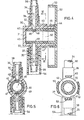
- valve 1 essentially consists of a housing 1, closed at one end, with a cylindrical valve chamber 2, in which a suitable cylindrical plug 3 is arranged, on the closed outer surface of which a regulating groove 4 is formed, which extends over most of its circumference and whose cross-section changes radially continuously over its length.
- the valve chamber 2 is connected to an inlet opening 5 and an outlet opening 6 in the wall of the housing 1, which lie opposite each other and are each extended by a connection piece 7, 8 on which a flexible hose part 9, 10 is inserted.
- the upper hose part 9 comes from a conventional transmission device, for example a drip chamber, while the lower hose part 10 of the liquid line leads to the patient.
- a handle with the rotation of the plug 3 is a circular disk 11 which is formed in one piece with its one end and is knurled on its entire circumference and whose axis of rotation 12 is transverse to the longitudinal axis of the hose parts 9, 10.
- the circular disk 11 is therefore parallel to a rigid handle 13 which is plugged onto the outlet opening 6 on a sleeve 22 surrounding the end of the hose part.
- the handle 13 is about the hand's length and consists of a straight tube with a circular cross section open at both ends, the inside diameter of which corresponds approximately to the outside diameter of the hose part 10.
- a longitudinal slot 14, which extends over the entire length of the handle 13, is used to insert the hose part 10 into the handle 13.
- the longitudinal slot 14 is preferably directed sideways or rearward with respect to the housing 1.
- the handle 13 is gripped with one hand and for regulation the circular disk 11 is rotated with the thumb and index finger of the same hand to actuate the plug 3. In this way, convenient one-hand operation of the drop control device is possible.
- the grip 17 is designed as a tubular sleeve with a circumferentially closed wall.
- the hose line 10 is pushed axially through this grip piece 17 to be plugged onto the socket 8 of the housing 1.
- the two curved slots 23 and 24 in the circular disks 11 and 18 of FIGS. 2 and 3 lighten the weight of the circular disks and contribute to material savings.
- a housing 30 with a cylindrical valve chamber is closed at one end by a wall 31, while its other end is open.
- an inlet opening 32 and an outlet opening 33 are formed offset from one another by 180 °, each of which is extended to the outside by a connecting piece 34, 35, which are circumferentially spaced by a shorter sleeve 36, 37.
- a flexible hose part 38, 39 is plugged onto each connection piece 34, 35, the end of which is appropriately received by the space between the connection piece 34, 35 and the sleeve 36, 37.
- a straight tongue 40, 41 projects from each sleeve 36, 37 and does not touch the outer surface of the wall of the housing 30 and extends parallel to it in the form of a narrow, flat plate.
- a cylindrical hollow plug 42 is inserted so far into its cylindrical valve space that its open end 43 lies tight against the inner surface of the wall 31 of the housing 30.
- an edge bead 44 engages on the outer circumference of the open end of the housing 30 in an adapted annular groove in a cap 45 which is attached to the wall of the housing 30 and is formed in one piece with the plug 42.
- two identical holes 46, 47 are formed, the shape, diameter and arrangement of which essentially correspond to those of the inlet and outlet openings 32, 33 of the housing 30.
- the plug 42 is rotated so that the openings 32, 46, 47 and 33 are coaxially aligned with one another, the largest throughflow opening of the drop control device is set, the flow passing through the cavity of the plug 42.
- two regulating grooves 48, 49 are provided, which are formed in the outer surface of the plug 42 and which, starting from a hole 46 or 47, extend in the circumferential direction.
- the regulating groove 48, 49 has an approximately rectangular cross section and its depth gradually decreases in the circumferential direction, starting from the edge of the associated hole 46 or 47.
- the two regulating grooves 48, 49 are directed in opposite directions with respect to one another and their length is dimensioned such that a rotation of the plug 42 in a clockwise direction by a maximum of 90 ° is sufficient to set the largest throughflow opening until it is completely closed.
- the closed position is reached as soon as the flat end of each regulating groove 48, 49 passing into the circumferential surface of the plug 42 reaches the region of the inner wall surface of the housing 30 on opposite sides of the openings 32, 33.
- the tongues 40, 41 cooperate with curved tongues 50, 51 which project axially from the edge of the cap 45 and are offset from one another by 180 °.
- the plug 42, the cap 45 and the tongues 50, 51 are formed in one piece with a hat-shaped circular disc 52 which has a circumferential knurling 53 on the outer circumference of its axially directed wall.
- a tubular handle 54 is plugged onto the sleeve 37 at the outlet opening 33 of the housing 30, which stiffens the tube part 39 over an approximately hand-long piece and which can be gripped with three fingers while the thumb and index finger of the same hand adjust the circular disk 52.
- a slot 55 is formed, the width and depth of the tongue 41 is adapted so that it receives it and the end face of the edge of the handle 54 rests against the outer surface of the wall of the housing 30.
- the tongue 41 countersunk in the slot 55 which, as can be seen in FIG. 4, protrudes a short distance beyond the outer surface of the handle 54, thus serves not only as a stop element for the two tongues 50, 51 on the circular disk 52, but is also effective as a fixation that prevents rotation of the housing 30 relative to the handle 54 when the circular disc 52 is adjusted.
Landscapes
- Engineering & Computer Science (AREA)
- General Engineering & Computer Science (AREA)
- Health & Medical Sciences (AREA)
- Mechanical Engineering (AREA)
- Biomedical Technology (AREA)
- Life Sciences & Earth Sciences (AREA)
- Vascular Medicine (AREA)
- Anesthesiology (AREA)
- Physics & Mathematics (AREA)
- Heart & Thoracic Surgery (AREA)
- Hematology (AREA)
- Fluid Mechanics (AREA)
- Animal Behavior & Ethology (AREA)
- General Health & Medical Sciences (AREA)
- Public Health (AREA)
- Veterinary Medicine (AREA)
- Infusion, Injection, And Reservoir Apparatuses (AREA)
- Peptides Or Proteins (AREA)
Applications Claiming Priority (2)
| Application Number | Priority Date | Filing Date | Title |
|---|---|---|---|
| DE8312029U | 1983-04-23 | ||
| DE19838312029U DE8312029U1 (de) | 1983-04-23 | 1983-04-23 | Tropfenregelgeraet |
Publications (1)
| Publication Number | Publication Date |
|---|---|
| EP0123079A1 true EP0123079A1 (de) | 1984-10-31 |
Family
ID=6752644
Family Applications (1)
| Application Number | Title | Priority Date | Filing Date |
|---|---|---|---|
| EP84102426A Withdrawn EP0123079A1 (de) | 1983-04-23 | 1984-03-07 | Tropfenregelgerät |
Country Status (8)
| Country | Link |
|---|---|
| EP (1) | EP0123079A1 (da) |
| JP (1) | JPS59207160A (da) |
| BR (1) | BR8401323A (da) |
| DE (1) | DE8312029U1 (da) |
| DK (1) | DK78384A (da) |
| ES (1) | ES278432Y (da) |
| FI (1) | FI840407A7 (da) |
| NO (1) | NO840660L (da) |
Cited By (9)
| Publication number | Priority date | Publication date | Assignee | Title |
|---|---|---|---|---|
| EP0552854A1 (de) * | 1992-01-21 | 1993-07-28 | Andreas Mommer | Dosiervorrichtung für übertragungsgeräte der Infusions- und Transfusionstechnik |
| WO1995000194A1 (en) * | 1993-06-23 | 1995-01-05 | Plasti Medical S.P.A. | High-precision flow regulator for medicinal infusion lines |
| EP1415675A1 (de) * | 2002-10-29 | 2004-05-06 | Smiths Medical Deutschland GmbH | Ventil zum Einstellen des Volumenstromes bei einem Infusions- oder Transfusionsvorgang |
| EP1778317A4 (en) * | 2004-07-16 | 2008-10-01 | Meinntech Co Ltd | DEVICE FOR REGULATING INJECTION VOLUME OF A LIQUID MEDICINAL PRODUCT |
| DE10004142B4 (de) * | 1999-02-01 | 2010-08-19 | Hainzmann, Hubert, Ing. | Stellarmatur mit einem in einem Gehäuse drehbaren Stellorgan |
| WO2022123113A1 (en) * | 2020-12-10 | 2022-06-16 | Monidor Oy | Mechanical infusion fluid flow regulator |
| WO2022244003A1 (en) | 2021-05-19 | 2022-11-24 | Origin Medical Devices Inc. | Variable orifice rotary valve for controlling gas flow |
| US20230264011A1 (en) * | 2018-12-07 | 2023-08-24 | Fresenius Medical Care Holdings, Inc. | Rotary valves for managing fluid flows in medical systems |
| US12013050B2 (en) | 2018-07-31 | 2024-06-18 | Fresenius Medical Care Holdings, Inc. | Rotary valves for dialysis systems |
Families Citing this family (13)
| Publication number | Priority date | Publication date | Assignee | Title |
|---|---|---|---|---|
| JPH0657256B2 (ja) * | 1985-04-26 | 1994-08-03 | 川澄化学工業株式会社 | クランプ |
| DE3727816A1 (de) * | 1986-12-15 | 1988-06-23 | Berg Extrakorp Syst Medtech | Dosierventil zur einstellung der durchflussrate einer fluessigkeitsstroemung in den oder aus dem koerper eines lebewesens |
| DE3700502A1 (de) * | 1986-12-15 | 1988-07-07 | Berg Extrakorp Syst Medtech | Dosiereinrichtung zur einstellung der durchflussrate einer fluessigkeitsstroemung in den oder aus dem koerper eines lebewesens |
| JPH052196Y2 (da) * | 1987-12-18 | 1993-01-20 | ||
| DE4340191C1 (de) * | 1993-11-25 | 1995-02-23 | Matthias Faensen Gmbh & Co Kg | Vorrichtung zur Regulierung des Volumenstromes bei einem Infusions- oder Transfusionsvorgang |
| KR20020085131A (ko) * | 2001-05-04 | 2002-11-16 | 이상빈 | 링거액 주입량 조절장치 |
| KR100472044B1 (ko) * | 2001-11-29 | 2005-03-08 | 메인텍 주식회사 | 약액 주입량 조절장치 |
| KR100578001B1 (ko) * | 2004-05-03 | 2007-11-30 | (주)이화바이오메딕스 | 약액 유량 조절기 |
| US7690396B2 (en) * | 2006-07-20 | 2010-04-06 | Baxter International Inc. | Multirate tubing flow restrictor |
| CN104740724A (zh) * | 2013-12-27 | 2015-07-01 | 苏州和林精密科技有限公司 | 医用表盘式精密流量调节器 |
| WO2016101858A1 (zh) * | 2014-12-22 | 2016-06-30 | 胡绍勤 | 一种输液流速调节器 |
| WO2016101860A1 (zh) * | 2014-12-22 | 2016-06-30 | 胡绍勤 | 一种输液流速调节器 |
| IT202400002214A1 (it) * | 2024-02-02 | 2025-08-02 | Borla Ind | Dispositivo medicale per linee di infusione e trasfusione |
Citations (8)
| Publication number | Priority date | Publication date | Assignee | Title |
|---|---|---|---|---|
| GB818646A (en) * | 1956-03-07 | 1959-08-19 | Koppers Gmbh Heinrich | Improvements in flow-regulating stop cocks |
| CH340681A (de) * | 1955-04-18 | 1959-08-31 | J S Schatt Gmbh Armaturenfabri | Durchlasshahn mit Feineinstellung |
| US3982534A (en) * | 1975-01-10 | 1976-09-28 | Buckman Thomas P | Intravenous administration system |
| DE2735955A1 (de) * | 1977-08-10 | 1979-02-22 | Ender Rudolf | Dosiervorrichtung fuer uebertragungsgeraete der infusions- und transfusionstechnik |
| WO1982000327A1 (en) * | 1980-07-14 | 1982-02-04 | Whitman Med Corp | Adjustable in-line intravenous valve with locking mechanism |
| GB2097514A (en) * | 1981-04-24 | 1982-11-03 | Bespak Industries Ltd | Flow regulating apparatus |
| US4361147A (en) * | 1979-01-22 | 1982-11-30 | Master Medical Corporation | Flow control device for administration of intravenous fluids |
| DE3139030C1 (de) * | 1981-10-01 | 1983-04-14 | B. Braun Melsungen Ag, 3508 Melsungen | Vorrichtung zur Regulierung der Durchflußmenge eines flexiblen Rohres |
-
1983
- 1983-04-23 DE DE19838312029U patent/DE8312029U1/de not_active Expired
-
1984
- 1984-02-01 FI FI840407A patent/FI840407A7/fi not_active Application Discontinuation
- 1984-02-20 DK DK78384A patent/DK78384A/da not_active Application Discontinuation
- 1984-02-22 NO NO840660A patent/NO840660L/no unknown
- 1984-03-07 EP EP84102426A patent/EP0123079A1/de not_active Withdrawn
- 1984-03-22 BR BR8401323A patent/BR8401323A/pt unknown
- 1984-03-27 ES ES1984278432U patent/ES278432Y/es not_active Expired
- 1984-04-19 JP JP59080012A patent/JPS59207160A/ja active Pending
Patent Citations (8)
| Publication number | Priority date | Publication date | Assignee | Title |
|---|---|---|---|---|
| CH340681A (de) * | 1955-04-18 | 1959-08-31 | J S Schatt Gmbh Armaturenfabri | Durchlasshahn mit Feineinstellung |
| GB818646A (en) * | 1956-03-07 | 1959-08-19 | Koppers Gmbh Heinrich | Improvements in flow-regulating stop cocks |
| US3982534A (en) * | 1975-01-10 | 1976-09-28 | Buckman Thomas P | Intravenous administration system |
| DE2735955A1 (de) * | 1977-08-10 | 1979-02-22 | Ender Rudolf | Dosiervorrichtung fuer uebertragungsgeraete der infusions- und transfusionstechnik |
| US4361147A (en) * | 1979-01-22 | 1982-11-30 | Master Medical Corporation | Flow control device for administration of intravenous fluids |
| WO1982000327A1 (en) * | 1980-07-14 | 1982-02-04 | Whitman Med Corp | Adjustable in-line intravenous valve with locking mechanism |
| GB2097514A (en) * | 1981-04-24 | 1982-11-03 | Bespak Industries Ltd | Flow regulating apparatus |
| DE3139030C1 (de) * | 1981-10-01 | 1983-04-14 | B. Braun Melsungen Ag, 3508 Melsungen | Vorrichtung zur Regulierung der Durchflußmenge eines flexiblen Rohres |
Cited By (11)
| Publication number | Priority date | Publication date | Assignee | Title |
|---|---|---|---|---|
| EP0552854A1 (de) * | 1992-01-21 | 1993-07-28 | Andreas Mommer | Dosiervorrichtung für übertragungsgeräte der Infusions- und Transfusionstechnik |
| WO1995000194A1 (en) * | 1993-06-23 | 1995-01-05 | Plasti Medical S.P.A. | High-precision flow regulator for medicinal infusion lines |
| DE10004142B4 (de) * | 1999-02-01 | 2010-08-19 | Hainzmann, Hubert, Ing. | Stellarmatur mit einem in einem Gehäuse drehbaren Stellorgan |
| EP1415675A1 (de) * | 2002-10-29 | 2004-05-06 | Smiths Medical Deutschland GmbH | Ventil zum Einstellen des Volumenstromes bei einem Infusions- oder Transfusionsvorgang |
| EP1778317A4 (en) * | 2004-07-16 | 2008-10-01 | Meinntech Co Ltd | DEVICE FOR REGULATING INJECTION VOLUME OF A LIQUID MEDICINAL PRODUCT |
| US12013050B2 (en) | 2018-07-31 | 2024-06-18 | Fresenius Medical Care Holdings, Inc. | Rotary valves for dialysis systems |
| US20230264011A1 (en) * | 2018-12-07 | 2023-08-24 | Fresenius Medical Care Holdings, Inc. | Rotary valves for managing fluid flows in medical systems |
| US12194268B2 (en) * | 2018-12-07 | 2025-01-14 | Fresenius Medical Care Holdings, Inc. | Rotary valves for managing fluid flows in medical systems |
| WO2022123113A1 (en) * | 2020-12-10 | 2022-06-16 | Monidor Oy | Mechanical infusion fluid flow regulator |
| WO2022244003A1 (en) | 2021-05-19 | 2022-11-24 | Origin Medical Devices Inc. | Variable orifice rotary valve for controlling gas flow |
| EP4352392A4 (en) * | 2021-05-19 | 2024-11-13 | Origin Medical Devices Inc. | VARIABLE ORIFICE ROTARY VALVE FOR REGULATING A GAS FLOW |
Also Published As
| Publication number | Publication date |
|---|---|
| ES278432U (es) | 1984-09-16 |
| DK78384A (da) | 1984-10-24 |
| BR8401323A (pt) | 1985-02-26 |
| ES278432Y (es) | 1985-03-16 |
| FI840407A7 (fi) | 1984-10-24 |
| NO840660L (no) | 1984-10-24 |
| DE8312029U1 (de) | 1983-08-18 |
| FI840407A0 (fi) | 1984-02-01 |
| JPS59207160A (ja) | 1984-11-24 |
| DK78384D0 (da) | 1984-02-20 |
Similar Documents
| Publication | Publication Date | Title |
|---|---|---|
| DE8312029U1 (de) | Tropfenregelgeraet | |
| DE2420966C2 (de) | Dosiervorrichtung | |
| DE3590339C2 (da) | ||
| DE3146541C2 (da) | ||
| DE69305376T2 (de) | Injektionsstift mit verbesserter Dosiereinrichtung | |
| DE69704513T2 (de) | Baueinheit aus Spritze und Nadelschutz | |
| EP0901003B2 (de) | Flaschendispenser | |
| DE8912490U1 (de) | Chirurgische Sonden- und Absaugvorrichtung | |
| DE1653870B2 (de) | Schlauchpumpe | |
| DE3028354A1 (de) | Spritze | |
| DE2702539A1 (de) | Vorrichtung zur abgabe von fluessigkeit in genau vorherbestimmten mengen | |
| DE2527351C3 (de) | Revolverhalfter | |
| DE202014001136U1 (de) | Injektionsgerät | |
| EP3711792B1 (de) | Tropfkammeranordnung für ein medizinisches infusionsgerät | |
| EP0208158A1 (de) | Vorrichtung zum dosierten Ausbringen von Dentalmasse | |
| EP0530471A1 (de) | Stellvorrichtung für ein Mischventil | |
| DE2945432C1 (de) | Sicherheitsbrenner zum Pulverflammspritzen | |
| DE1657210B1 (de) | Abfuell- und Siphongeraet zum Zapfen von Fluessigkeiten | |
| DE3343867C2 (de) | Vorrichtung zur lösbaren Befestigung des Aufsatzes eines chirurgischen Instruments | |
| DE3030579C2 (de) | Venenverweilkatheter | |
| EP0271785B1 (de) | Dosiereinrichtung zur Einstellung der Durchflussrate einer Flüssigkeitsströmung in den oder aus dem Körper eines Lebewesens | |
| DE9218204U1 (de) | Flaschendispenser | |
| EP3338862B1 (de) | Dosiervorrichtung für feuerlöschzwecke | |
| DE4002089C2 (da) | ||
| DE3727816C2 (da) |
Legal Events
| Date | Code | Title | Description |
|---|---|---|---|
| PUAI | Public reference made under article 153(3) epc to a published international application that has entered the european phase |
Free format text: ORIGINAL CODE: 0009012 |
|
| AK | Designated contracting states |
Designated state(s): AT BE CH DE FR GB IT LI LU NL SE |
|
| STAA | Information on the status of an ep patent application or granted ep patent |
Free format text: STATUS: THE APPLICATION IS DEEMED TO BE WITHDRAWN |
|
| 18D | Application deemed to be withdrawn |
Effective date: 19850702 |
|
| RIN1 | Information on inventor provided before grant (corrected) |
Inventor name: LESEMANN, EGON |