EP0123101A2 - Culasse pour moteur à combustion interne alternatif à refroissement par air - Google Patents
Culasse pour moteur à combustion interne alternatif à refroissement par air Download PDFInfo
- Publication number
- EP0123101A2 EP0123101A2 EP84102773A EP84102773A EP0123101A2 EP 0123101 A2 EP0123101 A2 EP 0123101A2 EP 84102773 A EP84102773 A EP 84102773A EP 84102773 A EP84102773 A EP 84102773A EP 0123101 A2 EP0123101 A2 EP 0123101A2
- Authority
- EP
- European Patent Office
- Prior art keywords
- air
- cylinder
- combustion engine
- internal combustion
- cooling
- Prior art date
- Legal status (The legal status is an assumption and is not a legal conclusion. Google has not performed a legal analysis and makes no representation as to the accuracy of the status listed.)
- Granted
Links
Images

Classifications
-
- F—MECHANICAL ENGINEERING; LIGHTING; HEATING; WEAPONS; BLASTING
- F02—COMBUSTION ENGINES; HOT-GAS OR COMBUSTION-PRODUCT ENGINE PLANTS
- F02F—CYLINDERS, PISTONS OR CASINGS, FOR COMBUSTION ENGINES; ARRANGEMENTS OF SEALINGS IN COMBUSTION ENGINES
- F02F1/00—Cylinders; Cylinder heads
- F02F1/24—Cylinder heads
- F02F1/26—Cylinder heads having cooling means
- F02F1/28—Cylinder heads having cooling means for air cooling
- F02F1/30—Finned cylinder heads
- F02F1/32—Finned cylinder heads the cylinder heads being of overhead valve type
Definitions
- the invention relates to an air-cooled reciprocating internal combustion engine with at least one row of cylinders and juxtaposed, essentially cubic single cylinder heads, with slugs for receiving fastening screws, at least one intake and exhaust valve, the valve stems being aligned essentially parallel to the cylinder axis and by the The plane of the valve stems is rotated at an acute angle to the longitudinal direction of the internal combustion engine, the inlet duct begins on the side against which the cooling air flows, approximately in the middle of the cylinder head, and the outlet duct is oriented essentially perpendicular to the exhaust air side, with a lateral guide plate on the last cylinder heads of each row is provided.
- a generic air-cooled reciprocating internal combustion engine with corresponding single cylinder heads is known from the engine series 924 to 930 from Tatra-Werke, CSSR, and in the specialist book "Air-cooled vehicle engines by J. Mackerle, Frank'sche publishing house, Stuttgart, 1964" on pages 171 to 173 and 524 to 528 shown and described.
- the cylinder heads and the cooling fins are designed in such a way that each cylinder head forms a cooling unit and is flowed through in a substantially straight line.
- One cylinder head like the side baffles, only forms one loading limit for the air flow to the other cylinder head.
- the head is only for limited services suitable, especially as the area of the outlet channel and the areas located between outlet passage and the cylinder tube can not be sufficiently cooled. This is also because the slugs for the fastening anchors of the cylinder head on the crankcase are guided up to the upper edge of the cylinder head.
- the object of the present invention is therefore to improve the air-cooled reciprocating internal combustion engine according to the generic term or its cylinder heads and their cooling in such a way that higher outputs can be achieved so that the cylinder head remains strong, good cooling air flow with good cooling of the hot Best places are reached and inexpensive production is possible.
- the object of the invention is achieved in that adjacent cylinder heads by means of the outer contours of the gas exchange channels in connection with central areas arranged between the valve stems and with cooling fins oriented transversely to the cylinder axis, one or, depending on the size of the cooling fins, a plurality of curved or S-shaped cooling air channels in the cylinder Form cylinder head section and that the cover plate section of the cylinder head facing the cylinder is provided on the circumference essentially on the exhaust air side and on the side opposite the inlet valve stem with cooling fins and has the slugs for the fastening screws.
- the cylinder head according to the invention is in one piece, but can be in a cylinder head section facing away from the cylinder (fin section) and in the cover plate section (deck section) can be divided.
- the cover plate section is so thick that sufficient strength is achieved and an overall stable, uniform seal to the cylinder tube is achieved.
- the slugs for the fastening screws of the cylinder head also end with the cover plate section, so that the cylinder head section above it, which faces away from the cylinder, is determined by the gas exchange channels and cooling fins and a central area.
- the plane leading through the valve stems is preferably rotated by 30 ° to the longitudinal direction of the internal combustion engine.
- the locking plates in the area of the cover plate section between two cylinder heads have recesses through which the air flow guided between the cover plate sections can escape.
- the side baffles also have widenings which correspond to the guidance by a further cylinder head. They are also advantageously integrally connected to the corresponding part of the locking plate.
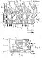
- 1 designates a single cylinder head of an air-cooled reciprocating internal combustion engine, which is essentially cube-shaped in its outer shape and has an inlet channel denoted by 2 and an outlet channel denoted by 3, which extend on opposite sides of the cylinder head 1 .
- the inlet channel 2 and the outlet channel 3 are controlled by inlet valves, not shown, which limit the channels at their end facing the cylinder, not shown.
- the cylinder heads 1 are also not shown, but in FIGS. 1, 3 and 4, the flow of cooling air flows towards them, which is supplied on the inlet side of the inlet duct and leaves the cylinder heads on the outlet duct side.
- the plane running through the valve stems of the valves, not shown, is rotated at an angle of 30 ° to the longitudinal direction of the internal combustion engine.
- the inlet duct 1 begins in the middle of the cylinder head and leads, passing into a swirl duct, to the outside of the cylinder head.
- the exhaust duct 3 is guided to the outside on the shortest path and therefore opens offset to the center of the cylinder head perpendicular to the exhaust side of the cylinder head 1.
- a central region 4 is provided, which in the Embodiment of the invention is made solid and in one piece with the cylinder head.
- This configuration of the cylinder heads creates an arc-shaped or S-shaped cooling air duct 5 in connection with the adjacent cylinder head, in which the cooling air is deflected several times and is therefore optimally utilized.
- the cylinder head has, as can be seen in particular from FIGS. 1 and 2, a cover plate section 6, which is not a Darge facing the cylinder and is essentially solid with little ribbing, and a cylinder head section 7 facing away from the cylinder.
- the cylinder head section 7 has cooling fins 8 which are aligned substantially perpendicular to the cylinder axis and from the channels 2 and 3 or the central region 4 to the cube-shaped outer contour of the cylinder heads.
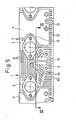
- the D eckplattenabites 6 has at its corners slug 9 for fixing screws, which are shown in Fig. 5.
- the cover plate section 6, which can be seen in particular from FIGS. 1 and 4, has oblique ribs 8a on the side shown there, opposite the inlet channel 2, which are oriented at an acute angle to the cylinder axis. Between these inclined ribs 8a and the cylinder (not shown), which can also be seen in FIG. 2, there is a channel 10 in which channel ribs 8b are arranged.
- the channel 10 is widened in connection with the inclined ribs and the channel ribs, so that the combined partial air flows, as can be seen from FIG. 4, can flow off.
- the adjacent cylinder head can have an adapted recess on the adjacent side.
- the cover plate section 6 has on the exhaust side at an acute angle to the cylinder axis and V-shaped under the outlet channel 3 V-ribs 8c, which are followed by parallel ribs 8d aligned parallel to the cylinder axis.
- the incoming cold air (outlined arrows) is divided into a main air flow, which is the arc-shaped or S-shaped cooling air flows through and into a partial air flow that flows laterally through the cover plate section.
- the cooling air heats up on the walls of the cylinder head and exits as heated air (arrows drawn in bold).
- Z wipe two cylinder heads provided on the exhaust side of a barrier sheet designated 11, which, see F ig. 5, has a throughflow distance on the side and to the edge of the cylinder heads facing the cylinders, as a result of which the cooling air quantity is throttled and also flows around the cylinder head completely on the exhaust air side for the purpose of good cooling effect.
- the locking plate 11 has a recess 13 through which the cooling air flow coming from the lateral ribs of the cover plate section 6 can exit.
- the locking plate 11 is bent at a right angle in the region of the upper edge of the cylinder heads and follows the upper contour of the cylinder heads (FIG. 4). This will make the bow or S-shaped. Cooling air channel limited upwards and cooling air also led to the cooling fins of the cover plate section 6 on the exhaust side below the outlet channel 3.
- baffles 14 are provided, which are shaped so that they replace the outer contour of an adjacent cylinder head and each part of the corresponding locking plate, so that the arc-shaped or S-shaped cooling air duct is retained.
- This configuration of the cylinder heads results in a very good cooling air flow and a very good utilization of the cooling air, so that the central area can be made solid and an injection nozzle of a self-igniting diesel internal combustion engine can be used in a bore 15 in the central area at an optimal combustion point that the injector overheats.
Landscapes
- Engineering & Computer Science (AREA)
- Chemical & Material Sciences (AREA)
- Combustion & Propulsion (AREA)
- Mechanical Engineering (AREA)
- General Engineering & Computer Science (AREA)
- Cylinder Crankcases Of Internal Combustion Engines (AREA)
Priority Applications (1)
| Application Number | Priority Date | Filing Date | Title |
|---|---|---|---|
| AT84102773T ATE31105T1 (de) | 1983-04-22 | 1984-03-14 | Zylinderkopf fuer eine luftgekuehlte hubkolbenbrennkraftmaschine. |
Applications Claiming Priority (2)
| Application Number | Priority Date | Filing Date | Title |
|---|---|---|---|
| DE3314720 | 1983-04-22 | ||
| DE19833314720 DE3314720A1 (de) | 1983-04-22 | 1983-04-22 | Zylinderkopf fuer eine luftgekuehlte hubkolbenbrennkraftmaschine |
Publications (3)
| Publication Number | Publication Date |
|---|---|
| EP0123101A2 true EP0123101A2 (fr) | 1984-10-31 |
| EP0123101A3 EP0123101A3 (en) | 1985-11-13 |
| EP0123101B1 EP0123101B1 (fr) | 1987-11-25 |
Family
ID=6197143
Family Applications (1)
| Application Number | Title | Priority Date | Filing Date |
|---|---|---|---|
| EP84102773A Expired EP0123101B1 (fr) | 1983-04-22 | 1984-03-14 | Culasse pour moteur à combustion interne alternatif à refroissement par air |
Country Status (5)
| Country | Link |
|---|---|
| EP (1) | EP0123101B1 (fr) |
| JP (1) | JPS59206652A (fr) |
| AT (1) | ATE31105T1 (fr) |
| CA (1) | CA1232501A (fr) |
| DE (2) | DE3314720A1 (fr) |
Cited By (3)
| Publication number | Priority date | Publication date | Assignee | Title |
|---|---|---|---|---|
| EP1391583A1 (fr) * | 2002-08-23 | 2004-02-25 | MAN Turbomaschinen AG | Conduit de transition refroidi par air |
| CN102400811A (zh) * | 2011-12-19 | 2012-04-04 | 力帆实业(集团)股份有限公司 | 三气门发动机气缸头 |
| WO2025098473A1 (fr) * | 2023-11-09 | 2025-05-15 | 长城汽车股份有限公司 | Culasse, moteur et véhicule |
Families Citing this family (2)
| Publication number | Priority date | Publication date | Assignee | Title |
|---|---|---|---|---|
| JPS62197658A (ja) * | 1986-02-24 | 1987-09-01 | Yanmar Diesel Engine Co Ltd | 内燃機関のシリンダヘツド冷却装置 |
| CN116255268B (zh) * | 2023-03-22 | 2026-01-27 | 重庆润通科技有限公司 | 一种发动机缸头 |
Family Cites Families (10)
| Publication number | Priority date | Publication date | Assignee | Title |
|---|---|---|---|---|
| BE544548A (fr) * | ||||
| DE862690C (de) * | 1943-10-19 | 1953-01-12 | Kloeckner Humboldt Deutz Ag | Kuehlluftfuehrung am Zylinderkopf von luftgekuehlten Brennkraftmaschinen mit einem Nebenraum |
| DE970978C (de) * | 1952-04-13 | 1958-11-20 | Kloeckner Humboldt Deutz Ag | Luftgekuehlter Zylinderkopf fuer Brennkraftmaschinen |
| AT185623B (de) * | 1953-06-12 | 1956-05-25 | Motoren Werke Mannheim Ag | Zylinderkopf für gebläseluftgekühlte, ventilgesteuerte Brennkraftmaschinen |
| CH343708A (fr) * | 1957-05-23 | 1959-12-31 | Lister & Co Ltd R A | Moteur à combustion interne et allumage par compression |
| DE1119600B (de) * | 1958-11-15 | 1961-12-14 | Linde S Eismaschinen Ag Zweign | Luftgekuehlter Zylinderkopf fuer Brennkraftmaschinen |
| DE1187425B (de) * | 1959-10-10 | 1965-02-18 | Motoren Werke Mannheim Ag | Zylinderkopf fuer luftgekuehlte Einspritzbrennkraftmaschinen |
| CS163067B1 (fr) * | 1973-03-28 | 1975-07-31 | ||
| DE2523077A1 (de) * | 1975-05-24 | 1976-12-02 | Kloeckner Humboldt Deutz Ag | Zylinderkopf fuer eine luftgekuehlte hubkolbenmaschine |
| AT365743B (de) * | 1977-06-07 | 1982-02-10 | List Hans | Zylinderkopf fuer eine luftgekuehlte brennkraftmaschine |
-
1983
- 1983-04-22 DE DE19833314720 patent/DE3314720A1/de not_active Withdrawn
-
1984
- 1984-03-14 DE DE8484102773T patent/DE3467793D1/de not_active Expired
- 1984-03-14 EP EP84102773A patent/EP0123101B1/fr not_active Expired
- 1984-03-14 AT AT84102773T patent/ATE31105T1/de not_active IP Right Cessation
- 1984-04-19 CA CA000452380A patent/CA1232501A/fr not_active Expired
- 1984-04-20 JP JP59078812A patent/JPS59206652A/ja active Pending
Cited By (5)
| Publication number | Priority date | Publication date | Assignee | Title |
|---|---|---|---|---|
| EP1391583A1 (fr) * | 2002-08-23 | 2004-02-25 | MAN Turbomaschinen AG | Conduit de transition refroidi par air |
| US6996992B2 (en) | 2002-08-23 | 2006-02-14 | Man Turbo Ag | Gas collection pipe carrying hot gas |
| CN102400811A (zh) * | 2011-12-19 | 2012-04-04 | 力帆实业(集团)股份有限公司 | 三气门发动机气缸头 |
| CN102400811B (zh) * | 2011-12-19 | 2013-03-20 | 力帆实业(集团)股份有限公司 | 三气门发动机气缸头 |
| WO2025098473A1 (fr) * | 2023-11-09 | 2025-05-15 | 长城汽车股份有限公司 | Culasse, moteur et véhicule |
Also Published As
| Publication number | Publication date |
|---|---|
| EP0123101B1 (fr) | 1987-11-25 |
| JPS59206652A (ja) | 1984-11-22 |
| DE3467793D1 (en) | 1988-01-07 |
| DE3314720A1 (de) | 1984-10-25 |
| CA1232501A (fr) | 1988-02-09 |
| ATE31105T1 (de) | 1987-12-15 |
| EP0123101A3 (en) | 1985-11-13 |
Similar Documents
| Publication | Publication Date | Title |
|---|---|---|
| DE2756006C2 (fr) | ||
| EP1516113B1 (fr) | Culasse refroidie pour moteur a combustion interne a pistons | |
| DE2839199C2 (de) | Im Druckgießverfahren herstellbarer Zylinderkopf für wassergekühlte Brennkraftmaschinen | |
| DE602004006661T2 (de) | Brennkraftmaschine mit Entlüftungsvorrichtung | |
| DE2417925A1 (de) | Verbrennungskraftmaschine | |
| DE69308768T2 (de) | Zylinderkopf-Kühlstruktur für eine Mehrventil-Brennkraftmaschine | |
| DE10344834B4 (de) | Motorkühlsystem | |
| EP1108878A2 (fr) | Moteur à combustion interne avec un conduit d'admission divisé | |
| EP0771941B2 (fr) | Culasse pour moteur à combustion interne | |
| EP0268988B1 (fr) | Moteur diesel | |
| AT402325B (de) | Zylinderkopf einer flüssigkeitsgekühlten brennkraftmaschine mit in reihe angeordneten zylindern | |
| EP0819837B1 (fr) | Circuit de refroidissement d'un moteur à combustion interne | |
| AT402431B (de) | Zweitakt-brennkraftmaschine | |
| EP0154144B1 (fr) | Moteur à combustion interne refroidi par air | |
| DE2904167C2 (de) | Im Druckgießverfahren herstellbarer Zylinderkopf für wassergekühlte Brennkraftmaschinen | |
| DE102009008237B4 (de) | Brennkraftmaschine mit getrennten Kühlmittelräumen im Zylinderkopf | |
| EP0062143A2 (fr) | Culasse de cylindres pour un moteur à compression d'air, à auto-allumage et à injection | |
| EP0123101B1 (fr) | Culasse pour moteur à combustion interne alternatif à refroissement par air | |
| DE3435386A1 (de) | Luftgekuehlte mehrzylinder-brennkraftmaschine | |
| DE19509002C2 (de) | Thermostatanbaupositionsstruktur | |
| DE69221651T2 (de) | Einlasssystem für eine Brennkraftmaschine | |
| DE4036810C1 (fr) | ||
| DE913718C (de) | Zylinderkopf fuer luftgekuehlte 4-Takt-Dieselmaschinen | |
| DE3116802C2 (de) | Vierventil-Zylinderkopf für einen Viertaktmotor | |
| EP0974003B1 (fr) | Moteur a combustion interne a quatre temps a cylindres multiples |
Legal Events
| Date | Code | Title | Description |
|---|---|---|---|
| PUAI | Public reference made under article 153(3) epc to a published international application that has entered the european phase |
Free format text: ORIGINAL CODE: 0009012 |
|
| AK | Designated contracting states |
Designated state(s): AT DE FR GB IT |
|
| PUAL | Search report despatched |
Free format text: ORIGINAL CODE: 0009013 |
|
| AK | Designated contracting states |
Designated state(s): AT DE FR GB IT |
|
| 17P | Request for examination filed |
Effective date: 19851029 |
|
| 17Q | First examination report despatched |
Effective date: 19860924 |
|
| GRAA | (expected) grant |
Free format text: ORIGINAL CODE: 0009210 |
|
| AK | Designated contracting states |
Kind code of ref document: B1 Designated state(s): AT DE FR GB IT |
|
| PG25 | Lapsed in a contracting state [announced via postgrant information from national office to epo] |
Ref country code: IT Free format text: LAPSE BECAUSE OF FAILURE TO SUBMIT A TRANSLATION OF THE DESCRIPTION OR TO PAY THE FEE WITHIN THE PRESCRIBED TIME-LIMIT;WARNING: LAPSES OF ITALIAN PATENTS WITH EFFECTIVE DATE BEFORE 2007 MAY HAVE OCCURRED AT ANY TIME BEFORE 2007. THE CORRECT EFFECTIVE DATE MAY BE DIFFERENT FROM THE ONE RECORDED. Effective date: 19871125 |
|
| REF | Corresponds to: |
Ref document number: 31105 Country of ref document: AT Date of ref document: 19871215 Kind code of ref document: T |
|
| REF | Corresponds to: |
Ref document number: 3467793 Country of ref document: DE Date of ref document: 19880107 |
|
| ET | Fr: translation filed | ||
| GBT | Gb: translation of ep patent filed (gb section 77(6)(a)/1977) | ||
| PLBE | No opposition filed within time limit |
Free format text: ORIGINAL CODE: 0009261 |
|
| STAA | Information on the status of an ep patent application or granted ep patent |
Free format text: STATUS: NO OPPOSITION FILED WITHIN TIME LIMIT |
|
| 26N | No opposition filed | ||
| PGFP | Annual fee paid to national office [announced via postgrant information from national office to epo] |
Ref country code: DE Payment date: 19910117 Year of fee payment: 8 |
|
| PG25 | Lapsed in a contracting state [announced via postgrant information from national office to epo] |
Ref country code: DE Effective date: 19921201 |
|
| PGFP | Annual fee paid to national office [announced via postgrant information from national office to epo] |
Ref country code: FR Payment date: 19930211 Year of fee payment: 10 Ref country code: AT Payment date: 19930211 Year of fee payment: 10 |
|
| PGFP | Annual fee paid to national office [announced via postgrant information from national office to epo] |
Ref country code: GB Payment date: 19930217 Year of fee payment: 10 |
|
| PG25 | Lapsed in a contracting state [announced via postgrant information from national office to epo] |
Ref country code: GB Effective date: 19940314 Ref country code: AT Effective date: 19940314 |
|
| GBPC | Gb: european patent ceased through non-payment of renewal fee |
Effective date: 19940314 |
|
| PG25 | Lapsed in a contracting state [announced via postgrant information from national office to epo] |
Ref country code: FR Effective date: 19941130 |
|
| REG | Reference to a national code |
Ref country code: FR Ref legal event code: ST |