EP0123117B1 - Verfahren und Vorrichtung zur Herstellung von verstellbaren Trägern - Google Patents
Verfahren und Vorrichtung zur Herstellung von verstellbaren Trägern Download PDFInfo
- Publication number
- EP0123117B1 EP0123117B1 EP84102920A EP84102920A EP0123117B1 EP 0123117 B1 EP0123117 B1 EP 0123117B1 EP 84102920 A EP84102920 A EP 84102920A EP 84102920 A EP84102920 A EP 84102920A EP 0123117 B1 EP0123117 B1 EP 0123117B1
- Authority
- EP
- European Patent Office
- Prior art keywords
- ribbon
- ring
- slider
- unit
- pliers
- Prior art date
- Legal status (The legal status is an assumption and is not a legal conclusion. Google has not performed a legal analysis and makes no representation as to the accuracy of the status listed.)
- Expired
Links
- 238000000034 method Methods 0.000 title claims abstract description 18
- 238000004519 manufacturing process Methods 0.000 title claims abstract description 9
- 238000007789 sealing Methods 0.000 claims abstract description 17
- 238000003780 insertion Methods 0.000 claims abstract description 5
- 230000037431 insertion Effects 0.000 claims abstract description 5
- 230000007306 turnover Effects 0.000 claims abstract description 5
- 238000003892 spreading Methods 0.000 claims abstract 2
- 238000003466 welding Methods 0.000 claims description 17
- 230000000717 retained effect Effects 0.000 claims description 3
- 230000005484 gravity Effects 0.000 claims description 2
- 238000005520 cutting process Methods 0.000 claims 1
- 238000004873 anchoring Methods 0.000 description 4
- 239000004744 fabric Substances 0.000 description 3
- 238000005452 bending Methods 0.000 description 1
- 238000010924 continuous production Methods 0.000 description 1
- 238000006073 displacement reaction Methods 0.000 description 1
- 238000009877 rendering Methods 0.000 description 1
- 239000012858 resilient material Substances 0.000 description 1
- 238000009958 sewing Methods 0.000 description 1
Images





Classifications
-
- A—HUMAN NECESSITIES
- A41—WEARING APPAREL
- A41H—APPLIANCES OR METHODS FOR MAKING CLOTHES, e.g. FOR DRESS-MAKING OR FOR TAILORING, NOT OTHERWISE PROVIDED FOR
- A41H37/00—Machines, appliances or methods for setting fastener-elements on garments
- A41H37/08—Setting buckles
-
- Y—GENERAL TAGGING OF NEW TECHNOLOGICAL DEVELOPMENTS; GENERAL TAGGING OF CROSS-SECTIONAL TECHNOLOGIES SPANNING OVER SEVERAL SECTIONS OF THE IPC; TECHNICAL SUBJECTS COVERED BY FORMER USPC CROSS-REFERENCE ART COLLECTIONS [XRACs] AND DIGESTS
- Y10—TECHNICAL SUBJECTS COVERED BY FORMER USPC
- Y10T—TECHNICAL SUBJECTS COVERED BY FORMER US CLASSIFICATION
- Y10T156/00—Adhesive bonding and miscellaneous chemical manufacture
- Y10T156/10—Methods of surface bonding and/or assembly therefor
- Y10T156/1002—Methods of surface bonding and/or assembly therefor with permanent bending or reshaping or surface deformation of self sustaining lamina
- Y10T156/1043—Subsequent to assembly
- Y10T156/1049—Folding only
Definitions
- This application relates to the manufacture of clothing, particularly brassieres.
- shoulder-straps of adjustable length, made of elastic or not elastic cloth or fabric ribbon.
- the ribbon is bent in loop-like form, a ring or similar means is slipped on the ribbon loop and a slider, generally a two-slot type of slider, is fixed to a ribbon end and slidable with the double slot on another portion of the ribbon forming said loop.
- the ring is then secured to another ribbon or to a cloth border, generally fixed to a brassiere cup.
- the shoulder-strap comprising the same can be either elongated or shortened.
- shoulder-straps are manually effected.
- An operator cuts a ribbon section of predetermined length, slips or threads a first end of the ribbon into the ring, and slides the ring on the ribbon for some length; then he slips or threads said ribbon end into the slider, folds up said ribbon end on itself and fixes it by sewing; then he takes a second end of the ribbon and slips or threads it first in one and then into the other slider slot, so that it remains at sliding condition; thus a shoulder-strap is ready for application to a brassiere.
- An earlier application of the same application (FR-A-2 394 259) describes a ribbon slider comprising an anchoring portion with projections for sealing of welding, for example ultrasonic welding, and a double slot, the two slots' being separated by a bridge portion comprising two arms extended to each other, and resiliently flexible in a plate at right angles to the slider plane.
- Said application also describes an automatic process for assembling a slider and a ribbon, which process comprises the steps of sealing one end of the ribbon onto the slider, then introducing by a punch orthogonal to the slider a ribbon portion into the slider, and finally retracting the slider leaving the ribbon straddling on its arms.
- the novel process and apparatus enable a completely automatic assembling of an adjustable length should-strap for clothing, completed with a ring and a slider and ready for attachment to the clothing item, which assembly takes place in short times, does not involve any labour, exkept but for control, and is highly reliable.
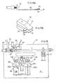
- a shoulder-strap 8 to be manufactured comprises an elastic or not elastic ribbon 1 of any known type; a ring 2 of relatively flexible and resilient material and diameter generally less than or equal to the ribbon width; and a slider 3 of the type as described in the above mentioned earlier application, that is comprising an anchoring portion 4 for anchoring by welding or sealing, slots 5 and 6 separated by elastically deformable arms 7.
- Said ring 2 may be substituted for by a hook element or slider of any known type.
- a shoulder-strap manufacturing apparatus 10 on a frame having a work table 14, comprises a ribbon feeding unit 16, a scissors 17, a ring supplying and squeezing (deforming) unit 18, a slider supply unit 20, a welding or sealing unit 22, a ribbon translation and turnover unit 24 and an inserting and ejecting unit 26 for inserting the ribbon into the slider and ejecting the shoulder strap.
- the unit 16 comprises a supporting means (not shown) forthe supply of a shoulder-strap ribbon 1, for example from a commercially available continuous roll unwound about a roller 29; it further comprises a pliers member 30, or feeding pliers, carried on a block 32 movable on a generally horizontal guide 33 for to an fro travel.
- Said pliers member 30 comprises jaws 34 and 35 openable to each other in any well known manner (not shown); each of said jaws 34 and 35 have at the portion thereof facing the units 18 and 22 a supporting extension integral thereto, respectively 34' and 35' and relatively flat and thin, so that said ribbon 1 can be gripped and held with an end portion thereof substantially horizontally arranged.
- the pliers member is movable between an extreme position beyond the scissors 17, shown in Figs. 2, 3, 6, 7, 8, 14 and 18, and an extreme position adjacent unit 20, shown in Figs. 4, 5,16 and 17. In Fig. 15 such a member is shown at an intermediate position.
- the scissors 17 are mounted at an adjustable position on the frame adjacent and slightly downstream of the extreme position for pliers 30.
- the scissors 17 comprise a pair of blades 41 and 42 which, at the open condition thereof, leave a free space therebetween sufficient for the passage of pliers 30. Opening and closing of the scissors blades is controlled by any well known system to those skilled in the art, for example by a pantograph system controlled by a cylinder-piston.
- the supply unit 18 for supplying rings 2 generally comprises a vibrating feeder, not shown as per se well known, from which the rings 2 aligned one by one are supplied to an inclined guide 51 and therefrom along an inclined channel 52 provided in a side wall 53 of the unit to a substantially horizontal channel 54.
- each ring is individually pushed by an inclined edge pusher 56, having an horizontal reciprocating motion into a seat 55 at the end of said channel 54.
- the pusher is to and fro driven in any well known manner, for example by cylinder-piston 57 shown in Fig. 14.
- a slide 58 is vertically slidable on seat 55 and is reciprocated in vertical direction by any well known means.
- said slide 58 is coupled to a lever 60 pivoted at 61 to a frame 62 of the ring feeding unit.
- a cylinder-piston assembly 64 acts upon said lever 60 and causes said lever and accordingly said slide 58 to be lowered and lifted; on lowering, said slide causes by its lower edge some squeezing of the underlying ring.
- the whole frame 62 of the ring supply and squeezing unit is movable for a to and fro movement to and away from the unit 22 and is carried and guided for movement on the above mentioned guide 33 or on another parallel guide.
- a piece 65, secured at adjustable position on table 14, acts as a stop for said frame 62.
- each ring 2 supplied from a channel 51 a to a seat 55a is squeezed between two vertically movable slides (not shown), each of which is connected to an arm or lever 58a and 58'a, respectively.
- Each arm is pivoted on the frame 62a respectively at 66a and 66'a.
- Awedge 67 movable in the direction shown by the arrows, provides for convergency of the slides, while a spring 68 provides for maintaining such slides away from each other.
- the whole unit 18 may be modified when said rings 2 are substituted for by other equivalent devices, such as hook sliders or rectangle rings.
- the unit 20 generally comprises a vibrating device (not shown, as per se well known), from which the sliders 3 are orderly supplied one by one to an inclined channel 72, arriving therefrom by gravity at a horizontal channel 74 which is transverse to channel 72.
- a pusher member 76 in said channel 74 provides for carrying and individually positioning each slider on a welding or sealing seat 78 atthe channel end.
- Said pusher 76 is driven by a cylinder-piston assembly79 and has a plate 80 having a lower offset 81, so that a shoulder 82 of the plate provides for support of the slider against longitudinal movement and an upper shoulder 83 prevents the slider against vertical displacement.
- the welding or sealing unit 22 may be any well known unit suitable for the intended purpose; particularly, in the example shown, it comprises a horn or ultrasonic welding tool (soundtrode 91), having a substantially rectangular operative surface and arranged on the vertical of seat 78 and vertically movable.
- a control device (not shown), for example a photocell device, controls the presence of a slider 3 in seat 78 and enables soundtrode or tool lowering.
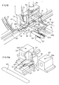
- a body 106 of a translation pliers member 108 is slidable within block 102 between extended and retracted positions.
- Said body 106 has a groove 107 of helical shape on at least part of its extension, for engagement with a fixed state 102a projecting into said body 102 so that, when body 106 moves from extended to retracted position, it also rotates about its own axis through about 180°.
- Pliers 108 comprise two jaws, an upper jaw 109 and a lower jaw 110, which are substantially flat and suitable to be arranged on one side and the other of ribbon 1. Both of the jaws are pivotally supported on body pin 111, and can rotate thereabout to pass from opening to closing positions.
- An opening and closing mechanism may be of any well known type, for example as shown in Fig. 23.
- Said two jaws are provided on the shanks thereof with slots 150 and 152 inclined in opposite direction; on the two opposite sides said body 106 has slots 153 and 154 axially extended, so that a second pin 155 engaged in said slots 150, 152,153 and 154 and to and fro moved causes the opening and closing of the jaws.
- a body 114 of a second translation pliers member 116 is slidable within block 104.
- This body 114 is movable between an extended position of block 104 and a retracted position in said block 104; in the body an-axial rectilinear groove 118 engages in a stake 104a projecting into said block 104 to guide the rectilinear movement of said body 114.
- the two jaws of said pliers 116 are pivoted about the pin 120 on said body 114; opening and closing thereof is controlled by any well known means, for example as above described in connection with Fig. 23.
- the bodies 106 and 114 are integral to each other when advancing and advancement or feeding may be controlled by per se well known means, not shown.
- the unit 26 comprises a plate 121 and a counter-plate 122 secured to said table 14.
- Plate 122 is superimposed to plate 121 and substantially parallel thereto, spaced apart therefrom by a gap at least sufficient to accommodate the thickness of two plies of ribbon 1.
- Both of said plates have aligned through apertures 121' and 122'.
- a first punch 124 is movable at right angles to the extension of said plates and is of such a size as to loosely pass through said apertures and slider.
- a second punch 126 is also movable orthogonally of said plates and is arranged spaced apart from the first punch. The operating means for said first and second punches are not shown as per se well known.
- an ejector means 130 For the ejection of the completed shoulder-strap there is provided an ejector means 130; in the embodiment shown in Fig. 19a said means 130 is of fork type and has two side arms 131 and 132 on the sides of plates 121 and 122 and a central arm 133 arranged between the plates.
- said ejector 130 may comprise only said arm 133.
- the ejector device 130 is movable between an advanced position, at which it provided for ejection of the completed shoulder-strap, and a retracted position (shown in Fig. 19a) at which it does not interfer with the shoulder-strap; the movement is imparted by known means (not shown).
- the ejected shoulder-strap 8 is allowed to fall down into an aperture 140 and collected in a suitable collection vessel or device, not shown.
- the apparatus further comprises control means, not described in detail as per se in the reach of those skilled in the art, to allow the continuation of the operation only in the presence of such elements as ribbon, ring, slider, as required thereto.
- One end of a continuous shoulder-strap ribbon 1 (said end having been sheared by scissors 17) is initially placed within said pliers 30 which are closed and retain it.
- a ring 2 is supplied to seat 55 and by exploiting the elasticity thereof is deformed by slide 58; the temporary deformation of said ring sufficiently increases the width size thereof so that the ribbon 1 can be easily passed therethrough.
- a slider 3 is supplied to seat 78 and retained thereon. The above described steps are shown in Figs. 2, 3, 14 and 15.
- the pliers 30 support the end of ribbon 1, at horizontal arrangement between the extensions 34' and 35' and with a border projecting therefrom; the pliers 30 move between the open blades of scissors 17 and translate to the left as seen in the figures of the drawings; then encounter the unit 18 and provide for slipping or threading the end of said ribbon 1 into the ring 2 deformed between said slide 58 and seat 55; the pliers 30 then continues to advance to the left as seen in the figures of the drawings, accompanied by unit 18, up to a position (Figs. 4, 5 and 17) adjacent the slider seat 78. The units 30 and 18 stop and the end of ribbon 1 is positioned over the anchoring portion of a slider present on said seat 78.
- the tool or soundtrobe 91 is lowered and welds or seals the slider to the ribbon (Figs. 5 and 16).
- pliers 30 On lowering of the soundtrobe to hold the ribbon, pliers 30 open. The pliers 30 move back to the initial position and unit 18 moves back to initial position and pressure is released on ring 2 (situation of Fig. 6).
- the pliers 108 and 116 move forward gripping the ribbon 1 between the units 20 and 18 and between the units 18 and 16, respectively (Figs. 7, 18,19).
- the pliers 108 and 116 are retracted to displace the ribbon, completed with slider and ring, moving it transversely away from the position hitherto occupied towards said plates 121 and 122.
- pliers 108 rotate through 180° about its own body 106, bending said ribbon 1 as loop and bringing the slider to bear on an intermediate portion of ribbon 1, (Fig. 9) which bears on the extended portion of plate 120; ring 2 remains in the loop portion; as the retraction movement of pliers 108 and 116 continues, the intermediate portion of ribbon 1 with the superimposed slider is inserted into the gap between plates 121 and 122, with the slider arm in register with the superimposed apertures of the plates (Figs. 10 and 19a); the first punch 124 is at retracted condition, as well as also the second punch 126.
- Pliers 116 are opened; then the punch 124 is extended (Fig. 11) causing the intermediate portion of the ribbon to be inserted into the slider, deforming the arms of the latter.
- the punch 124 is then retracted, leaving the ribbon astride the arms; now the ribbon forms a loop (Fig. 12) on the slider arms.
- the pliers 116 are closed again and the second punch 126 is operated (Fig. 13) to stretch the ribbon removing the above mentioned loop.
- the punch 126 is then retracted (this step not being shown) and the ejection fork is advanced to eject the shoulder-strap thus formed from the gap between said plates 121 and 122, pushing it over the aperture where the shoulder-strap falls to the collection container. It should be noted that in a continuous process the operations restart from the step shown in Fig. 8.
Landscapes
- Textile Engineering (AREA)
- Engineering & Computer Science (AREA)
- Corsets Or Brassieres (AREA)
- Details Of Garments (AREA)
- Treatment Of Fiber Materials (AREA)
- Seeds, Soups, And Other Foods (AREA)
- Absorbent Articles And Supports Therefor (AREA)
- Packaging Of Machine Parts And Wound Products (AREA)
- Slide Fasteners (AREA)
- Outer Garments And Coats (AREA)
- Slide Fasteners, Snap Fasteners, And Hook Fasteners (AREA)
- Making Paper Articles (AREA)
- Decoration Of Textiles (AREA)
- Basic Packing Technique (AREA)
- Packaging Of Special Articles (AREA)
Claims (17)
Priority Applications (1)
| Application Number | Priority Date | Filing Date | Title |
|---|---|---|---|
| AT84102920T ATE37477T1 (de) | 1983-03-17 | 1984-03-16 | Verfahren und vorrichtung zur herstellung von verstellbaren traegern. |
Applications Claiming Priority (2)
| Application Number | Priority Date | Filing Date | Title |
|---|---|---|---|
| IT2011983 | 1983-03-17 | ||
| IT20119/83A IT1161120B (it) | 1983-03-17 | 1983-03-17 | Procedimento e macchina per confezionamento di spalline regolabili per abbigliamento |
Publications (2)
| Publication Number | Publication Date |
|---|---|
| EP0123117A1 EP0123117A1 (de) | 1984-10-31 |
| EP0123117B1 true EP0123117B1 (de) | 1988-09-28 |
Family
ID=11163958
Family Applications (1)
| Application Number | Title | Priority Date | Filing Date |
|---|---|---|---|
| EP84102920A Expired EP0123117B1 (de) | 1983-03-17 | 1984-03-16 | Verfahren und Vorrichtung zur Herstellung von verstellbaren Trägern |
Country Status (8)
| Country | Link |
|---|---|
| US (1) | US4529463A (de) |
| EP (1) | EP0123117B1 (de) |
| JP (1) | JPS59187603A (de) |
| AT (1) | ATE37477T1 (de) |
| DE (1) | DE3474252D1 (de) |
| ES (1) | ES8501216A1 (de) |
| IT (1) | IT1161120B (de) |
| PT (1) | PT78270B (de) |
Cited By (1)
| Publication number | Priority date | Publication date | Assignee | Title |
|---|---|---|---|---|
| CN108442048A (zh) * | 2018-03-13 | 2018-08-24 | 重庆光大产业有限公司 | 一种安全带带销装配设备 |
Families Citing this family (7)
| Publication number | Priority date | Publication date | Assignee | Title |
|---|---|---|---|---|
| EP0152832B1 (de) * | 1984-02-02 | 1990-11-07 | LOVABLE ITALIANA S.p.A. | Öse für Streifen, insbesondere für Kleidung,Vorrichtung und Verfahren zu ihrer Befestigung |
| FR2598600A1 (fr) * | 1986-05-13 | 1987-11-20 | Martin Christian | Boucle de reglage de la longueur d'un ruban, procede de montage de cette boucle sur le ruban et dispositif pour la mise en oeuvre de ce procede |
| FR2631788B1 (fr) * | 1988-05-31 | 1990-09-07 | Atamec Crozet Fourneyron | Procede et dispositif pour fabriquer des bretelles pour sous-vetements feminins |
| US5984762A (en) * | 1993-12-03 | 1999-11-16 | Playtex Apparel, Inc. | Stretch cushion strap assembly and method and device for making same |
| CA2619547C (en) | 2007-02-06 | 2016-05-17 | Smith International, Inc. | Polycrystalline diamond constructions having improved thermal stability |
| CN103111530B (zh) * | 2013-01-28 | 2016-03-02 | 东阳市双双科技有限公司 | 一种钉扣机 |
| CN110192687B (zh) * | 2019-06-26 | 2024-02-27 | 宁波恒涛日用品工贸有限公司 | 一种全自动打扣机 |
Family Cites Families (12)
| Publication number | Priority date | Publication date | Assignee | Title |
|---|---|---|---|---|
| US2699275A (en) * | 1951-04-12 | 1955-01-11 | Johnson & Johnson | Method and machine for applying buckles and product |
| US2955730A (en) * | 1958-12-17 | 1960-10-11 | Scovill Manufacturing Co | Buckle threading apparatus |
| US3033728A (en) * | 1959-09-22 | 1962-05-08 | Lehigh Ind Inc | Apparatus for sealing a loop of ribbon |
| US3150804A (en) * | 1963-02-18 | 1964-09-29 | Index Ind Inc | Apparatus for forming a closed loop of tape threaded through a buckle |
| US3587947A (en) * | 1969-09-24 | 1971-06-28 | Undergarment Assemblies Inc | Apparatus for making a buckle and strap assembly |
| US3785907A (en) * | 1971-04-05 | 1974-01-15 | American Safety Equip | Method and apparatus for automatic assembly of a belt and anchor plate |
| GB1547576A (en) * | 1976-05-04 | 1979-06-20 | Canadian Lady Canadelle | Apparatus for sewing rings buckles and like elements onto tape |
| GB1547578A (en) * | 1976-05-04 | 1979-06-20 | Canadian Lady Canadelle | Machine for making shoulder straps of garments |
| IT1114880B (it) * | 1977-06-17 | 1986-01-27 | Lovable Italiana Spa | Cursore per nastri e simili |
| AT357970B (de) * | 1978-03-23 | 1980-08-11 | Triumph International Ag | Vorrichtung zur befestigung von oesenteilen auf baendern |
| GB2041998A (en) * | 1979-02-06 | 1980-09-17 | Gateway Industries | Method and apparatus for automatically sewing belts |
| FR2515009A1 (fr) * | 1981-10-23 | 1983-04-29 | Mecanique Ste Forezienne | Procede et moyens d'enfilage des boucles sur des bretelles, et notamment des bretelles de soutiens-gorge et autres sous-vetements et vetements |
-
1983
- 1983-03-17 IT IT20119/83A patent/IT1161120B/it active
-
1984
- 1984-03-16 PT PT78270A patent/PT78270B/pt unknown
- 1984-03-16 EP EP84102920A patent/EP0123117B1/de not_active Expired
- 1984-03-16 ES ES530734A patent/ES8501216A1/es not_active Expired
- 1984-03-16 DE DE8484102920T patent/DE3474252D1/de not_active Expired
- 1984-03-16 AT AT84102920T patent/ATE37477T1/de not_active IP Right Cessation
- 1984-03-16 JP JP59052048A patent/JPS59187603A/ja active Pending
- 1984-03-19 US US06/590,622 patent/US4529463A/en not_active Expired - Fee Related
Cited By (2)
| Publication number | Priority date | Publication date | Assignee | Title |
|---|---|---|---|---|
| CN108442048A (zh) * | 2018-03-13 | 2018-08-24 | 重庆光大产业有限公司 | 一种安全带带销装配设备 |
| CN108442048B (zh) * | 2018-03-13 | 2021-03-23 | 重庆光大产业有限公司 | 一种安全带带销装配设备 |
Also Published As
| Publication number | Publication date |
|---|---|
| IT1161120B (it) | 1987-03-11 |
| PT78270B (en) | 1986-05-20 |
| EP0123117A1 (de) | 1984-10-31 |
| JPS59187603A (ja) | 1984-10-24 |
| DE3474252D1 (en) | 1988-11-03 |
| ES530734A0 (es) | 1984-11-16 |
| ES8501216A1 (es) | 1984-11-16 |
| US4529463A (en) | 1985-07-16 |
| IT8320119A1 (it) | 1984-09-17 |
| ATE37477T1 (de) | 1988-10-15 |
| IT8320119A0 (it) | 1983-03-17 |
| PT78270A (en) | 1984-04-01 |
Similar Documents
| Publication | Publication Date | Title |
|---|---|---|
| US3966524A (en) | Method and apparatus for manufacture of pad-stacked bags | |
| US4661185A (en) | Method and apparatus for heat sealing strap in a strapping machine | |
| EP0081690B1 (de) | Verfahren und Vorrichtung zum Ausstanzen von Etiketten aus einem gewebten Material | |
| EP0092789B1 (de) | Verfahren und Vorrichtung zum Aufbringen von Teilen von Verstärkungsfolien auf Reissverschlussketten | |
| EP0123117B1 (de) | Verfahren und Vorrichtung zur Herstellung von verstellbaren Trägern | |
| US3852869A (en) | Method and apparatus for removing interlocking fastener elements from a slide fastener chain | |
| US4188898A (en) | System for combining stocking materials and gussets to form panty hose garments | |
| US4299027A (en) | Apparatus for applying reinforcing film pieces to a pair of slide fastener stringers | |
| DE2456789C2 (de) | Nähautomat | |
| EP0092849A1 (de) | Intermittierende Zuführvorrichtung | |
| SE438589B (sv) | Anordning for tillskerning och fastpressning av ett forsterkningsband av termoplastfilm vid en hektorganfri sektion av ett dragkedjeemne | |
| US4128049A (en) | Apparatus for manufacture of pad stacked bags or the like | |
| US4588120A (en) | Apparatus and method for forming belt loops and the like | |
| US4589182A (en) | Method and apparatus for forming a space section in a pair of continuous concealed-slide-fastener stringers | |
| JPH06181806A (ja) | 選択された数のスライダーを備えたスライドファスナーを製造するための装置 | |
| US2495130A (en) | Crimping or pleating apparatus and method | |
| US4048931A (en) | Style loop forming and attaching apparatus | |
| US4673448A (en) | Slider for ribbon, particularly for clothing articles, process for assembling thereof and relative apparatus | |
| US2776466A (en) | Apparatus for gapping slide fasteners | |
| EP0607196B1 (de) | Verfahren zum betrieb einer vorrichtung zum herstellen von etiketten aus bändchenmaterial | |
| MXPA02000996A (es) | Aparato para el transporte de una seccion de un producto plano. | |
| EP0042651B1 (de) | Maschine zur Herstellung eines Saumes an den Endkanten einer Gewebebahn, z.B. eines Bettuches | |
| US4714038A (en) | Method for sewing zipper chain to elongated fabric pieces | |
| US5570648A (en) | Waist band-forming apparatus and method | |
| CN111232634B (zh) | 一种用于箱包拉链头的自动上布带机 |
Legal Events
| Date | Code | Title | Description |
|---|---|---|---|
| PUAI | Public reference made under article 153(3) epc to a published international application that has entered the european phase |
Free format text: ORIGINAL CODE: 0009012 |
|
| AK | Designated contracting states |
Designated state(s): AT BE CH DE FR GB LI NL |
|
| 17P | Request for examination filed |
Effective date: 19850409 |
|
| RAP1 | Party data changed (applicant data changed or rights of an application transferred) |
Owner name: LOVABLE ITALIANA S.P.A. |
|
| GRAA | (expected) grant |
Free format text: ORIGINAL CODE: 0009210 |
|
| AK | Designated contracting states |
Kind code of ref document: B1 Designated state(s): AT BE CH DE FR GB LI NL |
|
| PG25 | Lapsed in a contracting state [announced via postgrant information from national office to epo] |
Ref country code: NL Effective date: 19880928 Ref country code: LI Effective date: 19880928 Ref country code: FR Free format text: THE PATENT HAS BEEN ANNULLED BY A DECISION OF A NATIONAL AUTHORITY Effective date: 19880928 Ref country code: CH Effective date: 19880928 Ref country code: BE Effective date: 19880928 |
|
| REF | Corresponds to: |
Ref document number: 37477 Country of ref document: AT Date of ref document: 19881015 Kind code of ref document: T |
|
| REF | Corresponds to: |
Ref document number: 3474252 Country of ref document: DE Date of ref document: 19881103 |
|
| REG | Reference to a national code |
Ref country code: CH Ref legal event code: PL |
|
| EN | Fr: translation not filed | ||
| NLV1 | Nl: lapsed or annulled due to failure to fulfill the requirements of art. 29p and 29m of the patents act | ||
| PG25 | Lapsed in a contracting state [announced via postgrant information from national office to epo] |
Ref country code: GB Effective date: 19890316 |
|
| PLBE | No opposition filed within time limit |
Free format text: ORIGINAL CODE: 0009261 |
|
| STAA | Information on the status of an ep patent application or granted ep patent |
Free format text: STATUS: NO OPPOSITION FILED WITHIN TIME LIMIT |
|
| 26N | No opposition filed | ||
| GBPC | Gb: european patent ceased through non-payment of renewal fee | ||
| PGFP | Annual fee paid to national office [announced via postgrant information from national office to epo] |
Ref country code: AT Payment date: 19900328 Year of fee payment: 7 |
|
| PGFP | Annual fee paid to national office [announced via postgrant information from national office to epo] |
Ref country code: DE Payment date: 19900424 Year of fee payment: 7 |
|
| PG25 | Lapsed in a contracting state [announced via postgrant information from national office to epo] |
Ref country code: AT Effective date: 19910316 |
|
| PG25 | Lapsed in a contracting state [announced via postgrant information from national office to epo] |
Ref country code: DE Effective date: 19920101 |