EP0123152A1 - Reinigungssystem - Google Patents
Reinigungssystem Download PDFInfo
- Publication number
- EP0123152A1 EP0123152A1 EP84103248A EP84103248A EP0123152A1 EP 0123152 A1 EP0123152 A1 EP 0123152A1 EP 84103248 A EP84103248 A EP 84103248A EP 84103248 A EP84103248 A EP 84103248A EP 0123152 A1 EP0123152 A1 EP 0123152A1
- Authority
- EP
- European Patent Office
- Prior art keywords
- cleaning fluid
- check valve
- cleaning
- fluid cartridge
- handle
- Prior art date
- Legal status (The legal status is an assumption and is not a legal conclusion. Google has not performed a legal analysis and makes no representation as to the accuracy of the status listed.)
- Granted
Links
Images


Classifications
-
- A—HUMAN NECESSITIES
- A47—FURNITURE; DOMESTIC ARTICLES OR APPLIANCES; COFFEE MILLS; SPICE MILLS; SUCTION CLEANERS IN GENERAL
- A47K—SANITARY EQUIPMENT; ACCESSORIES THEREFOR, e.g. TOILET ACCESSORIES
- A47K11/00—Closets without flushing; Urinals without flushing; Chamber pots; Chairs with toilet conveniences or specially adapted for use with toilets
- A47K11/10—Hand tools for cleaning the toilet bowl, seat or cover, e.g. toilet brushes
-
- B—PERFORMING OPERATIONS; TRANSPORTING
- B05—SPRAYING OR ATOMISING IN GENERAL; APPLYING FLUENT MATERIALS TO SURFACES, IN GENERAL
- B05B—SPRAYING APPARATUS; ATOMISING APPARATUS; NOZZLES
- B05B11/00—Single-unit hand-held apparatus in which flow of contents is produced by the muscular force of the operator at the moment of use
- B05B11/01—Single-unit hand-held apparatus in which flow of contents is produced by the muscular force of the operator at the moment of use characterised by the means producing the flow
- B05B11/10—Pump arrangements for transferring the contents from the container to a pump chamber by a sucking effect and forcing the contents out through the dispensing nozzle
- B05B11/1028—Pumps having a pumping chamber with a deformable wall
- B05B11/1029—Pumps having a pumping chamber with a deformable wall actuated by a lever
- B05B11/103—Pumps having a pumping chamber with a deformable wall actuated by a lever without substantial movement of the nozzle in the direction of the pressure stroke
-
- B—PERFORMING OPERATIONS; TRANSPORTING
- B05—SPRAYING OR ATOMISING IN GENERAL; APPLYING FLUENT MATERIALS TO SURFACES, IN GENERAL
- B05B—SPRAYING APPARATUS; ATOMISING APPARATUS; NOZZLES
- B05B11/00—Single-unit hand-held apparatus in which flow of contents is produced by the muscular force of the operator at the moment of use
- B05B11/01—Single-unit hand-held apparatus in which flow of contents is produced by the muscular force of the operator at the moment of use characterised by the means producing the flow
- B05B11/02—Membranes or pistons acting on the contents inside the container, e.g. follower pistons
- B05B11/026—Membranes separating the content remaining in the container from the atmospheric air to compensate underpressure inside the container
Definitions
- the invention relates to a cleaning system, particularly for use in cleaning bathrooms and bathroom plumbing fixtures.
- bathroom fixtures such as conventional commodes, or water closets, found in the home, or wall-mounted urinals found in such places as commercial building bathrooms, are cleaned with a short handled brush or sponge and a conventional scouring powder contained in a can or with a liquid cleaner which is poured or sprayed from a bottle. Suffice to state that cleaning such plumbing fixtures with the foregoing described brush is an arduous and awkward task.
- Another, apparent disadvantage would be that the weight of such a device could easily cause muscle strain for the worker utilizing such a device to clean commodes, or water closets, and/or wall mounted urinals.
- a further apparent disadvantage of this device would appear to be the expense of manufacturing such a device, particularly when an electrical motor must be included therewith.
- the present invention includes an elongate handle having first and second ends and a cleaning fluid cartridge means adapted to contain a cleaning fluid; the handle includes a surface cleaning means disposed at the first end, the cleaning fluid cartridge means being disposed at the second end, a means for pumping the cleaning fluid from the fluid cartridge means to the surface cleaning means, said pump means being disposed within the handle, and a pump actuation means associated with the pump means and the handle.
- the cleaning fluid cartridge means may be removeably attached to the handle.
- the surface cleaning means may be a brush disposed on the first end of the handle, the brush includinq a fluid passageway to allow the cleaning fluid to be pumped through, and outwardly of, the brush to a surface to be cleaned.
- the pump means may include a first check valve disposed between the pump actuator means and the surface cleaning means, and the second check valve is disposed between the cleaning fluid cartridge means and the pump actuator means.
- a cleaning device having an elongate handle having first and second ends and adapted to receive a cleaning fluid cartridge means containing a cleaning fluid; the handle including a surface cleaning means disposed at the first end, the cleaning fluid cartridge means adapted to be disposed at the second end, a means for pumping the cleaning fluid from the fluid cartridge means to the surface cleaning means, said pump means being disposed within the handle, and a pump actuation means is associated with the pump means and the handle.
- the present invention further includes a cleaning fluid cartridge, adapted for use with a cleaning system having a handle and a surface cleaning means disposed on one end thereof.
- This cleaning fluid cartridge includes a flexible bag, adapted to contain a cleaning fluid, and having an opening therein; and a check valve sealingly disposed within the opening, the valve having a first open operating position which allows cleaning fluid to pass through the valve and a second sealed operating position to prevent egress of cleaning fluid through the valve.
- the check valve may have a third sealed non-operating position which allows the cleaning fluid to be stored within the flexible bag.
- the check valve may have a general tubular configuration having an inlet orifice, an exit orifice, and a sealing member chamber having a sealing member disposed therein, the inlet orifice having a sealing surface associated therewith which cooperates with the sealing member to provide the second sealed operating position.
- the sealing member may be a ball which is moveable within the sealing member chamber, wherein the sealed non-operating position has the ball initially disposed within a reduced diameter portion of the exit orifice and the ball is resiliently secured therein.
- the present invention further includes a connector assembly, for use with a cleaning fluid cartridge and a cleaning system having a handle with first and second ends and a surface cleaning means disposed on the first end thereof.
- This connector assembly includes an elongate piercing member adapted to be mounted on the second end of the handle; a check valve having a general tubular configuration adapted to be mounted on the cleaning fluid cartridge; the check valve having an inlet orifice, an exit orifice with a reduced diameter portion, and a sealing chamber therebetween; mating and cooperating engagement means adapted to be disposed on the cleaning fluid cartridge and on the handle; and a sealing member resiliently secured within the exit orifice in a sealed non-operating position and, upon the piercing member entering the check valve and the mating of the engagement means, the sealing member is forced into the sealing member chamber to be disposed in either a sealed operating position or open operating position within the sealing member chamber.
- the present invention further includes a cleaning system, having an elongate handle with first and second ends with a surface cleaning means disposed at the first end and a cleaning fluid cartridge means disposed at the second end, wherein the cleaning fluid cartridge means is mounted to the handle with the outer upper surface of the cleaning fluid cartridge means being substantially parallel and coplanar with the outer upper surface of the handle.
- a cleaning system having an elongate handle with first and second ends with a surface cleaning means disposed at the first end and a cleaning fluid cartridge means disposed at the second end, wherein the cleaning fluid cartridge means is mounted to the handle with the outer upper surface of the cleaning fluid cartridge means being substantially parallel and coplanar with the outer upper surface of the handle.
- the longitudinal axis of the cleaning fluid cartridge means may be disposed substantially parallel to the longitudinal axis of the handle and said axis is disposed substantially parallel to the lower outer surface of the handle.
- the surface cleaning means may comprise a brush having a central passageway which resiliently engages the first end of the handle, the passageway havinq walls which include means for allowing the brush to conform to the outer configuration of the first end of the handle.
- the surface cleaning means may be a brush having a first set of bristles forming the upper surface of the brush, the ends of said bristles forming a substantially horizontal planar scrubbing surface, and a second set of bristles forming the lower surface of the brush, the ends of said second set of bristles forming a curved scrubbing surface.
- the cleaning system of the present invention when compared with previously proposed prior art cleaning devices has the advantages of being simple and economical to manufacture and use, is safe to manufacture and use (when properly used), and helps to prevent and/or alleviate muscle strain associated with the cleaning of bathroom plumbing fixtures.
- a cleaning system 80 in accordance with the present invention is shown to generally comprise an elongate handle 81 having first and second ends, 82 and 83 and a cleaning fluid cartridge means 84 adapted to contain a cleaning fluid, as will be hereinafter described.
- Handle 81 preferably includes a surface cleaning means 85 at the first end 82 of handle 81, which surface cleaning means 85 will be hereinafter described in greater detail.
- the cleaning fluid cartridge means 84 is disposed at the second end 83 of handle 81.
- Handle 81 further preferably includes a means for pumping 86 the cleaning fluid from the fluid cartridge means 84 to the surface cleaning means 85, and the pump means 86 is disposed within the handle 81.
- the handle 81 preferably includes a pump actuation means 87 associated with the pump means 86 and the handle 81.
- handle 81 is provided with an opening 88 through which the pump actuator means 87 passes.
- Pump actuator means 87 preferably comprises a moveable member, or trigger member, 89 which engages pump means 86, and the moveable member 89 is disposed intermediate the first and second ends 82 and 83 of handle 81.
- Handle 81 may include a means for releaseably securing 90 the moveable member 89 in an inoperative position to preclude pumping of the cleaning fluid from the cleaning fluid cartridge means 84.
- the-releasable securing means 90 is a slideable safety switch 91 supported within handle 81 in any suitable manner, which may be slid into engagement with the underside of moveable member, or trigger, 89.
- moveable member or trigger, 89 is shown in solid lines when it is in engagement with pump means 86 in a fluid pumping mode, and trigger 89 is shown in dotted lines in its non-pumping position.
- safety slide 91 is shown in dotted lines in its safety position when it has been slid to prevent the underside 92 of moveable member 89 from moving inwardly into handle 81.
- pump means 86 is a fluid passageway 93 extending from the cleaning fluid cartridge means 84 to the surface cleaning means 85, and the fluid passageway 93 is disposed within elongate handle 81.
- Pump means 86 further includes an enlarged cross-sectional area portion 94 which is disposed proximate the pump actuation means 87.
- the enlarged cross-sectional area portion 94 of the pump means 86 is a tubular member disposed between two end pieces 95 which are secured within handle 81.
- Each end piece 95 has an axial opening 96 formed therein which is in fluid transmitting relationship to the interior of the enlarged cross-sectional area portion 94 and the fluid passageway 93.
- Fluid pasageway 93 and enlarged cross-sectional area portion 94 are preferably made from any suitable flexible plastic material having the requisite strength characteristics and ability to withstand contact with the cleaning fluid which will be hereinafter described.
- fluid passageway 93 including the enlarged cross-sectional area portion 94, may be formed as a unitary structure of latex rubber which has been dip-molded so that the enlarged cross-sectional area portion 94 is formed integral with fluid passageway 93.
- end pieces 95 are not necessary.
- the foregoing major components of the cleaning system 80 may be manufactured of any suitable material in any conventional manner, so long as such components have the requisite strength characteristics to enable cleaning system 80 to perform its intended use.
- the foregoing components are molded of a suitable plastic material in any conventional manner.
- pump means 86 further includes a first check valve 97 disposed between the pump actuator means 87 and the surface cleaning means 85, and a second check valve 98 disposed between the cleaning fluid cartridge means 84 and the pump actuator means 87.
- the second check valve 98 may be associated with the cleaning fluid cartridge means 84, or alternatively, may be disposed within handle 81.
- the first check valve 97 is disposed proximate the first end 82 of handle 81.
- First check valve 97 preferably includes a check valve housing formed in two parts 99 and 100.
- Housing 99 and 100 has a fluid passageway 101 in fluid transmitting relationship with the tubing or fluid passageway 93.
- a spring 103 is disposed within check valve housing 99 and 100, which spring 103 biases a ball 104 toward the enlarged cross-sectional area portion 94 of pump means 86. Accordingly, ball 104 is normally in a sealed, seated position to fluid passageway 101 of check valve housing 99.
- surface cleaning means 85 may preferably be a brush 105 disposed on the first end 82 of handle 81 and the brush 105 will include a fluid passageway, to be hereinafter described, to allow the cleaning fluid to be pumped through, and outwardly of, the brush 105, to a surface (not shown) to be cleaned.
- This fluid passageway would be in alignment with the exit orifice 102 from ball check valve housing 99, 100.
- the cleaning fluid cartridge means 84 is removeably attached to handle 81.
- the second end 83 of elongate handle 81 includes means for releasably engaging 106 the cleaning fluid cartridge means 84 and further includes a means for opening 107 the cleaning fluid cartridge means 84 to form a fluid passageway from the cleaning fluid cartridge means 84 to the pump means 86.
- the engaging means 106 is a threaded connection 108 which is adapted to mate and cooperate with the cleaning fluid cartridge means 84 which may be provided with a mating set of exterior threads 109.
- handle 81 is shown to have a female threaded connection means 108 which engages with the external threads 109 of cleaning fluid cartridge means 84, handle 81 could be provided with male threads which mate and cooperate with female threads formed in association with cleaning fluid cartridge means 84. Furthermore, it should be readily apparent that other types of engagement means could be utilized, such as a snap fitting of cleaning fluid cartridge means 84 into elongate handle 81.
- the means for opening 107 the cleaning fluid cartridge means 84 may preferably be an elongate piercing member 110 adapted to pierce the cleaning fluid cartridge means 84, which will be hereinafter described in greater detail.
- Piercing member 110 can be formed integral with a generally tubular shaped member 111 having an outwardly extended rim member 112 which may be secured in any suitable manner, such as by gluing to the upper end of engagement means 106.
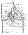
- tubular member 111 shown in FIG. 1 has a slightly different configuration from tubular member 111 shown in FIG. 3 in that in FIG.
- the fluid passageway or tube 93 has the same cross-sectional configuration throughout, whereby it is received into a matinq recess 113 formed at the top of tubular member 111 and is held in place in a conventional manner such as by gluing.
- the tubular member 111 of FIG. 3 is used with a fluid passageway, or tube, 93' which has an enlarged end portion 113, which in turn is connected to the recess 114 of.tubular member 111 in a conventional manner, such as by gluing.
- Piercing member 110 has an axial passageway 110' formed therein, and the end of this passageway 110' is provided with grooves 110'' to allow cleaning fluid to pass therethrough.
- cleaning fluid cartridge means 84 includes a flexible bag 115 and contains a suitable cleaning fluid (not shown) to be hereinafter described.
- Flexible bag 115 has an opening 116 therein, and a check valve or second check valve 98 is sealingly disposed within the opening 116.
- Flexible bag 115 may be manufactured of any suitable plastic material having the requisite strength characteristics and ability to withstand contact with the cleaning fluid. In this regard, a typical cleaning fluid useful for cleaning bathroom plumbing fixtures would contain phosphoric acid or other types of acid. Accordingly, flexible bag 115 should preferably be made of a material which is acid-resistant.
- Check valve 98 can be sealingly disposed within opening 116 of flexible bag 115 as by an acid resistant glue or the portion of flexible bag 115 at opening 116 may be heat sealed in any suitable manner to a lower outwardly extending circular flange member 117 formed on check valve 98.
- Cleaning fluid cartridge means 84 may further include a housing means 118 which surrounds and protects the flexible bag 115.
- housing means 118 includes a means for supporting 119 the check valve 98 within housing means 118.
- the means for supporting 119 comprises a circularly shaped internal flange 120 which is formed integral with the male threads 109 of cleaning fluid cartridge means 84.
- Check valve 98 has a second circular shaped outwardly extending flange member 121 which rests upon internal flange 120 which may be secured thereto in any suitable fashion, such as by gluing or heat sealing. Alternatively, check valve 98 may be supported within housing means 118 as by a snap-fit connection.
- check valve 98 has a general tubular configuration portion 98' having an inlet orifice 122, an exit orifice 123 and a sealing member chamber 124 having a sealing member 125 disposed within sealing member chamber 124.
- the inlet orifice 122 has a sealing surface 126 associated therewith which cooperates with the sealing member 125.
- sealing member 125 is a ball which is freely moveable within the sealing member chamber 124.
- the inlet orifice 122 has a reduced diameter portion 127.
- check valve 98 In manufacturing and filling cleaning fluid cartridge means 84, check valve 98 would be secured to the flexible bag 115 prior to check valve 98 being secured to housing means 118 as previously described. It would then be necessary to fill flexible bag 115 with the desired cleaning fluid.
- ball member 125 In the first method, ball member 125 is disposed within a reduced diameter portion 128 of exit orifice 123 as shown in dotted lines in FIG. 3, whereby the ball 125 is resiliently and sealingly secured therein. This resilient sealing engagement is obtained by having at least a portion of the check valve 98 formed of a resilient plastic material.
- ball member 125 can be made of a rigid material and the general tubular portion 98' of the check valve 98 can be made of a flexible plastic material.
- tubular configuration portion 98' of check valve 98 could be made of a rigid material and the ball member 125 could be made of a flexible material so as to be resiliently and sealingly secured within the reduced diameter portion 128 of exit orifice 123.
- the tubular configuration portion 98' of check valve 98 is made of a resilient plastic material and ball member 125 is made of a rigid material such as glass.
- exit orifice 123 of check valve 98 is sealed by ball member 125 in a sealed non-operating position.
- Flexible bag 115 may then be filled from its bottom 129 (FIG. 1) and bottom 129 may then be sealed in a suitable manner such as by gluing or heat sealing.
- Housing 118 may then be provided with a bottom member 118' which may be glued or heat sealed into place as shown in FIG. 1.
- flexible bag 115 is connected to check valve 98 and flexible bag 115 and check valve 98 are disposed within housing 118; however, ball member 125 is not inserted into the position shown in dotted lines in FIG. 3 until after flexible bag 115 has been filled with cleaning fluid through the completely opened check valve 98. After flexible bag 115 has been filled, ball member 125 may be forced into the exit orifice 123 into the sealed non-operating position shown in dotted lines in FIG. 3 whereby the cleaning fluid may be stored within the flexible bag 115. Additionally, a conventional bottle cap (not shown) may be threaded about the external threads 109 of housing means 118 to further prevent any leakage of the acidic cleaning fluid material contained within flexible bag 115.
- the second sealed operating position prevents egress of cleaning fluid through the valve.
- ball member 125 is shown in the second sealed operating position in that it is abutting the sealing surface 126 of inlet orifice 122.
- the first open operating position would occur when ball member 125 is spaced from the sealing surface 126 and is either freely supported within sealing member chamber 124, or is abutting the lower end of elongate piercing member 110.
- the movement of pump actuation means 87 determines which operating position ball member 125 assumes.
- second check valve 98 to be associated with handle 81 and not cleaning fluid cartridge means 84, it would be merely necessary to have some closure member at the top of flexible bag 115, which closure member would be pierced by elongate piercing member 110 so as to create a fluid passageway between flexible bag 115 and fluid passageway 93' via the axial passageway 110' of elongate piercing member 110.
- cleaning fluid may be discharged through the first end 82 of handle 81 and through the brush 105, whereby the surface to be cleaned may be scrubbed with brush 105.
- cleaning system 80 may be utilized to clean and scrub vertical surfaces or horizontal surfaces disposed above or below the operator of the system, and the desired cleaning fluid will be expelled from the cleaning system merely by depressing the moveable member, or trigger 89.
- cleaning system 80 should be utilized in a safe and proper manner and should not be aimed at anything but inanimate objects because of the potentially acidic nature of the cleaning fluid utilized therein.
- the cleaning fluid cartridge means 84 is mounted to the handle 81 with the outer upper surface 130 of the cleaning fluid cartridge means being substantially parallel and coplanar with the outer upper surface 131 of the handle 81. It has been found that this particular configuration enhances the ease with which the cleaning system 80 may be utilized by its operator, and constitutes an important feature of the present invention. Furthermore, the longitudinal axis of the cleaning fluid cartridge means 84 is disposed substantially parallel to the longitudinal axis of the handle 81 and the longitudinal axis of the cleaning fluid cartridge means is disposed substantially parallel to the lower outer surface 132 of the handle 81. This configuration likewise contributes to the enhanced ease of use of the cleaning system 80 of the present invention.
- the longitudinal axis of the first end 82 of the handle 81 is disposed at an acute angle to the longitudinal axis of the handle 81.
- Such acute angle varies whereby the first end 82 of handle 81 curves upwardly away from the upper surface 131 of the handle 81, whereby the surface cleaning means 85 likewise curves upwardly away from the upper surface of the handle.
- this configuration along with the design of the cleaning surface means 85, to be hereinafter described, readily lends itself to the cleaning of bathroom plumbing fixtures.
- the surface cleaning means 85 is a brush 105 having a central passageway 133 which resiliently engages the first end 82 of handle 81 as seen in FIG. 1.
- Passageway 133 has a wall surface 134 which includes means for allowing the brush 105 to conform to the outer configuration of the first end 82 of the handle 81.
- Such means for allowing the brush to conform as desired may preferably comprise a plurality of reduced diameter portions 135 formed on the exterior of passageway 133, which reduced diameter portions 135 allows the exterior wall surface of passageway 133 to flex.
- Brush 105 may preferably have a first set of bristles 136 forming the upper surface of the brush 105, with the ends of said bristles 136 forming a substantially horizontal planar scrubbing surface 137. Brush 105 may preferably further include a second set of bristles 138 forming the lower surface of the brush 105.
- the ends of said second set of'bristles 138 form a curved scrubbing surface 139 when viewed from the side as in FIG. 6 and from the end of the brush 105 as shown in FIG. 5.
- the first set of bristles 136 may be shorter in length than the second set of bristles 138 as seen in FIGS. 4-6.
- Brush 105 may further include a mirror 140 disposed on the horizontal planar scrubbing surface 137 which mirror 140 allows an operator to see a reflected view of the surface to be cleaned.
- a conventional bathroom commode, or water closet 141 is shown in FIG. 7. As is conventional with such commodes 141, there is normally an inwardly extending rim 142 which surrounds the bowl portion 143 of commode 141.
- surface cleaning means 85 or brush 105 includes an exit port 144 which is disposed between some of the bristles in the first set of bristles 136 whereby cleaning fluid may be expelled from the first end 82 of handle 81 which is in resilient engagement with the interior wall of passageway 133 of brush 105.
- curved surfaces 139 of brush 105 are particularly adapted for cleaning the drain exit 145 of commode 141 as well as the curved surfaces of bowl portion 143 of commode 141.
Landscapes
- Health & Medical Sciences (AREA)
- Public Health (AREA)
- Cleaning By Liquid Or Steam (AREA)
- Brushes (AREA)
- Bidet-Like Cleaning Device And Other Flush Toilet Accessories (AREA)
- Cleaning In General (AREA)
- Electrical Discharge Machining, Electrochemical Machining, And Combined Machining (AREA)
- Seal Device For Vehicle (AREA)
- Pharmaceuticals Containing Other Organic And Inorganic Compounds (AREA)
Priority Applications (1)
| Application Number | Priority Date | Filing Date | Title |
|---|---|---|---|
| AT84103248T ATE28554T1 (de) | 1983-03-24 | 1984-03-23 | Reinigungssystem. |
Applications Claiming Priority (2)
| Application Number | Priority Date | Filing Date | Title |
|---|---|---|---|
| US478516 | 1983-03-24 | ||
| US06/478,516 US4534669A (en) | 1983-03-24 | 1983-03-24 | Cleaning system with cartridge having valve means |
Publications (2)
| Publication Number | Publication Date |
|---|---|
| EP0123152A1 true EP0123152A1 (de) | 1984-10-31 |
| EP0123152B1 EP0123152B1 (de) | 1987-07-29 |
Family
ID=23900264
Family Applications (1)
| Application Number | Title | Priority Date | Filing Date |
|---|---|---|---|
| EP84103248A Expired EP0123152B1 (de) | 1983-03-24 | 1984-03-23 | Reinigungssystem |
Country Status (6)
| Country | Link |
|---|---|
| US (1) | US4534669A (de) |
| EP (1) | EP0123152B1 (de) |
| AT (1) | ATE28554T1 (de) |
| AU (1) | AU550087B2 (de) |
| CA (1) | CA1208859A (de) |
| DE (1) | DE3465008D1 (de) |
Cited By (3)
| Publication number | Priority date | Publication date | Assignee | Title |
|---|---|---|---|---|
| DE4106386A1 (de) * | 1990-03-02 | 1991-09-05 | Mitsubishi Pencil Co | Geraet zum auftragen von fluessigkeit |
| DE4106578A1 (de) * | 1990-03-02 | 1991-09-12 | Mitsubishi Pencil Co | Fluessigkeitsauftraeger |
| WO2003082048A1 (en) | 2002-04-03 | 2003-10-09 | Reckitt Benckiser (Uk) Limited | Cleaning apparatus and method for using the same |
Families Citing this family (22)
| Publication number | Priority date | Publication date | Assignee | Title |
|---|---|---|---|---|
| US4642836A (en) * | 1983-03-24 | 1987-02-17 | Sani-Fresh International, Inc. | Cleaning wand |
| US5622283A (en) * | 1995-01-31 | 1997-04-22 | The Testor Corporation | Paint dispensing system |
| US5865551A (en) * | 1996-06-10 | 1999-02-02 | New Knight Inc. | Cleaning device with replaceable cleaning fluid reservoir |
| USD383631S (en) * | 1996-06-21 | 1997-09-16 | Minnesota Mining & Manufacturing Company | Reservoir assembly for a product dispenser |
| USD386640S (en) * | 1996-06-21 | 1997-11-25 | Minnesota Mining And Manufacturing Company | Support and reservoir assembly for a product dispenser |
| US5799841A (en) * | 1996-06-21 | 1998-09-01 | Minnesota Mining And Manufacturing Company | Drip resistant nozzle for a dispenser |
| US5897031A (en) * | 1996-06-21 | 1999-04-27 | Minnesota Mining And Manufacturing Company | Dispenser for antimicrobial liquids |
| US6315481B1 (en) * | 1996-07-22 | 2001-11-13 | State Industrial Products | Self-contained cleaning system including integral bottle |
| USD418304S (en) * | 1998-08-10 | 2000-01-04 | Ekco Housewares, Inc. | Filled bowl brush with cleaner |
| WO2001065969A1 (en) * | 2000-03-09 | 2001-09-13 | Joachim Dettmann | Brush with means for dispensing cleaning liquid |
| US7048458B2 (en) * | 2000-03-24 | 2006-05-23 | The Clorox Company | Fluid valve and actuator for inverted fluid reservoir |
| US7004658B2 (en) * | 2000-03-24 | 2006-02-28 | The Clorox Company | Fluid valve and actuator for inverted fluid reservoir |
| DE20101077U1 (de) * | 2001-01-20 | 2002-05-23 | Naumann, Falk, Dipl.-Architekt, 06110 Halle | Reinigungshandgerät |
| WO2003073900A1 (en) * | 2002-03-06 | 2003-09-12 | Unilever Plc | Safety lockable household cleaning tool |
| US20050066996A1 (en) * | 2002-09-11 | 2005-03-31 | The Procter & Gamble Company | Stain-removal brush including cleaning composition dispenser |
| USD501606S1 (en) * | 2002-10-10 | 2005-02-08 | Reckitt Benckiser Inc. | Brush |
| US7467907B2 (en) * | 2003-08-19 | 2008-12-23 | Sanford, L.P. | Valve mechanisms for paint or ink brush with integrated reservoir |
| GB2412301A (en) | 2004-03-23 | 2005-09-28 | Reckitt Benckiser Inc | Cleaning device |
| DE202004019888U1 (de) * | 2004-12-20 | 2005-02-24 | Avet Ag | Reinigungsgerät |
| DE102004062336A1 (de) | 2004-12-20 | 2006-06-29 | Avet Ag | Reinigungsgerät |
| US20070071535A1 (en) * | 2005-09-26 | 2007-03-29 | Xg-3D | Cleaning apparatus and method of cleaning |
| KR200456236Y1 (ko) * | 2008-12-16 | 2011-10-20 | 주식회사 하나 | 액상 내용물 정량 배출 용기 |
Citations (5)
| Publication number | Priority date | Publication date | Assignee | Title |
|---|---|---|---|---|
| DE2040496A1 (de) * | 1970-08-14 | 1971-08-26 | Dietsche Roman Fa | Klosettbuerste,gegebenenfalls mit Spuelrandbuerste |
| DE2331694A1 (de) * | 1973-06-22 | 1975-01-16 | Alexander Ugrinsky | Reinigungsbuerste |
| DE2831205A1 (de) * | 1978-07-15 | 1980-01-24 | Henkel Kgaa | Toilettenbuerste |
| EP0014805A1 (de) * | 1979-02-07 | 1980-09-03 | Steiner Company International S.A. | System zum Ausgeben von Flüssigkeit |
| EP0052590A1 (de) * | 1980-11-12 | 1982-05-26 | Patara Ag | Vorrichtung zur dosierten Abgabe von Flüssigkeit aus einem Behälter |
Family Cites Families (7)
| Publication number | Priority date | Publication date | Assignee | Title |
|---|---|---|---|---|
| US2987743A (en) * | 1958-04-28 | 1961-06-13 | Richard D Martin | Toothbrush |
| US3228057A (en) * | 1964-03-09 | 1966-01-11 | Walter B Sprague | Combination applicator brush and dispenser |
| US3233594A (en) * | 1964-04-24 | 1966-02-08 | Sheaffer W A Pen Co | Fluid container |
| DE1291256B (de) * | 1967-03-25 | 1969-03-20 | Pelikan Werke Wagner Guenther | Fuellfederhalter mit einer Patronenaufnahme aus einem mittig angeordneten Nippel |
| US3788753A (en) * | 1973-03-19 | 1974-01-29 | S Stewart | Elongated liquid marker |
| US3877822A (en) * | 1973-10-23 | 1975-04-15 | Joanell Lab Inc | Fountain brush |
| US4217671A (en) * | 1979-01-25 | 1980-08-19 | Rand Bobby J | Multipurpose cleaning device |
-
1983
- 1983-03-24 US US06/478,516 patent/US4534669A/en not_active Expired - Fee Related
-
1984
- 1984-03-23 DE DE8484103248T patent/DE3465008D1/de not_active Expired
- 1984-03-23 CA CA000450433A patent/CA1208859A/en not_active Expired
- 1984-03-23 AT AT84103248T patent/ATE28554T1/de not_active IP Right Cessation
- 1984-03-23 EP EP84103248A patent/EP0123152B1/de not_active Expired
- 1984-03-26 AU AU26093/84A patent/AU550087B2/en not_active Ceased
Patent Citations (5)
| Publication number | Priority date | Publication date | Assignee | Title |
|---|---|---|---|---|
| DE2040496A1 (de) * | 1970-08-14 | 1971-08-26 | Dietsche Roman Fa | Klosettbuerste,gegebenenfalls mit Spuelrandbuerste |
| DE2331694A1 (de) * | 1973-06-22 | 1975-01-16 | Alexander Ugrinsky | Reinigungsbuerste |
| DE2831205A1 (de) * | 1978-07-15 | 1980-01-24 | Henkel Kgaa | Toilettenbuerste |
| EP0014805A1 (de) * | 1979-02-07 | 1980-09-03 | Steiner Company International S.A. | System zum Ausgeben von Flüssigkeit |
| EP0052590A1 (de) * | 1980-11-12 | 1982-05-26 | Patara Ag | Vorrichtung zur dosierten Abgabe von Flüssigkeit aus einem Behälter |
Cited By (4)
| Publication number | Priority date | Publication date | Assignee | Title |
|---|---|---|---|---|
| DE4106386A1 (de) * | 1990-03-02 | 1991-09-05 | Mitsubishi Pencil Co | Geraet zum auftragen von fluessigkeit |
| DE4106578A1 (de) * | 1990-03-02 | 1991-09-12 | Mitsubishi Pencil Co | Fluessigkeitsauftraeger |
| GB2242121A (en) * | 1990-03-02 | 1991-09-25 | Mitsubishi Pencil Co | Liquid applicator |
| WO2003082048A1 (en) | 2002-04-03 | 2003-10-09 | Reckitt Benckiser (Uk) Limited | Cleaning apparatus and method for using the same |
Also Published As
| Publication number | Publication date |
|---|---|
| DE3465008D1 (en) | 1987-09-03 |
| AU2609384A (en) | 1984-09-27 |
| CA1208859A (en) | 1986-08-05 |
| AU550087B2 (en) | 1986-02-27 |
| US4534669A (en) | 1985-08-13 |
| ATE28554T1 (de) | 1987-08-15 |
| EP0123152B1 (de) | 1987-07-29 |
Similar Documents
| Publication | Publication Date | Title |
|---|---|---|
| US4534669A (en) | Cleaning system with cartridge having valve means | |
| US7681765B2 (en) | Dispenser with draw-back mechanism | |
| CA2381868C (en) | Vacuum relief device | |
| EP2358605B1 (de) | Flüssigkeitsspender mit tropfstopp | |
| US5464125A (en) | Dispensing apparatus having a pump tube | |
| EP3648645A1 (de) | Nachfüllbare spender mit reservoirs und nachfüllbehältern für flüssigkeits- und lufttransfer zwischen diesen | |
| US20070157991A1 (en) | Dispensing apparatus and method | |
| US6618873B2 (en) | Automatic feed waste disposal tool | |
| US4640638A (en) | Cleaning system | |
| US20150108168A1 (en) | Dispenser for a pumpable fluid | |
| US4705420A (en) | Cleaning system having cleaning fluid capsule | |
| US11266279B2 (en) | Toilet seat sanitizer | |
| US4678105A (en) | Safety lock mechanism for cleaning wand | |
| EP0175505B1 (de) | Reinigungssystem mit zusammendrückbarem Einsatz | |
| GB2125462A (en) | Toilet bowl cleaning system | |
| KR200253066Y1 (ko) | 휴대용 위생 세정기 | |
| WO1995034503A1 (en) | Improved liquid dispenser | |
| JP3240884U (ja) | 液体ディスペンサー | |
| AU1861697A (en) | Cosmetic dispenser | |
| GB2366192A (en) | Cleaning fluid dispenser | |
| WO2005092146A1 (en) | Cleaning apparatus with interlock and lock-out feature |
Legal Events
| Date | Code | Title | Description |
|---|---|---|---|
| PUAI | Public reference made under article 153(3) epc to a published international application that has entered the european phase |
Free format text: ORIGINAL CODE: 0009012 |
|
| AK | Designated contracting states |
Designated state(s): AT BE DE FR GB IT NL |
|
| 17P | Request for examination filed |
Effective date: 19850422 |
|
| RAP1 | Party data changed (applicant data changed or rights of an application transferred) |
Owner name: SANI-FRESH INTERNATIONAL, INC. |
|
| 17Q | First examination report despatched |
Effective date: 19860407 |
|
| GRAA | (expected) grant |
Free format text: ORIGINAL CODE: 0009210 |
|
| AK | Designated contracting states |
Kind code of ref document: B1 Designated state(s): AT BE DE FR GB IT NL |
|
| REF | Corresponds to: |
Ref document number: 28554 Country of ref document: AT Date of ref document: 19870815 Kind code of ref document: T |
|
| ITF | It: translation for a ep patent filed | ||
| REF | Corresponds to: |
Ref document number: 3465008 Country of ref document: DE Date of ref document: 19870903 |
|
| ET | Fr: translation filed | ||
| PLBE | No opposition filed within time limit |
Free format text: ORIGINAL CODE: 0009261 |
|
| STAA | Information on the status of an ep patent application or granted ep patent |
Free format text: STATUS: NO OPPOSITION FILED WITHIN TIME LIMIT |
|
| 26N | No opposition filed | ||
| ITTA | It: last paid annual fee | ||
| PGFP | Annual fee paid to national office [announced via postgrant information from national office to epo] |
Ref country code: AT Payment date: 19960226 Year of fee payment: 13 |
|
| PG25 | Lapsed in a contracting state [announced via postgrant information from national office to epo] |
Ref country code: AT Effective date: 19970323 |
|
| PGFP | Annual fee paid to national office [announced via postgrant information from national office to epo] |
Ref country code: NL Payment date: 20001222 Year of fee payment: 18 |
|
| PGFP | Annual fee paid to national office [announced via postgrant information from national office to epo] |
Ref country code: GB Payment date: 20010202 Year of fee payment: 18 |
|
| PGFP | Annual fee paid to national office [announced via postgrant information from national office to epo] |
Ref country code: FR Payment date: 20010301 Year of fee payment: 18 |
|
| PGFP | Annual fee paid to national office [announced via postgrant information from national office to epo] |
Ref country code: DE Payment date: 20010330 Year of fee payment: 18 |
|
| REG | Reference to a national code |
Ref country code: GB Ref legal event code: IF02 |
|
| PG25 | Lapsed in a contracting state [announced via postgrant information from national office to epo] |
Ref country code: GB Free format text: LAPSE BECAUSE OF NON-PAYMENT OF DUE FEES Effective date: 20020323 |
|
| PGFP | Annual fee paid to national office [announced via postgrant information from national office to epo] |
Ref country code: BE Payment date: 20020416 Year of fee payment: 19 |
|
| PG25 | Lapsed in a contracting state [announced via postgrant information from national office to epo] |
Ref country code: NL Free format text: LAPSE BECAUSE OF NON-PAYMENT OF DUE FEES Effective date: 20021001 Ref country code: DE Free format text: LAPSE BECAUSE OF NON-PAYMENT OF DUE FEES Effective date: 20021001 |
|
| GBPC | Gb: european patent ceased through non-payment of renewal fee |
Effective date: 20020323 |
|
| PG25 | Lapsed in a contracting state [announced via postgrant information from national office to epo] |
Ref country code: FR Free format text: LAPSE BECAUSE OF NON-PAYMENT OF DUE FEES Effective date: 20021129 |
|
| NLV4 | Nl: lapsed or anulled due to non-payment of the annual fee |
Effective date: 20021001 |
|
| REG | Reference to a national code |
Ref country code: FR Ref legal event code: ST |
|
| PG25 | Lapsed in a contracting state [announced via postgrant information from national office to epo] |
Ref country code: BE Free format text: LAPSE BECAUSE OF NON-PAYMENT OF DUE FEES Effective date: 20030331 |
|
| BERE | Be: lapsed |
Owner name: *SANI-FRESH INTERNATIONAL INC. Effective date: 20030331 |