EP0123244A2 - Réfrigérateur à sublimation avec canal de ventilation refroidi par rayonnement - Google Patents
Réfrigérateur à sublimation avec canal de ventilation refroidi par rayonnement Download PDFInfo
- Publication number
- EP0123244A2 EP0123244A2 EP84104264A EP84104264A EP0123244A2 EP 0123244 A2 EP0123244 A2 EP 0123244A2 EP 84104264 A EP84104264 A EP 84104264A EP 84104264 A EP84104264 A EP 84104264A EP 0123244 A2 EP0123244 A2 EP 0123244A2
- Authority
- EP
- European Patent Office
- Prior art keywords
- cryogen
- cooler
- vent line
- vapor
- solid
- Prior art date
- Legal status (The legal status is an assumption and is not a legal conclusion. Google has not performed a legal analysis and makes no representation as to the accuracy of the status listed.)
- Granted
Links
- 239000007787 solid Substances 0.000 title claims abstract description 27
- 230000003071 parasitic effect Effects 0.000 claims abstract description 22
- VNWKTOKETHGBQD-UHFFFAOYSA-N methane Chemical compound C VNWKTOKETHGBQD-UHFFFAOYSA-N 0.000 claims description 36
- 238000013022 venting Methods 0.000 claims description 16
- 238000001816 cooling Methods 0.000 claims description 14
- 238000000034 method Methods 0.000 claims description 6
- 238000000859 sublimation Methods 0.000 claims description 4
- 230000008022 sublimation Effects 0.000 claims description 4
- 238000009413 insulation Methods 0.000 claims description 2
- 239000007769 metal material Substances 0.000 claims 2
- 238000010438 heat treatment Methods 0.000 claims 1
- 239000012774 insulation material Substances 0.000 claims 1
- 239000002826 coolant Substances 0.000 description 21
- IJGRMHOSHXDMSA-UHFFFAOYSA-N Atomic nitrogen Chemical compound N#N IJGRMHOSHXDMSA-UHFFFAOYSA-N 0.000 description 6
- 239000000463 material Substances 0.000 description 6
- UFHFLCQGNIYNRP-UHFFFAOYSA-N Hydrogen Chemical compound [H][H] UFHFLCQGNIYNRP-UHFFFAOYSA-N 0.000 description 5
- 239000001257 hydrogen Substances 0.000 description 5
- 229910052739 hydrogen Inorganic materials 0.000 description 5
- 239000007789 gas Substances 0.000 description 4
- 239000003507 refrigerant Substances 0.000 description 4
- 239000004593 Epoxy Substances 0.000 description 3
- 230000008901 benefit Effects 0.000 description 3
- 230000001419 dependent effect Effects 0.000 description 3
- 229910052757 nitrogen Inorganic materials 0.000 description 3
- 238000009428 plumbing Methods 0.000 description 3
- 230000009467 reduction Effects 0.000 description 3
- QGZKDVFQNNGYKY-UHFFFAOYSA-N Ammonia Chemical compound N QGZKDVFQNNGYKY-UHFFFAOYSA-N 0.000 description 2
- CURLTUGMZLYLDI-UHFFFAOYSA-N Carbon dioxide Chemical compound O=C=O CURLTUGMZLYLDI-UHFFFAOYSA-N 0.000 description 2
- 230000008859 change Effects 0.000 description 2
- 238000010276 construction Methods 0.000 description 2
- 230000007423 decrease Effects 0.000 description 2
- 230000000694 effects Effects 0.000 description 2
- 238000012986 modification Methods 0.000 description 2
- 230000004048 modification Effects 0.000 description 2
- 230000005855 radiation Effects 0.000 description 2
- 229920000134 Metallised film Polymers 0.000 description 1
- 239000004677 Nylon Substances 0.000 description 1
- HSFWRNGVRCDJHI-UHFFFAOYSA-N alpha-acetylene Natural products C#C HSFWRNGVRCDJHI-UHFFFAOYSA-N 0.000 description 1
- 229910052782 aluminium Inorganic materials 0.000 description 1
- XAGFODPZIPBFFR-UHFFFAOYSA-N aluminium Chemical compound [Al] XAGFODPZIPBFFR-UHFFFAOYSA-N 0.000 description 1
- 229910021529 ammonia Inorganic materials 0.000 description 1
- 229910002092 carbon dioxide Inorganic materials 0.000 description 1
- 239000001569 carbon dioxide Substances 0.000 description 1
- 239000004020 conductor Substances 0.000 description 1
- 230000001186 cumulative effect Effects 0.000 description 1
- 238000005516 engineering process Methods 0.000 description 1
- 125000002534 ethynyl group Chemical group [H]C#C* 0.000 description 1
- 239000011888 foil Substances 0.000 description 1
- 230000005484 gravity Effects 0.000 description 1
- 239000007788 liquid Substances 0.000 description 1
- 230000014759 maintenance of location Effects 0.000 description 1
- 229910052751 metal Inorganic materials 0.000 description 1
- 239000002184 metal Substances 0.000 description 1
- 229910052754 neon Inorganic materials 0.000 description 1
- GKAOGPIIYCISHV-UHFFFAOYSA-N neon atom Chemical compound [Ne] GKAOGPIIYCISHV-UHFFFAOYSA-N 0.000 description 1
- 229920001778 nylon Polymers 0.000 description 1
- 238000004513 sizing Methods 0.000 description 1
- 125000006850 spacer group Chemical group 0.000 description 1
- 238000005092 sublimation method Methods 0.000 description 1
- 238000002076 thermal analysis method Methods 0.000 description 1
- 238000012932 thermodynamic analysis Methods 0.000 description 1
- 230000007704 transition Effects 0.000 description 1
Images

Classifications
-
- F—MECHANICAL ENGINEERING; LIGHTING; HEATING; WEAPONS; BLASTING
- F25—REFRIGERATION OR COOLING; COMBINED HEATING AND REFRIGERATION SYSTEMS; HEAT PUMP SYSTEMS; MANUFACTURE OR STORAGE OF ICE; LIQUEFACTION SOLIDIFICATION OF GASES
- F25D—REFRIGERATORS; COLD ROOMS; ICE-BOXES; COOLING OR FREEZING APPARATUS NOT OTHERWISE PROVIDED FOR
- F25D3/00—Devices using other cold materials; Devices using cold-storage bodies
- F25D3/12—Devices using other cold materials; Devices using cold-storage bodies using solidified gases, e.g. carbon-dioxide snow
Definitions
- the present invention relates to solid subliming coolers and, more particularly, to a solid subliming cooler having a new radiatively-cooled vent line.
- Such coolers may be used, for example, in cryogenic coolant systems for space vehicles and/or other space borne apparatus.
- the vent line arrangement according to the invention radiates parasitic heat losses otherwise conducted through the vent line to the cryogen coolant and, by so doing, it permits the practical and thermally efficient use of cryogens (e.g. such as methane) at very low working temperatures which require corresponding extremely low operating vapor pressures.
- cryogens e.g. such as methane
- Such use of high heat capacity coolants at lower than usual operating temperatures results in substantial reductions in the required mass of cryogen for a given cooling mission and in overall cooler size and weight as compared to conventional cooling devices.
- Table 1 depicted below in Table 1 is a listing of the theoretical required weight and storage volume of four solid coolants for a five-year cooling load of 150 milliwatts at 50K (without yet taking into account parasitic heat losses). All such materials are candidates because the evolved vapor can be readily vented through plumbing while maintaining the desired temperature (i.e. the desired operating point on the temperature versus vapor pressure curves).
- the vapor pressure of the coolant must, of course, be sufficiently high to allow venting at the desired temperature through a reasonably-sized vent pipe. If the required vapor pressure is too low, the vent pipe must be so large in diameter that the conductive parasitic heat leak through the vent pipe itself becomes unacceptably high, and the total weight of the coolant needed to offset the leak as well as to cool the desired load may make the system impractical.
- the fifth entry in Table 1 (methane) would typically be eliminated as a practical coolant. That is, the vapor pressure of methane at 50K is only about 2 x 10- 3 Torr, thereby requiring an unacceptably large vent pipe. If methane could otherwise be used, it would result in the lightest total system because the cryogen tank volume would be relatively small and the empty tank mass would be lower than for a system utilizing hydrogen.
- a methane system would be superior to hydrogen in another important practical aspect. Hydrogen must be stored at a temperature far below the desired cooling temperature, (less than 14K) to maintain it in solid form for zero gravity coolant retention.
- a system utilizing the 56 pound hydrogen mass shown in Table 1 must take full advantage of the heat capacity of the gas between its subliming temperature of 10K and.the load temperature of 50K. The temperature rise contributes almost 50% of the available cooling capacity but it is not entirely useable.
- a "feedback" control loop and an active heater must be employed. This practical requirement reduces reliability and necessarily makes the above-noted 56 pound hydrogen mass only a minimum value. The prescribed mass could, in fact, nearly double depending on the variability of the thermal loads on the cooler.
- the present invention provides method and apparatus for lowering the useful operating temperature ranges of solid subliming coolers by utilizing cryogens in temperature ranges that heretofore were inaccessible or which presented impractical physical limitations on the cooling system.
- This object is achieved by using a radiatively-cooled vent arrangement which tends to radiate parasitic heat losses to space rather than permit them to be conducted through the walls of the vent line pipe itself into the cooler. This allows the use of cryogen coolants having significantly reduced overall mass and volume requirements.
- a horn-like, flared vent line structure (sometimes herein referred to as a "Flugelhorn") in a cooler arrangement which, in effect, combines features of a radiative cooler and a conventional solid subliming cryogen cooler.
- a radiatively-cooled vent structure allows a high heat capacity coolant (such as methane) to be used at subnormal operating temperatures, and results in a reduction in the overall size and weight of the cooler relative to conventional systems.
- methane and similar cryogens may be used in applications requiring very low vapor pressures by forming the vent line into variously shaped radiating structures (referred to herein as a "horn") whereby an aperture in the radiator is connected to a vent aperture in the solid cryogen container.
- the other end of the radiator aperture is vented and radiatively directed to outer (black) space.
- the diameter of the radiator aperture connected to the solid cryogen container can be maximized (i.e. sized as required to maintain the desired vapor pressure) since, for gaseous flow purposes, it acts essentially as an aperture in the container wall rather than as a long tube having substantial vapor flow resistance.
- the outer surface of the horn (the "inside" vent tube surface which is now flared and directed outwardly to space) is capable of radiating parasitic heat losses being conducted therealong that would otherwise be conducted along the vent tube walls to the cryogen container itself.
- the vent line according to the invention performs the same vapor venting function as would a large diameter vent line in a conventional solid subliming coolant system, but the thermal penalty otherwise resulting from the conduction of parasitic heat losses back to the cryogen cooler through the required large diameter vent line plumbing is substantially reduced.
- cryogens such as methane at low temperatures having inherently desirable low mass/volume characteristics are for the first time practical choices for many applications of this type of cooling system (e.g. a solid sublimation system where the working temperature is established by controlling the operating vapor pressure of the coolant material).
- this type of cooling system e.g. a solid sublimation system where the working temperature is established by controlling the operating vapor pressure of the coolant material.
- Prior practice limits the equilibrium pressure of solid subliming coolers to approximately 1 Torr.
- This invention extends the lower end of the pressure range to roughly 10 -4 Torr and extends the temperature range by a corresponding amount. This extension of temperature range frequently allows the use of a more mass efficient cryogen to meet the mission needs.
- FIGURE 1 a radiatively-cooled vent line in accordance with the present invention is shown generally at 10.
- a vent line arrangement for a 50K system (based on the amount of coolant required to absorb 150 milliwatts at 50K for 5 years) has been selected for illustration purposes only.
- a radiatively cooled vent line member (Flugelhorn) 11 may have a horn-like configuration with outwardly-flaring edges and as FIGURE 1 makes clear, the Flugelhorn may consist of an integral (one- piece) circularly symmetric construction having concentric openings at both ends. The smaller or bottom portion of the horn is attached (e.g.
- Vapor vent opening 13 thus permits a very low pressure high flow of vapor which is more typical of a mere aperture at 13 rather than the usual elongated tube vent line.
- Flugelhorn 11 may optionally be a thermal connection to a toroidal secondary cooler stage 30 of methane or other cryogen operating at about 75K (e.g. having a vapor pressure, for methane, of approximately 6 Torr vented conventionally through relatively small tubing 8) may be provided in thermal contact with the "inside" surfaces of the Flugelhorn via a thermally conducting ring 32.
- this secondary cooling stage may be provided by an auxiliary radiator external to the cooler. The temperature gradient through this portion of the horn is thus maintained so small that the parasitic heat leak (depicted as Q cl on Figure 1) is not a serious penalty on a 50K system.
- the location of the point of thermal contact with ring conductor 32 is chosen to minimize total coolant requirements in accordance with standard thermal analysis techniques. (Typically, it may be located about one-fourth to one-third of the way towards the higher temperature shell 21.) For many applications the secondary cooler 30 may not even be necessary nor desirable. In that event, the residual of parasitic heat flow Q c2 is dumped directly into the primary cooler 12 rather than secondary cooler 30.
- the horn flares to a large radiation surface (shown generally as 20) facing space and connects (e.g. a vacuum tight epoxy seal 7) at the periphery of its large diameter D 2 to vacuum shell 21 which may be radiatively cooled to a temperature of about 120°K.
- the radiant heat rejecting power Q r of this part of horn 11 to space is large enough to reduce the residual of the conductive parasitic heat flow (depicted as Q c2 ) which must be absorbed by the cryogen(s) to an acceptable level.
- the outer radiating surface is preferably of high emissivity to maximize its radiative properties, and is shaded from warm surfaces (e.g. sun, earth, spacecraft).
- the vacuum jacket 21 is cooled to roughly 120K by means of a conventional external radiator (not shown).
- the horn itself is preferably made of a low thermal conductivity material such as fiberglass-epoxy of minimum thickness for low lateral thermal conduction, and must typically structurally support one atmosphere of pressure with a safety factor for filling and ground operations.
- a foil metal liner (not shown) on the inside of vent horn 11 may be necessary to seal the horn against leakage into the high vacuum insulation space shown generally at 25 (e.g. multilayered aluminized Mylar and nylon net or other spacer material) surrounding the metallic (e.g. aluminum) container 12.
- An ejectable cover tank (not shown) containing liquid nitrogen (or other cryogen) may be used to reduce heat leakage for ground operations when the outer shell is at ambient temperature.
- the method for sizing the horn and estimating its thermal performance in the exemplary system is in accordance with conventional thermodynamic analysis and is outlined in general terms for the exemplary embodiment as follows.
- the diameter Dl and shape of the horn must be sized to cause less than about 2 x 10- 3 Torr pressure drop (space pressure can be assumed to be negligible) at the steady mass flow rate, M.
- This flow rate is based on the sum of the working heat load and all of the parasitic heat loads of the cooler.
- Li s is the latent heat of sublimation of the coolant.
- Conductance characteristics, or equations for the conductance through a vent line are conventionally expressed in terms of the gas properties, the geometry of the vent, and depend on the nature of the flow, i.e. whether it is laminar, free molecular or in the transition range between two flow regimes.
- a more complete discussion of vacuum conductance appears in "Cryogenic Systems” by Randall Barron, McGraw Hill, 1966 at page 540 and is incorporated herein by reference.
- the conductance increases as a function of the diameter to a power greater than two and decreases linearly with the length.
- the parasitic heat leak due to the horn is calculated using a network thermal model which takes into account all of the heat flow paths, material properties, geometry data and temperature profiles.
- the heat which reaches the 75K refrigerant (or the 50K refrigerant if a secondary cooler is not used) is greatly affected by the radiative power of the wide part of the horn and this fact is what makes the invention attractive and feasible.
- the lateral heat flow along the horn is determined by classical heat conduction equations of the general form: where K is the temperature dependent thermal conductivity of the material; A is the geometry- dependent cross-sectional area perpendicular to the heat flow; AT is the temperature difference over which the heat flow takes place, and L is the geometry- dependent length of the heat flow path.
- the radiant heat flow out of the horn is calculated by radiant heat transfer equations of the form: where ⁇ is the Stefan-Boltzmann constant; E is an overall emittance factor for the horn depending on the geometry and surface radiative properties; T h is the radiating surface temperature; A is the surface area of the horn facing space; T is the temperature of space, which can be assumed to be negligible for purposes of the present invention.
- nitrogen can be substituted for the less effective neon if the required temperature is near 30K; acetylene can be substituted for methane if the required temperature is near 90K; and ammonia can be substituted for carbon-dioxide at about 115K.
- Table II below lists cryogens whose minimum operating temperatures could be lowered by the Flugelhorn vent system in accordance with the present invention.
- Column 1 provides the expected minimum temperature utilizing conventional solid subliming cooler technology;
- Column 2 states the lowest temperatures achievable using radiatively-cooled vent line constructions in accordance with the present invention.
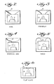
- vent horn 10 may be used for specific applications. Some of these are depicted in FIGURES 2-6.
- the cone-shaped horn of FIGURE 2 may well be the "best" configuration for many applications.
- the reversed spherical dish of FIGURE 4, the torroidal horn of FIGURE 5, the flat plate of FIGURE 6 and the parabolic horn of FIGURE 3 are other exemplary horn shapes.
Landscapes
- Engineering & Computer Science (AREA)
- Chemical & Material Sciences (AREA)
- Chemical Kinetics & Catalysis (AREA)
- Combustion & Propulsion (AREA)
- Physics & Mathematics (AREA)
- Mechanical Engineering (AREA)
- Thermal Sciences (AREA)
- General Engineering & Computer Science (AREA)
- Glass Compositions (AREA)
- Optical Couplings Of Light Guides (AREA)
- Semiconductor Lasers (AREA)
- Physical Or Chemical Processes And Apparatus (AREA)
Priority Applications (1)
| Application Number | Priority Date | Filing Date | Title |
|---|---|---|---|
| AT84104264T ATE31807T1 (de) | 1983-04-22 | 1984-04-14 | Sublimationskuehler mit strahlungsgekuehltem ventilierungskanal. |
Applications Claiming Priority (2)
| Application Number | Priority Date | Filing Date | Title |
|---|---|---|---|
| US487692 | 1983-04-22 | ||
| US06/487,692 US4507941A (en) | 1983-04-22 | 1983-04-22 | Solid subliming cooler with radiatively-cooled vent line |
Publications (3)
| Publication Number | Publication Date |
|---|---|
| EP0123244A2 true EP0123244A2 (fr) | 1984-10-31 |
| EP0123244A3 EP0123244A3 (en) | 1985-06-05 |
| EP0123244B1 EP0123244B1 (fr) | 1988-01-07 |
Family
ID=23936751
Family Applications (1)
| Application Number | Title | Priority Date | Filing Date |
|---|---|---|---|
| EP84104264A Expired EP0123244B1 (fr) | 1983-04-22 | 1984-04-14 | Réfrigérateur à sublimation avec canal de ventilation refroidi par rayonnement |
Country Status (5)
| Country | Link |
|---|---|
| US (1) | US4507941A (fr) |
| EP (1) | EP0123244B1 (fr) |
| JP (1) | JPS59200166A (fr) |
| AT (1) | ATE31807T1 (fr) |
| DE (1) | DE3468519D1 (fr) |
Families Citing this family (7)
| Publication number | Priority date | Publication date | Assignee | Title |
|---|---|---|---|---|
| DE3714424C1 (de) * | 1987-04-30 | 1988-06-09 | Messerschmitt Boelkow Blohm | Speicherung von Edelgas fuer elektrische Raumfahrtantriebe |
| FR2668069B1 (fr) * | 1990-10-18 | 1993-02-05 | Dassault Avions | Dispositif, notamment autonome et portable, pour extraire de la chaleur d'une source chaude. |
| US5241836A (en) * | 1993-01-25 | 1993-09-07 | The United States Of America As Represented By The Administrator Of The National Aeronautics And Space Administration | Patch for radiative coolers |
| US5419139A (en) * | 1993-12-13 | 1995-05-30 | Martin Marietta Corporation | Composite cryogenic tank apparatus |
| US5507146A (en) * | 1994-10-12 | 1996-04-16 | Consolidated Natural Gas Service Company, Inc. | Method and apparatus for condensing fugitive methane vapors |
| US5606870A (en) * | 1995-02-10 | 1997-03-04 | Redstone Engineering | Low-temperature refrigeration system with precise temperature control |
| US5697434A (en) * | 1995-09-20 | 1997-12-16 | Sun Microsystems, Inc. | Device having a reduced parasitic thermal load for terminating thermal conduit |
Family Cites Families (8)
| Publication number | Priority date | Publication date | Assignee | Title |
|---|---|---|---|---|
| US2512916A (en) * | 1943-04-09 | 1950-06-27 | L T Sepin | Method and apparatus for effecting expansion of gas |
| US2502588A (en) * | 1945-04-11 | 1950-04-04 | Linde Air Prod Co | Portable apparatus for holding and vaporizing liquefied gases |
| US3253423A (en) * | 1962-10-22 | 1966-05-31 | Philco Corp | Cryogenic cooling arrangement for space vehicles |
| US3422886A (en) * | 1966-07-25 | 1969-01-21 | Santa Barbara Res Center | Radiation cooler for use in space |
| FR1531804A (fr) * | 1967-07-06 | 1968-07-05 | Hughes Aircraft Co | Dispositif de refroidissement par rayonnement servant à maintenir un détecteur de rayonnement à une température cryogénique |
| US3545226A (en) * | 1969-01-17 | 1970-12-08 | Homer E Newell | Dual solid cryogens for spacecraft refrigeration |
| FR2268233B1 (fr) * | 1974-04-22 | 1977-10-21 | Commissariat Energie Atomique | |
| US4030316A (en) * | 1975-12-11 | 1977-06-21 | Rca Corporation | Passive cooler |
-
1983
- 1983-04-22 US US06/487,692 patent/US4507941A/en not_active Expired - Lifetime
-
1984
- 1984-04-14 EP EP84104264A patent/EP0123244B1/fr not_active Expired
- 1984-04-14 AT AT84104264T patent/ATE31807T1/de not_active IP Right Cessation
- 1984-04-14 DE DE8484104264T patent/DE3468519D1/de not_active Expired
- 1984-04-20 JP JP59078738A patent/JPS59200166A/ja active Pending
Also Published As
| Publication number | Publication date |
|---|---|
| JPS59200166A (ja) | 1984-11-13 |
| DE3468519D1 (en) | 1988-02-11 |
| EP0123244B1 (fr) | 1988-01-07 |
| ATE31807T1 (de) | 1988-01-15 |
| EP0123244A3 (en) | 1985-06-05 |
| US4507941A (en) | 1985-04-02 |
Similar Documents
| Publication | Publication Date | Title |
|---|---|---|
| US3133422A (en) | Insulation construction | |
| US20230060644A1 (en) | Temperature controlled payload container | |
| US4218892A (en) | Low cost cryostat | |
| US4821907A (en) | Surface tension confined liquid cryogen cooler | |
| CA1129793A (fr) | Recipient pour liquide cryogenique | |
| US8893514B2 (en) | Cryogenic liquid storage system for a spacecraft | |
| US3066222A (en) | Infra-red detection apparatus | |
| CA1132354A (fr) | Chambre frigorifique | |
| KR101046323B1 (ko) | 고온 초전도체 장치용 극저온 냉각 방법 및 장치 | |
| US3399691A (en) | Liquid transfer system | |
| Mardion et al. | Helium II in low-temperature and superconductive magnet engineering | |
| US3134237A (en) | Container for low-boiling liquefied gases | |
| EP0123244B1 (fr) | Réfrigérateur à sublimation avec canal de ventilation refroidi par rayonnement | |
| US8859153B1 (en) | Thermal conditioning fluids for an underwater cryogenic storage vessel | |
| US3724228A (en) | Composite insulation for cryogenic vessel | |
| Cunnington | Thermodynamic optimization of a cryogenic storage system for minimumboiloff | |
| US3646775A (en) | Cryostat | |
| Nast | Status of solid cryogen coolers | |
| US3436926A (en) | Refrigerating structure for cryostats | |
| Okamoto et al. | A low-loss, ultrahigh vacuum compatible helium cryostat without liquid nitrogen shield | |
| US4601175A (en) | Reduction of water condensation on neck tubes of cryogenic containers | |
| Mende et al. | Broad-neck liquid helium cryostat with a long lifetime | |
| Leupold et al. | Subcooled superfluid helium cryostat for a hybrid magnet system | |
| US3170306A (en) | Cryogenic means for cooling detectors | |
| Reynolds | Aircraft-fuel-tank design for liquid hydrogen |
Legal Events
| Date | Code | Title | Description |
|---|---|---|---|
| PUAI | Public reference made under article 153(3) epc to a published international application that has entered the european phase |
Free format text: ORIGINAL CODE: 0009012 |
|
| AK | Designated contracting states |
Designated state(s): AT BE CH DE FR GB IT LI LU NL SE |
|
| PUAL | Search report despatched |
Free format text: ORIGINAL CODE: 0009013 |
|
| AK | Designated contracting states |
Designated state(s): AT BE CH DE FR GB IT LI LU NL SE |
|
| 17P | Request for examination filed |
Effective date: 19851026 |
|
| 17Q | First examination report despatched |
Effective date: 19860505 |
|
| GRAA | (expected) grant |
Free format text: ORIGINAL CODE: 0009210 |
|
| AK | Designated contracting states |
Kind code of ref document: B1 Designated state(s): AT BE CH DE FR GB IT LI LU NL SE |
|
| PG25 | Lapsed in a contracting state [announced via postgrant information from national office to epo] |
Ref country code: AT Effective date: 19880107 |
|
| REF | Corresponds to: |
Ref document number: 31807 Country of ref document: AT Date of ref document: 19880115 Kind code of ref document: T |
|
| REF | Corresponds to: |
Ref document number: 3468519 Country of ref document: DE Date of ref document: 19880211 |
|
| ET | Fr: translation filed | ||
| ITF | It: translation for a ep patent filed | ||
| PG25 | Lapsed in a contracting state [announced via postgrant information from national office to epo] |
Ref country code: SE Effective date: 19880415 |
|
| PG25 | Lapsed in a contracting state [announced via postgrant information from national office to epo] |
Ref country code: LU Free format text: LAPSE BECAUSE OF NON-PAYMENT OF DUE FEES Effective date: 19880430 Ref country code: LI Effective date: 19880430 Ref country code: CH Effective date: 19880430 |
|
| BERE | Be: lapsed |
Owner name: BALL CORP. Effective date: 19880430 |
|
| PG25 | Lapsed in a contracting state [announced via postgrant information from national office to epo] |
Ref country code: NL Effective date: 19881101 |
|
| PLBE | No opposition filed within time limit |
Free format text: ORIGINAL CODE: 0009261 |
|
| STAA | Information on the status of an ep patent application or granted ep patent |
Free format text: STATUS: NO OPPOSITION FILED WITHIN TIME LIMIT |
|
| PG25 | Lapsed in a contracting state [announced via postgrant information from national office to epo] |
Ref country code: GB Effective date: 19881122 |
|
| NLV4 | Nl: lapsed or anulled due to non-payment of the annual fee | ||
| 26N | No opposition filed | ||
| GBPC | Gb: european patent ceased through non-payment of renewal fee | ||
| PG25 | Lapsed in a contracting state [announced via postgrant information from national office to epo] |
Ref country code: FR Free format text: LAPSE BECAUSE OF NON-PAYMENT OF DUE FEES Effective date: 19881229 |
|
| REG | Reference to a national code |
Ref country code: CH Ref legal event code: PL |
|
| PG25 | Lapsed in a contracting state [announced via postgrant information from national office to epo] |
Ref country code: DE Effective date: 19890103 |
|
| REG | Reference to a national code |
Ref country code: FR Ref legal event code: ST |
|
| PG25 | Lapsed in a contracting state [announced via postgrant information from national office to epo] |
Ref country code: BE Effective date: 19890430 |
|
| EUG | Se: european patent has lapsed |
Ref document number: 84104264.1 Effective date: 19890726 |