EP0123295A2 - Appareil de massage - Google Patents
Appareil de massage Download PDFInfo
- Publication number
- EP0123295A2 EP0123295A2 EP84104464A EP84104464A EP0123295A2 EP 0123295 A2 EP0123295 A2 EP 0123295A2 EP 84104464 A EP84104464 A EP 84104464A EP 84104464 A EP84104464 A EP 84104464A EP 0123295 A2 EP0123295 A2 EP 0123295A2
- Authority
- EP
- European Patent Office
- Prior art keywords
- housing
- massage device
- brush
- piston
- guide column
- Prior art date
- Legal status (The legal status is an assumption and is not a legal conclusion. Google has not performed a legal analysis and makes no representation as to the accuracy of the status listed.)
- Granted
Links
Images


Classifications
-
- A—HUMAN NECESSITIES
- A61—MEDICAL OR VETERINARY SCIENCE; HYGIENE
- A61H—PHYSICAL THERAPY APPARATUS, e.g. DEVICES FOR LOCATING OR STIMULATING REFLEX POINTS IN THE BODY; ARTIFICIAL RESPIRATION; MASSAGE; BATHING DEVICES FOR SPECIAL THERAPEUTIC OR HYGIENIC PURPOSES OR SPECIFIC PARTS OF THE BODY
- A61H7/00—Devices for suction-kneading massage; Devices for massaging the skin by rubbing or brushing not otherwise provided for
- A61H7/002—Devices for suction-kneading massage; Devices for massaging the skin by rubbing or brushing not otherwise provided for by rubbing or brushing
- A61H7/004—Devices for suction-kneading massage; Devices for massaging the skin by rubbing or brushing not otherwise provided for by rubbing or brushing power-driven, e.g. electrical
-
- A—HUMAN NECESSITIES
- A61—MEDICAL OR VETERINARY SCIENCE; HYGIENE
- A61H—PHYSICAL THERAPY APPARATUS, e.g. DEVICES FOR LOCATING OR STIMULATING REFLEX POINTS IN THE BODY; ARTIFICIAL RESPIRATION; MASSAGE; BATHING DEVICES FOR SPECIAL THERAPEUTIC OR HYGIENIC PURPOSES OR SPECIFIC PARTS OF THE BODY
- A61H2201/00—Characteristics of apparatus not provided for in the preceding codes
- A61H2201/12—Driving means
- A61H2201/1238—Driving means with hydraulic or pneumatic drive
- A61H2201/1246—Driving means with hydraulic or pneumatic drive by piston-cylinder systems
-
- A—HUMAN NECESSITIES
- A61—MEDICAL OR VETERINARY SCIENCE; HYGIENE
- A61H—PHYSICAL THERAPY APPARATUS, e.g. DEVICES FOR LOCATING OR STIMULATING REFLEX POINTS IN THE BODY; ARTIFICIAL RESPIRATION; MASSAGE; BATHING DEVICES FOR SPECIAL THERAPEUTIC OR HYGIENIC PURPOSES OR SPECIFIC PARTS OF THE BODY
- A61H2201/00—Characteristics of apparatus not provided for in the preceding codes
- A61H2201/14—Special force transmission means, i.e. between the driving means and the interface with the user
- A61H2201/1481—Special movement conversion means
- A61H2201/149—Special movement conversion means rotation-linear or vice versa
-
- A—HUMAN NECESSITIES
- A61—MEDICAL OR VETERINARY SCIENCE; HYGIENE
- A61H—PHYSICAL THERAPY APPARATUS, e.g. DEVICES FOR LOCATING OR STIMULATING REFLEX POINTS IN THE BODY; ARTIFICIAL RESPIRATION; MASSAGE; BATHING DEVICES FOR SPECIAL THERAPEUTIC OR HYGIENIC PURPOSES OR SPECIFIC PARTS OF THE BODY
- A61H2201/00—Characteristics of apparatus not provided for in the preceding codes
- A61H2201/16—Physical interface with patient
- A61H2201/1657—Movement of interface, i.e. force application means
- A61H2201/1664—Movement of interface, i.e. force application means linear
- A61H2201/1669—Movement of interface, i.e. force application means linear moving along the body in a reciprocating manner
-
- A—HUMAN NECESSITIES
- A61—MEDICAL OR VETERINARY SCIENCE; HYGIENE
- A61H—PHYSICAL THERAPY APPARATUS, e.g. DEVICES FOR LOCATING OR STIMULATING REFLEX POINTS IN THE BODY; ARTIFICIAL RESPIRATION; MASSAGE; BATHING DEVICES FOR SPECIAL THERAPEUTIC OR HYGIENIC PURPOSES OR SPECIFIC PARTS OF THE BODY
- A61H2201/00—Characteristics of apparatus not provided for in the preceding codes
- A61H2201/50—Control means thereof
- A61H2201/5051—Control means thereof hydraulically controlled
-
- Y—GENERAL TAGGING OF NEW TECHNOLOGICAL DEVELOPMENTS; GENERAL TAGGING OF CROSS-SECTIONAL TECHNOLOGIES SPANNING OVER SEVERAL SECTIONS OF THE IPC; TECHNICAL SUBJECTS COVERED BY FORMER USPC CROSS-REFERENCE ART COLLECTIONS [XRACs] AND DIGESTS
- Y10—TECHNICAL SUBJECTS COVERED BY FORMER USPC
- Y10T—TECHNICAL SUBJECTS COVERED BY FORMER US CLASSIFICATION
- Y10T74/00—Machine element or mechanism
- Y10T74/18—Mechanical movements
- Y10T74/18056—Rotary to or from reciprocating or oscillating
- Y10T74/18088—Rack and pinion type
- Y10T74/18104—Shiftable pinion
-
- Y—GENERAL TAGGING OF NEW TECHNOLOGICAL DEVELOPMENTS; GENERAL TAGGING OF CROSS-SECTIONAL TECHNOLOGIES SPANNING OVER SEVERAL SECTIONS OF THE IPC; TECHNICAL SUBJECTS COVERED BY FORMER USPC CROSS-REFERENCE ART COLLECTIONS [XRACs] AND DIGESTS
- Y10—TECHNICAL SUBJECTS COVERED BY FORMER USPC
- Y10T—TECHNICAL SUBJECTS COVERED BY FORMER US CLASSIFICATION
- Y10T74/00—Machine element or mechanism
- Y10T74/18—Mechanical movements
- Y10T74/18568—Reciprocating or oscillating to or from alternating rotary
- Y10T74/188—Reciprocating or oscillating to or from alternating rotary including spur gear
- Y10T74/18808—Reciprocating or oscillating to or from alternating rotary including spur gear with rack
Definitions
- the invention relates to a massage device with a rotating brush unit, which can be raised and lowered on a vertical guide column with the aid of a pressure-operated cylinder / piston unit and which can be set in rotation on a drive rail, the piston of the cylinder being released from the pressure medium by a control valve is alternately acted upon.
- Such a massage device in which a rotating roller or brush is arranged on a guide column designed as a square tube, the axis of which runs perpendicular to the guide column.
- the brush or roller is provided with a separate drive motor and is moved up and down by the cylinder / piston unit, the pressure-operated cylinder being connected to the water pipe.
- the cylinder can be acted on twice using a control valve.
- the main disadvantage of this known device is that only one brush is arranged, which must be provided with an additional drive motor.
- Another major disadvantage is that additional special fastening and mounting devices must be provided for the cylinder / piston unit. By arranging a single horizontal brush, a special massage effect cannot be achieved.
- the invention If the object of providing a massage device before strike, in which at achieving improved Mas - a robust drive of the brushes is guaranteed.
- piston arranged on a piston rod is fastened to a crossbar which is connected to the housing by means of connecting rods.
- An advantageous embodiment consists in that the piston is connected to the housing with the aid of a pulling cable which is guided over an upper and lower cable pulley, guide bands being arranged on both sides of the housing.
- stops for reversing the valve are provided on the crossbar and the housing.
- slots for the passage of the brushes are provided in a housing cover in accordance with the displacement path and the brush bodies are arranged in protective housings which have an extension guided in the slot.
- the guide column is arranged on a wall bracket so that it can be adjusted in height.
- a further advantageous embodiment consists in that a holder disk is attached to the brush drive shaft, onto which the brush body can be attached, the holder disk having a number of bores into which sleeves made of elastic material are inserted and that insertable into the sleeves on the back of the brush body Nipples are attached.
- the brush body has an annular bead which is inserted over the edge of the bracket disc.
- the mounting disk has a shaft hub, a corresponding recess being provided in the brush body.
- rods arranged in a hedgehog shape are attached to the brush body.
- the invention has the essential advantage that there is an automatically working, particularly stable and simple constructional massage device, whereby a particularly good massage effect is achieved by the two oppositely working brushes.
- the special design advantage also results from the fact that the piston / cylinder unit is centered by the brush unit itself in connection with the guide column. It is also essential that the rotating brushes meet certain requirements, since special forces and movements act on the brushes. The most varied designs required for such massage devices can be easily exchanged, and a stable holder is also guaranteed for operation.
- a white Another advantage of the arrangement of these brushes is that the manufacture can be achieved with simple shapes and means. The exchange takes place by simply pulling off the brush body and plugging in a new brush body, with no screwing work being necessary.
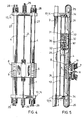
- the massager shown in Figures 1 to 3 has a vertically arranged guide column 1, preferably made of a square tube, this column l is suspended above and below with the help of clamping jaws 2 on a holder 3 which is attached to the wall.
- a guide column 1 To the side of the guide column 1 there are toothed racks 4, into which pinions 5 engage, on whose shafts 6 brushes 7 are arranged.
- the piston rod 9 of the cylinder / piston unit 10 with the piston lU ' has a crossbar 11 at its upper end, 11 connecting rods 12 being arranged on this crossbar and being fastened to the housing halves 8 at their opposite end. Furthermore, a mounting plate 13 is arranged both on the top and bottom of the guide column. There are also connection plates 14 for the pressure medium, a control valve 15 is attached to the upper plate 13, on which various connecting lines 16 are attached. Furthermore, the valve 15 is provided with switching pins 17 which cooperate with stops 18, a stop 18 being fastened to the housing 8 and a further stop 18 to the crossbar 11.
- the same parts are provided with the same reference numerals as in the embodiment according to FIGS. 1 to 3.
- the drive takes place of the housing 8 via a pull rope 24 which is attached to the piston 10 '.
- the traction cable 24 is guided via an upper pulley 25 to the housing 8 and on the other hand via a lower pulley 26 to the housing 8.
- the racks 4 attached to the front edge serve to guide the housing 8, with the fastening of the traction cable ends on the housing 8 in front of the racks 4.
- the traction cable ends are attached to the piston 10 'on a holding nipple 30 with an inserted screw connection 31, a trailing spring 32 being arranged between the holding nipple 30 and the screw connection 31.
- Seals 33 are provided for sealing the cable on the piston itself. Further seals 34 for the cable 24 when they are brought out of the cylinder 10 are provided on the upper and lower fastening plate 13.
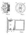
- the brush 7 runs in a protective housing 19, only the bristles of the brush 7 protruding, an attachment 20 being attached to the rear of this cover, which is in a housing cover 21 or a slot provided therein is guided.
- This protective housing can be designed as a type of shower, so that in addition to the actual massage effect by the brushes 7, a showering can also be carried out, wherein this protective housing 19 can be connected to the waste water line of the cylinder / piston unit 10, so that the water discharged thereby can be used sensibly.
- a further possibility is provided for fastening the device to the wall, a particularly tight attachment being thereby ensured by attaching a U-shaped holder 22 to the wall, which is provided with hooks 23 reaching inwards, which engages in the holder 2.
- the inlet to the cylinder / piston unit 10 As soon as the inlet to the cylinder / piston unit 10 is open for the pressure medium, it flows in from one side and moves the brush unit into one end position, the pressure medium flowing in from the other side by switching over at the valve 15 and the brush unit becoming itself moved in the opposite direction, the brushes 7 rotating against each other.
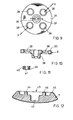
- the holding disk 35 shown in FIGS. 9 and 10 is attached with its centrally arranged hub 36 to a drive shaft 6. So that the disc 35 can be held against rotation on the shaft 6 is, for example as a transverse groove 37 which engages like a corresponding pin on the shaft 6. Furthermore, there are a number of bores 38 in the disk 35, which are narrowed in the middle, so that appropriately designed spouts 39, which are provided with grooves 40, are held. These grommets 39 are made of an elastic material, openings 41 being incorporated.
- Fig. 12 the brush body 7 is shown, which is adapted to the mounting plate 35, wherein a recess 42 is provided for receiving the hub 36. With the back 43 of this brush body 7 is then plugged onto the mounting plate 35, 39 nipples 44 being attached to the back of the brush body 7 according to the arrangement of the spouts, which can be inserted into the openings 41. Furthermore, the brush body 7 with its annular outer bead 45 is placed over the edge 46 of the mounting disk 35. The diameter of the nipples 44 is somewhat larger than the corresponding bores 41 in the spouts 39, so that a good mounting is ensured.
- FIG. 13 and 14 show the embodiment of a special massage brush, with bristles 47 arranged in an annular manner on the outside and rods 48 which are directed obliquely outwards and have thickenings 49 at their ends.
Landscapes
- Health & Medical Sciences (AREA)
- Dermatology (AREA)
- Epidemiology (AREA)
- Pain & Pain Management (AREA)
- Physical Education & Sports Medicine (AREA)
- Rehabilitation Therapy (AREA)
- Life Sciences & Earth Sciences (AREA)
- Animal Behavior & Ethology (AREA)
- General Health & Medical Sciences (AREA)
- Public Health (AREA)
- Veterinary Medicine (AREA)
- Massaging Devices (AREA)
Priority Applications (1)
| Application Number | Priority Date | Filing Date | Title |
|---|---|---|---|
| AT84104464T ATE35772T1 (de) | 1983-04-26 | 1984-04-19 | Massagegeraet. |
Applications Claiming Priority (4)
| Application Number | Priority Date | Filing Date | Title |
|---|---|---|---|
| DE19833315041 DE3315041C2 (de) | 1983-04-26 | 1983-04-26 | Massagegerät mit einem rotierenden Bürstenaggregat |
| DE3315041 | 1983-04-26 | ||
| DE8407237U | 1984-03-09 | ||
| DE19848407237 DE8407237U1 (de) | 1984-03-09 | 1984-03-09 | Buerstenhalterung mit buerste |
Publications (3)
| Publication Number | Publication Date |
|---|---|
| EP0123295A2 true EP0123295A2 (fr) | 1984-10-31 |
| EP0123295A3 EP0123295A3 (en) | 1985-10-30 |
| EP0123295B1 EP0123295B1 (fr) | 1988-07-20 |
Family
ID=25810315
Family Applications (1)
| Application Number | Title | Priority Date | Filing Date |
|---|---|---|---|
| EP84104464A Expired EP0123295B1 (fr) | 1983-04-26 | 1984-04-19 | Appareil de massage |
Country Status (7)
| Country | Link |
|---|---|
| US (1) | US4633857A (fr) |
| EP (1) | EP0123295B1 (fr) |
| CA (1) | CA1225297A (fr) |
| DE (1) | DE3472755D1 (fr) |
| ES (1) | ES279047Y (fr) |
| FI (1) | FI841510L (fr) |
| NO (1) | NO156356C (fr) |
Cited By (7)
| Publication number | Priority date | Publication date | Assignee | Title |
|---|---|---|---|---|
| EP0296128A3 (fr) * | 1987-06-12 | 1990-02-07 | Giovanni Bettuzzi | Appareil de massage corporel |
| WO1994018929A1 (fr) * | 1993-02-27 | 1994-09-01 | Stahl Karl Martin | Dispositif de lavage corporel, soins corporels, ainsi que de massage medical et de traitement dans des bains et douches |
| DE4429220A1 (de) * | 1994-08-18 | 1996-07-04 | Rational Beratungsgesellschaft | Massage- und Bürstgerät |
| DE102007023604A1 (de) | 2007-05-21 | 2008-11-27 | Mennenga, Heyo, Dr.-Ing. | Vorrichtung zum Reinigen und Massieren des Rückens |
| FR2951074A1 (fr) * | 2009-10-09 | 2011-04-15 | Jean Garcia | Dispositif de massage du dos |
| DE102019003397B3 (de) | 2019-05-14 | 2020-07-16 | Bernd Jablonowski | Massagegerät zur Massage von Händen und Füßen |
| DE102019124996A1 (de) * | 2019-09-17 | 2021-03-18 | Heinrich Schwörer | Massagevorrichtung |
Families Citing this family (7)
| Publication number | Priority date | Publication date | Assignee | Title |
|---|---|---|---|---|
| US4817227A (en) * | 1987-06-11 | 1989-04-04 | Scott John H | Body scrubber |
| US5065743A (en) * | 1988-06-20 | 1991-11-19 | Sutherland W Don | Kneader |
| US4955101A (en) * | 1989-07-18 | 1990-09-11 | Hope Technologies Corp. | Body scrubbing brush apparatus |
| US6174296B1 (en) * | 1999-06-14 | 2001-01-16 | Ming-Cheng Wang | Automatic back rubbing assembly |
| GB201101872D0 (en) * | 2011-02-03 | 2011-03-23 | Majeed Ali W | Instrument cleaning assembly and apparatus |
| US9204706B1 (en) | 2013-10-03 | 2015-12-08 | Shane R. Applebee | Disposable body lotion applicator |
| CN104259740A (zh) * | 2014-09-12 | 2015-01-07 | 苏州石丸英合精密机械有限公司 | 电机转子自动装配机的回转机械手升降装置 |
Family Cites Families (20)
| Publication number | Priority date | Publication date | Assignee | Title |
|---|---|---|---|---|
| US1323057A (en) * | 1919-11-25 | Tooth-brush | ||
| GB240838A (fr) * | ||||
| DE463567C (de) * | 1928-07-31 | Kurt Stohmann | Geraet zum Reinigen von Zahnbohrern | |
| US921991A (en) * | 1908-11-16 | 1909-05-18 | Thomas Hubert Hood | Mixer. |
| US1220862A (en) * | 1916-06-02 | 1917-03-27 | Samuel W Lewis | Agitating device. |
| US1577751A (en) * | 1921-08-09 | 1926-03-23 | Paschall Benjamin Stuart | Mechanism for massaging |
| FR1228374A (fr) * | 1958-03-21 | 1960-08-29 | Bendix Aviat Corp | Machine alternative à engrenage utilisable notamment comme vérin pneumatique ou hydraulique |
| US3085269A (en) * | 1962-08-02 | 1963-04-16 | Greer Robert | Rotary shower brush |
| US3415131A (en) * | 1967-03-09 | 1968-12-10 | Harold C. Zieber | Driving mechanism |
| US3768462A (en) * | 1972-03-24 | 1973-10-30 | L Boulard | Scrubbing and massaging apparatus |
| DE2429808A1 (de) * | 1974-06-21 | 1976-01-15 | Karl Heinz Paul Petry | Massagegeraet |
| SU631145A1 (ru) * | 1974-09-19 | 1978-11-05 | Bogatyrev Viktor A | Устройство дл мыть и чистки поверхностей |
| US4155137A (en) * | 1977-08-29 | 1979-05-22 | Kadlub Thomas E | Water powered brush method and apparatus |
| IT1103427B (it) * | 1978-05-19 | 1985-10-14 | Vivo Alessandro | Apparecchio applicabile in un loca da bagno per agevolare il lavaggio a persona con l ausilio di mezzi a spazzola ruotante e mobile alternativamente |
| US4356583A (en) * | 1981-03-12 | 1982-11-02 | Lutz Wallasch | Liquid-operated reciprocating prime mover assembly and body washing apparatus incorporating same |
| EP0091032B1 (fr) * | 1982-04-02 | 1986-09-10 | Heinz Georg Baus | Douche de massage |
| JPS58182234A (ja) * | 1982-04-17 | 1983-10-25 | Dainippon Screen Mfg Co Ltd | 複数種のブラシ使用可能な洗浄装置 |
| BE893388A (nl) * | 1982-06-02 | 1982-10-01 | Steeman Gilbert | Automatisch rugwasapparaat |
| DE3303925C2 (de) * | 1983-02-05 | 1985-03-07 | Heinz Georg Hünibach Thun Baus | Massageeinrichtung |
| US4490871A (en) * | 1983-09-01 | 1985-01-01 | Martin Paul H | Reciprocating rotary brush |
-
1984
- 1984-04-16 FI FI841510A patent/FI841510L/fi not_active Application Discontinuation
- 1984-04-19 DE DE8484104464T patent/DE3472755D1/de not_active Expired
- 1984-04-19 EP EP84104464A patent/EP0123295B1/fr not_active Expired
- 1984-04-25 NO NO841625A patent/NO156356C/no unknown
- 1984-04-26 CA CA000452800A patent/CA1225297A/fr not_active Expired
- 1984-04-26 ES ES1984279047U patent/ES279047Y/es not_active Expired
- 1984-04-27 US US06/604,639 patent/US4633857A/en not_active Expired - Fee Related
Cited By (8)
| Publication number | Priority date | Publication date | Assignee | Title |
|---|---|---|---|---|
| EP0296128A3 (fr) * | 1987-06-12 | 1990-02-07 | Giovanni Bettuzzi | Appareil de massage corporel |
| WO1994018929A1 (fr) * | 1993-02-27 | 1994-09-01 | Stahl Karl Martin | Dispositif de lavage corporel, soins corporels, ainsi que de massage medical et de traitement dans des bains et douches |
| DE4429220A1 (de) * | 1994-08-18 | 1996-07-04 | Rational Beratungsgesellschaft | Massage- und Bürstgerät |
| DE102007023604A1 (de) | 2007-05-21 | 2008-11-27 | Mennenga, Heyo, Dr.-Ing. | Vorrichtung zum Reinigen und Massieren des Rückens |
| FR2951074A1 (fr) * | 2009-10-09 | 2011-04-15 | Jean Garcia | Dispositif de massage du dos |
| DE102019003397B3 (de) | 2019-05-14 | 2020-07-16 | Bernd Jablonowski | Massagegerät zur Massage von Händen und Füßen |
| WO2020228876A1 (fr) | 2019-05-14 | 2020-11-19 | Bernd Jablonowski | Appareil de massage |
| DE102019124996A1 (de) * | 2019-09-17 | 2021-03-18 | Heinrich Schwörer | Massagevorrichtung |
Also Published As
| Publication number | Publication date |
|---|---|
| CA1225297A (fr) | 1987-08-11 |
| DE3472755D1 (en) | 1988-08-25 |
| NO841625L (no) | 1984-10-29 |
| EP0123295A3 (en) | 1985-10-30 |
| ES279047U (es) | 1985-04-01 |
| NO156356C (no) | 1987-09-09 |
| FI841510A0 (fi) | 1984-04-16 |
| FI841510A7 (fi) | 1984-10-27 |
| EP0123295B1 (fr) | 1988-07-20 |
| ES279047Y (es) | 1985-11-01 |
| FI841510L (fi) | 1984-10-27 |
| NO156356B (no) | 1987-06-01 |
| US4633857A (en) | 1987-01-06 |
Similar Documents
| Publication | Publication Date | Title |
|---|---|---|
| DE1966202C3 (de) | Schleuderstrahlmaschine | |
| EP0123295A2 (fr) | Appareil de massage | |
| CH643725A5 (de) | Massagedusche mit einer fuehrungsschiene. | |
| DE2222198A1 (de) | Haftstrang-Austragsvorrichtung | |
| DE1759861C3 (de) | Biologische Abwasserreinigungsanlage | |
| DE3447978A1 (de) | Reinigungsvorrichtung fuer eine filterpresse | |
| DE1553229A1 (de) | Pumpe mit zusammendrueckbaren Roehren | |
| DE2045541A1 (de) | Waschvorrichtung | |
| DE2306462B2 (de) | Rohrverbindung für Doppelrohrstränge | |
| DE3010029C2 (de) | Fahnenmast mit Hißvorrichtung | |
| DE4105528C2 (fr) | ||
| DE4441637C2 (de) | Schuhsohlen-Reinigungsmaschine | |
| AT396800B (de) | Einrichtung zur beseitigung von verstopfungen in abflussrohren | |
| DE3315041C2 (de) | Massagegerät mit einem rotierenden Bürstenaggregat | |
| DE3853823T2 (de) | Umwandler für eine drehbewegung in eine hin- und hergehende bewegung und umgekehrt. | |
| DE19523621C2 (de) | Vorrichtung zum Behandeln, Färben, Appretieren, Waschen o. dgl. von laufenden, schmalen textilen Bändern | |
| DE2229004C3 (de) | Schmiermittel-Reinigungsfilter | |
| DE69903007T2 (de) | Untertischkreissäge | |
| DE2559494A1 (de) | Farbbandkassette fuer schreib- und aehnliche maschinen | |
| DE2507303A1 (de) | Von einem steuerbaren motor antreibbares getriebe | |
| DE8309061U1 (de) | Vorrichtung zum transportieren von gegenstaenden bzw. zum selbstfortbewegen | |
| DE1406913C (de) | Antrieb fur Dungfordervorrichtung mit hin und hergehender Triebstange | |
| DE3042443A1 (de) | Vorrichtung zur reinigung von wasser- und abwasserrechen | |
| DE825360C (de) | Vorrichtung zur mechanischen Reinigung von Fahrzeugen | |
| AT236060B (de) | Einrichtung zum Öffnen und Schließen von Vorhängen |
Legal Events
| Date | Code | Title | Description |
|---|---|---|---|
| PUAI | Public reference made under article 153(3) epc to a published international application that has entered the european phase |
Free format text: ORIGINAL CODE: 0009012 |
|
| AK | Designated contracting states |
Designated state(s): AT BE CH DE FR GB IT LI LU NL SE |
|
| PUAL | Search report despatched |
Free format text: ORIGINAL CODE: 0009013 |
|
| AK | Designated contracting states |
Designated state(s): AT BE CH DE FR GB IT LI LU NL SE |
|
| 17P | Request for examination filed |
Effective date: 19850918 |
|
| 17Q | First examination report despatched |
Effective date: 19861105 |
|
| GRAA | (expected) grant |
Free format text: ORIGINAL CODE: 0009210 |
|
| AK | Designated contracting states |
Kind code of ref document: B1 Designated state(s): AT BE CH DE FR GB IT LI LU NL SE |
|
| PG25 | Lapsed in a contracting state [announced via postgrant information from national office to epo] |
Ref country code: SE Effective date: 19880720 Ref country code: NL Effective date: 19880720 Ref country code: IT Free format text: LAPSE BECAUSE OF FAILURE TO SUBMIT A TRANSLATION OF THE DESCRIPTION OR TO PAY THE FEE WITHIN THE PRESCRIBED TIME-LIMIT;WARNING: LAPSES OF ITALIAN PATENTS WITH EFFECTIVE DATE BEFORE 2007 MAY HAVE OCCURRED AT ANY TIME BEFORE 2007. THE CORRECT EFFECTIVE DATE MAY BE DIFFERENT FROM THE ONE RECORDED. Effective date: 19880720 Ref country code: GB Free format text: LAPSE BECAUSE OF NON-PAYMENT OF DUE FEES Effective date: 19880720 Ref country code: FR Free format text: THE PATENT HAS BEEN ANNULLED BY A DECISION OF A NATIONAL AUTHORITY Effective date: 19880720 Ref country code: BE Effective date: 19880720 |
|
| REF | Corresponds to: |
Ref document number: 35772 Country of ref document: AT Date of ref document: 19880815 Kind code of ref document: T |
|
| REF | Corresponds to: |
Ref document number: 3472755 Country of ref document: DE Date of ref document: 19880825 |
|
| EN | Fr: translation not filed | ||
| NLV1 | Nl: lapsed or annulled due to failure to fulfill the requirements of art. 29p and 29m of the patents act | ||
| GBV | Gb: ep patent (uk) treated as always having been void in accordance with gb section 77(7)/1977 [no translation filed] | ||
| PG25 | Lapsed in a contracting state [announced via postgrant information from national office to epo] |
Ref country code: AT Effective date: 19890419 |
|
| PG25 | Lapsed in a contracting state [announced via postgrant information from national office to epo] |
Ref country code: LU Free format text: LAPSE BECAUSE OF NON-PAYMENT OF DUE FEES Effective date: 19890430 Ref country code: LI Effective date: 19890430 Ref country code: CH Effective date: 19890430 |
|
| PLBE | No opposition filed within time limit |
Free format text: ORIGINAL CODE: 0009261 |
|
| STAA | Information on the status of an ep patent application or granted ep patent |
Free format text: STATUS: NO OPPOSITION FILED WITHIN TIME LIMIT |
|
| 26N | No opposition filed | ||
| REG | Reference to a national code |
Ref country code: CH Ref legal event code: PL |
|
| PG25 | Lapsed in a contracting state [announced via postgrant information from national office to epo] |
Ref country code: DE Effective date: 19900103 |