EP0123305A2 - Einrichtung zur Registerregelung für Druckmaschinen - Google Patents
Einrichtung zur Registerregelung für Druckmaschinen Download PDFInfo
- Publication number
- EP0123305A2 EP0123305A2 EP84104516A EP84104516A EP0123305A2 EP 0123305 A2 EP0123305 A2 EP 0123305A2 EP 84104516 A EP84104516 A EP 84104516A EP 84104516 A EP84104516 A EP 84104516A EP 0123305 A2 EP0123305 A2 EP 0123305A2
- Authority
- EP
- European Patent Office
- Prior art keywords
- register
- printing unit
- control system
- optical scanner
- printing
- Prior art date
- Legal status (The legal status is an assumption and is not a legal conclusion. Google has not performed a legal analysis and makes no representation as to the accuracy of the status listed.)
- Withdrawn
Links
- 238000007639 printing Methods 0.000 title claims description 77
- 230000003287 optical effect Effects 0.000 claims abstract description 41
- 230000004044 response Effects 0.000 claims description 7
- 238000012935 Averaging Methods 0.000 claims description 5
- 238000001514 detection method Methods 0.000 claims description 2
- 230000002401 inhibitory effect Effects 0.000 claims 1
- 238000000034 method Methods 0.000 description 51
- 230000008569 process Effects 0.000 description 49
- 238000012937 correction Methods 0.000 description 17
- 101100443251 Saccharomyces cerevisiae (strain ATCC 204508 / S288c) DIG2 gene Proteins 0.000 description 13
- 101100041128 Schizosaccharomyces pombe (strain 972 / ATCC 24843) rst2 gene Proteins 0.000 description 13
- 101100041125 Arabidopsis thaliana RST1 gene Proteins 0.000 description 11
- 101100443250 Saccharomyces cerevisiae (strain ATCC 204508 / S288c) DIG1 gene Proteins 0.000 description 11
- 238000013480 data collection Methods 0.000 description 9
- 230000033001 locomotion Effects 0.000 description 8
- 230000006870 function Effects 0.000 description 7
- 239000003086 colorant Substances 0.000 description 6
- 239000011159 matrix material Substances 0.000 description 5
- 239000000976 ink Substances 0.000 description 4
- 238000012545 processing Methods 0.000 description 4
- 102100040862 Dual specificity protein kinase CLK1 Human genes 0.000 description 3
- 102100040844 Dual specificity protein kinase CLK2 Human genes 0.000 description 3
- 101000749291 Homo sapiens Dual specificity protein kinase CLK2 Proteins 0.000 description 3
- 238000004458 analytical method Methods 0.000 description 3
- 238000010586 diagram Methods 0.000 description 3
- 239000000463 material Substances 0.000 description 3
- 238000005259 measurement Methods 0.000 description 3
- 238000002360 preparation method Methods 0.000 description 3
- 101000749294 Homo sapiens Dual specificity protein kinase CLK1 Proteins 0.000 description 2
- 101710092886 Integrator complex subunit 3 Proteins 0.000 description 2
- 102100030147 Integrator complex subunit 7 Human genes 0.000 description 2
- 101710092890 Integrator complex subunit 7 Proteins 0.000 description 2
- 102100025254 Neurogenic locus notch homolog protein 4 Human genes 0.000 description 2
- 238000004737 colorimetric analysis Methods 0.000 description 2
- 230000000881 depressing effect Effects 0.000 description 2
- 238000009434 installation Methods 0.000 description 2
- 238000001459 lithography Methods 0.000 description 2
- 238000007645 offset printing Methods 0.000 description 2
- 238000012360 testing method Methods 0.000 description 2
- 230000005540 biological transmission Effects 0.000 description 1
- 230000015572 biosynthetic process Effects 0.000 description 1
- 239000000872 buffer Substances 0.000 description 1
- 230000008859 change Effects 0.000 description 1
- HPNSNYBUADCFDR-UHFFFAOYSA-N chromafenozide Chemical compound CC1=CC(C)=CC(C(=O)N(NC(=O)C=2C(=C3CCCOC3=CC=2)C)C(C)(C)C)=C1 HPNSNYBUADCFDR-UHFFFAOYSA-N 0.000 description 1
- 239000011248 coating agent Substances 0.000 description 1
- 238000000576 coating method Methods 0.000 description 1
- 238000007405 data analysis Methods 0.000 description 1
- 230000003111 delayed effect Effects 0.000 description 1
- 238000007646 gravure printing Methods 0.000 description 1
- 230000036039 immunity Effects 0.000 description 1
- 230000002452 interceptive effect Effects 0.000 description 1
- 230000007774 longterm Effects 0.000 description 1
- 238000012423 maintenance Methods 0.000 description 1
- 238000012856 packing Methods 0.000 description 1
- 230000000737 periodic effect Effects 0.000 description 1
- 230000002441 reversible effect Effects 0.000 description 1
- 238000013519 translation Methods 0.000 description 1
- 239000013598 vector Substances 0.000 description 1
Images






Classifications
-
- B—PERFORMING OPERATIONS; TRANSPORTING
- B41—PRINTING; LINING MACHINES; TYPEWRITERS; STAMPS
- B41F—PRINTING MACHINES OR PRESSES
- B41F13/00—Common details of rotary presses or machines
- B41F13/02—Conveying or guiding webs through presses or machines
- B41F13/025—Registering devices
Definitions
- the field of the invention is control systems for adjusting the color-to-color register on web offset presses, gravure presses and flexographic presses.
- a web of material to be printed is driven through a series of cylinders which separately print an image on the web using inks of selected colors.
- the rotational and lateral position of each print cylinder is precisely aligned such that the register of the separate colors is maintained to provide an accurate and clear print image.
- register control systems Numerous types of register control systems are employed in the art to maintain color-to-color register under a variety of operating conditions. These control systems are in most cases open loop systems in which an operator periodically examines the print image and manually enters correction values to adjust the lateral or rotational alignments of one or more print cylinders.
- Closed loop register control systems have been employed on gravure printing presses.
- a series of register marks is printed by each print cylinder and an optical detector is positioned after each print cylinder to detect these marks.
- the timing of the electrical pulses produced by the optical detector and the duration of each pulse provide position feedback information indicative of the rotational and lateral alignment of the print cylinder with respect to the framework of the press. This position feedback information is employed to automatically adjust the register of the print cylinder with respect to the press framework.
- the present invention relates to a closed loop register control system in which a single optical scanner is employed to provide position feedback information that indicates the relative register of each print cylinder with respect to a designated reference print cylinder.
- Each print cylinder produces a specific register mark which forms part of a register pattern.
- the feedback signal produced by the optical scanner as it reads the register pattern is analyzed to determine the lateral and rotational register of each print cylinder with respect to the reference print cylinder.
- Register error signals are thus produced for each print cylinder and are employed to control motors that adjust the position of each.
- a general object of the invention is to provide a closed loop register control system for an offset printing press.
- a single optical scanner may be employed and it is positioned at the output of the press where the moving web can be properly constrained to allow accurate detection of the register pattern.
- Another object of the invention is to provide an accurate register control system. By measuring the relative register of each print cylinder with respect to the reference print cylinder rather than a timing signal related to press position, mechanical inaccuracies in the press gear train are eliminated. i
- Yet another object of the invention is to provide an accurate indication of register error which is not subject to spurious deviations.
- Each signature which is output by the press contains a register pattern and thus discrete position feedback signals are generated at a high rate.
- Spurious position feedback signals are eliminated in a first analysis which rejects position feedback signals that indicate extraordinary register errors.
- the position error signal used for control purposes is obtained by averaging a series of acceptable readings.
- a more specific object of the invention is to enable the register control system to be easily configured to any press.
- the set-up procedure is an interactive process in which the operator is prompted to enter the required data.
- Such data includes offset data for each color print cylinder to account for printing errors in the register pattern.
- the print cylinder which is to be used as the reference color is also identified during set-up.
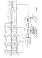
- the present invention is applied to a web offset printing press 1 which includes four blanket-to-blanket printing units 2 to 5.
- a web 6 is fed through the successive printing units 2 to 5 from a reel stand (not shown in the drawings) and it is then fed through a dryer unit 7 and a chill unit 8.
- the printed web 6 may then be guided through coating equipment (not shown) and folding equipment (not shown) which fold and separate the web into individual signatures.
- Each printing unit 2 to 5 includes an upper printing couple comprised of an upper blanket cylinder 10 and upper plate cylinder 11, and a lower printing couple comprised of a lower blanket cylinder 12 and lower plate cylinder 13.
- the printing unit 2 prints the color black on the top and bottom surfaces of the web 6, and subsequent printing units 3 to 5 print other colors on both surfaces of the web 6.
- Both the lateral and rotational position of the upper plate cylinders 11 and lower plate cylinders 13 are separately controlled by electric motors to precisely register the separate color images.
- the present invention is a register control system which automatically controls the register of the four printing units 2 to 5. It will become evident that while a four unit, single web, offset lithography printing press is shown and described in this specification, that the present invention is applicable to other presses.
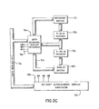
- the register control system includes a centrally located system processor 15 which is operated from a main control panel 16. Information regarding the register of the four printing units 2 to 5 is received by the system processor 15 from a scanner interface 17, which in turn connects to a pair of optical scanner units 18 and 19 mounted in the chill unit 8. Based on the register information received from the scanner interface 17, the system processor 15 operates an output controller 20. The output controller 20 operates in response to commands from the system processor 15 to separately operate the motors which control the lateral and rotational alignment of the upper plate cylinder 11 and lower plate cylinder 13 in each of the four printing units 2 to 5. A closed loop register control system is thus formed.
- the optical scanners 18 and 19 are slidably mounted to the frame of the chill unit 8 with one scanner 18 directed at the bottom surface of the web 6 and the other scanner 19 directed at the top surface.
- the scanners 18 and 19 may be mounted on other "downstream" equipment which provides good web support.
- the scanners 18 and 19 produce signals on lines 24 which are proportional in amplitude to the light reflected from the surface of the web 6.
- Each scanner includes a lens which focuses on a small area of the web 6 and the scanners 18 and 19 are positioned to sense a register pattern 25 which is repeatedly printed along one edge of the web 6 by the printing units 2 to 5.
- the scanners 18 and 19 are mounted to read the register pattern 25 as the supporting web 6 passes over a chill roller. As a result, the pattern 25 is relatively stable and an accurate reading of register can be obtained.
- the signal generated by each scanner 18 and 19 not only contains color register information, but also, information which indicates when the register pattern 25 has shifted laterally to the left or right of the focal point of the scanner.
- the scanner 18 is mounted for translation along a slide 26 when a worm gear 27 is rotated by a scanner motor 28.
- the motor 28 is energized when a power relay 29 is energized and the direction of travel is determined by the state of a direction relay 30.
- One of the functions of the register control system of the present invention is to operate the power relay 29 and direction relay 30 for each optical scanner 18 and 19 to maintain their focal points near the center of the register patterns 25 which pass baneath.
- the scanners 18 and 19 will "track" the register patterns 25 as the web 6 shifts laterally in the press.
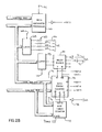
- the system processor 15 is structured about an 8-bit microprocessor 35 which couples to an 8-bit bi-directional data bus 36 and a 16-bit address bus 37.
- a least significant byte of address data is output to a latch 38 when an ALE control line is active, and immediately thereafter the least significant byte of address data is output to an address latch 39.
- Data is either read from the data bus 36 through a set of bi-directional data gates 40 or output through the data gates 40 to an addressed device coupled to the data bus 36.
- the direction of data flow through the gates 40 is determined by the microprocessor control lines, RD and INTA, which connect to a NAND gate 41 through a set of buffers 42.
- These two control lines along with the remaining microprocessor control lines (CLKOUT, WR, 10/M, RST ⁇ ) form a control bus 43 which connects to a number of system elements.
- a random access, read/write memory (RAM) 44 connects to the address bus 37 and data bus 36.
- the RAM 44 stores a variety of data structures which are employed by the register control system and which may be separately read into the microprocessor 35 for processing or which may be altered by a write operation.
- a chip select control line 45 enables the RAM 44 and a memory write control line 46 determines whether a read or write operation is performed.
- the processor 15 also includes a read-only memory (ROM)47 which stores machine language program instructions and constants. The ROM 47 is enabled when a chip select control line 48 is active and addressed data is read therefrom when a memory read control line 49 is active.
- the program instructions which direct the operation of the microprocessor 35 are sequentially read from the ROM 47 and executed to control the operation of the system processor 15.
- a decoder circuit 50 connects to the address bus 37 and control bus 43.
- the decoder circuit 50 includes 2-to-4 and 3-to-8 decoder circuits along with associated gates which generate chip select signals to the various system elements. These include the RAM control line 45 and ROM control line 48 which are enabled when an address whithin their range appears on the address bus 37. ,
- an interrupt controller circuit 51 connects to the data bus 36 and control bus 43.
- the interrupt controller 51 accepts interrupt requests generated on four lines INT ⁇ , INT3, INT4 and INT7, determines which request has the highest priority, determines whether the incoming request has a higher priority than the process currently being serviced, and issues an interrupt through INT control line 52 to the microprocessor 35 based on this determination.
- An 8259 programmable interrupt controller manufactured by Intel Corporation is employed and it is enabled to receive control data from the data bus 36 by a control line 53 which is driven by the decoder circuit 50.
- a universal asynchronous receiver/transmitter (UART) 54 generates one of the interrupt requests (INT4) whenever it receives or transmits a character.
- the UART 54 connects to the data bus 36 and it is enabled through a control line 55.
- a character may be output through the UART 54 for transmission through a serial output circuit 56 or a character may be input serially through input circuit 57 and read from the UART 54.
- the circuits 56 and 57 interface the UART 54 to a serial data link 58 which connects to the output controller 20.
- the UART 54 serves as the means for outputting control data over a substantial distance, and the system processor 15 may thus be centrally located while the output controller 20 may be located adjacent the printing press 1.
- the system processor 15 includes an arithmetic processor 60 for performing high speed arithmetic functions.
- the processor 60 is enabled by the decoder circuit 50 through a control line 61 and data may be written to it for processing.
- a 9511A processor manufactured by Advanced Devices, Inc. is employed, and when an answer is ready, the processor 60 generates an interrupt request to the interrupt controller 51 through the INT3 control line.
- the interrupt is serviced by the microprocessor 35, it is vectored to a service routine which directs the microprocessor 35 to read the arithmetic result from the arithmetic processor 60 and set a flag in RAM 44 which indicates that the arithmetic processor is available for further computations.
- the system processor 15 receives data from the scanner interface 17 and outputs data to the scanner interface 17 through a parallel I/0 bus 62.
- Four bits of output data are stored in a latch 63 when a chip select control line 64 is driven low by the decoder circuit 50.
- This 4-bit nibble is coupled through resistors 65 to corresponding leads 66 to 69 in the I/O bus 62.
- this data indicates if either of the optical scanners 18 or 19 are to be repositioned, and if so, in which direction.
- Three bits of data are input from the scanner interface 17. Two of these are received at two inputs of a multiplexer 70. These two input signals 71 and 72 are digital representations of the signals generated by respective optical scanners 18 and 19 as the register patterns 25 pass beneath them. One of these two signals is selected for analyses by the multiplexer 70 which has its select terminals connected to the outputs of a latch 73. By enabling the latch 73 through chip select line 74, the microprocessor 35 can write a code to the latch 73 which selects either of the two scanner signals 71 or 72. The selected scanner signal appears at a "Y" output on the multiplexer 70 and its inversion appears at a "W” output. The selected scanner signal is applied directly to RST1 and RST2 inputs on the microprocessor 35 and to gate inputs G ⁇ and G1 on a timer/counter circuit 75.
- the timer/counter 75 is a programmable device which receives data through the data bus 36 when a chip select control line 76 is active. It contains three counters which are preset to given values and which are decremented by pulses received at clock inputs CLK ⁇ , CLK1 and CLK2.
- the clock inputs CLKO and CLK1 are driven by the output of a second timer/counter 77, and the third clock input CLK2 is driven by a gate 78 which receives a press speed feedback signal in the form of a pulse stream produced by a shaft encoder.
- An RST3 control line is enabled when the internal counter driven by the speed feedback signal (CLK2) reaches its terminal count, and this event is employed by the microprocessor 35 to sense press speed.
- the other two counters in the timer/counter 75 generate interrupt requests INT7 and INT4 when their terminal counts are reached. Only one of these counters is operated at any single moment, since the gate inputs G1 and G ⁇ are always in opposite logic states. For example, when the scanner signal at the multiplexer output "Y" is high, counter 1 is enabled through gate G1. The logic low voltage at the "W" output disables counter + through gate Gt and it generates a reset request to the microprocessor 35 through control line RST1. In response the microprocessor 35 reads the value of counter + and resets to a preselected value. When the multiplexer outputs Y and V change logic state the reverse is true. Counter ⁇ becomes active and counter 1 is stopped.
- the reset request on RST2 vectors the microprocessor 35 to a program which reads the value of counter 1 and presets it for the next cycle.
- the timer/counter 75 is thus employed to measure the duration of each light and dark portion of the register pattern 25 as it passes beneath the optical scanner 18 or 19. These measured intervals are employed by the microprocessor 35 to determine the register of each printing unit 2 to 5 as will be described in more detail below.
- the last section of the system processor 15 interfaces with the main control panel 16.
- This interface includes a keyboard/display interface circuit 80 which connects to the data bus 36 and to a number of control lines in the bus 43.
- a model 8279 integrated circuit manufactured by Intel, Inc. is employed and it is programmed with control data from the microprocessor 35 to scan a keyboard matrix 81 and to maintain a display matrix 82.
- the keyboard matric includes a variety of control panel switches which are arranged in an eight-by-eight matrix.
- the interface circuit 80 outputs a sequence of three-bit codes to a 3-to-8 decoder 83 and inputs a corresponding sequence of eight bytes of keyboard data through a bus 84.
- the state of up to sixty-four keys are stored in a keyboard image table inside the interface 80, and this table may be read by the microprocessor 35.
- an output image table is written to the interface circuit 80 by the microprocessor 35 and the keyboard/display interface 80 operates to output this data in sequence through an eight-bit bus 84 to the display matrix 82.
- the display 82 is comprised of individual lamps arranged in an eight-by-sixteen matrix with the sixteen rows being sequentially selected by a 4-bit code applied to a 4-to-16 decoder circuit 85.
- the control panel 16 also includes a 40-digit alphanumeric display subsystem 87 which connects to the data bus 36 and control bus 43.
- a display subsystem model DE/240 manufactured by Digital Electronics Corporation is employed and it is enabled through a control line 88 by the decoder circuit 50.
- ASCII characters, including control characters, may be output to the display 87 and an internal cursor determines where the next ASCII character will appear. This cursor may be moved by outputting ASCII control characters to the display 87.
- the scanner interface 17 couples information between the optical scanners 18 and 19 and the system processor 15.
- the scanner interface 17 includes a pair of identical input circuits 90A and 90B and a pair of identical output circuits 91A and 91B.
- the output circuit 91A connects to the output port leads 66 and 67 in the I/O bus 62 and its output terminal 92A and 93B connect respectively to the scanner motor relay 29 and the scanner motor direction relay 30.
- NAND gates 94 and 95 are applied through inverter gates 94 and 95 to respective NAND gates 96 and 97, and the NAND gates 96 and 97 drive the inputs of an exclusive OR gate 98.
- the OR gate 98 energizes the scanner motor on/off relay 29 through an inverter gate 99 when motion in either direction is indicated.
- the output of NAND gate 97 provides a direction indication which is coupled through inverter gate 100 to energize or de-energize the scanner motor direction relay 30.
- the scanners 18 and 19 can also be positioned manually using a remote control panel 101 which connects to the scanner interface 17.
- This manual mode of operation is used primarily during start-up to orient the scanners 18 and 19 for automatic operation.
- the panel 101 includes a pair of pushbutton switches 102 and 103 which connect to inputs on respective NAND gates 96 and 97. By depressing the pushbutton 102 the operator can move the scanner 18 to the left and by depressing pushbutton 103 the scanner 18 moves to the right.
- the panel 101 also includes a pair of indicator lamps 104 and 105, one of which is energized when the optical scanner 18 is moved in either direction. The lamps 104 and 105 are driven by inverter gates 106 and 107 which connect to the outputs of NAND gates 96 and 97.
- the input circuit 90A of the scanner interface 27 receives an analog electrical signal through the leads 24A from the optical scanner 18 and generates a corresponding digital signal to the system processor 15 through lead 71.
- an analog signal 110 is produced.
- the register pattern 25 includes reference portions 111 and 112 which are printed by one of the printing units 2 to 5 along with reference color marks 113.
- the reference color is preferably black because it produces a strong output signal from the optical scanner 18. Additional colors, indicated by color marks 114 to 116, may be printed by the remaining printing units, and the amplitude of the scanner output signal which they produce will depend on the color of the ink.
- the scanner interface 17 converts this analog signal 110 to a corresponding logic level signal 117 for input to the system processor 15.
- the analog input signal 110 is received through leads 24 and amplified by operational amplifier 120.
- the output of amplifier 120 is applied directly to one input of a comparator 121 and to the inputs of a positive precision peak detector formed around amplifier 122 and a negative precision peak detector formed around amplifier 123.
- the outputs of the peak detectors 122 and 123 are buffered by amplifiers 124 and 125 and summed at potentiometer 126.
- the reference signal produced at potentiometer 126 is applied to the inverting input of the comparator 121, and it serves as a voltage level which is proportional to approximately twenty percent of the peak signal produced by the optical scanner 18. As shown in Fig. 6, this reference level is indicated by dashed line 127 and it is well below the minimum signal produced by any colored mark in the register pattern 25.
- the comparator 121 is thus driven sharply into and out of saturation to produce the digitized output signal 117 on the lead 71.
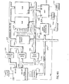
- the output controller 20 receives command data from the system processor 15 through the serial data link 58 and operates the motors which control the register for each printing unit 2 to 5.
- the output controller 20 is microprocessor-based and includes many of the same circuit elements as the system processor 15. Indeed, these same elements are indicated with the same reference numbers as in Fig. 2A, but with the prefex "2" to distinguish them from the corresponding system processor elements.
- the RAM 244 and ROM 247 are the same as the corresponding elements in the system processor, it can be appreciated that the data structures and programs stored therein are different and that their size need not be the same.
- the input/output section of the output controller 20 is substantially different than that of the system processor 15. It includes a set of four 8-bit latches 130 to 133 which connect to the data bus 236 and which are separately enabled through chip select lines 134 to 137 driven by the decoder circuit 250. An 8-bit byte of data may be written to a selected latch 130 to 133 when a write control line WR is driven low.
- the outputs of each latch 130 to 133 are connected through line drivers 138 to relays which operate the register control motors on each printing unit 2 to 5.
- the latch 130 drives the four motors (upper lateral, upper rotational,lower lateral and lower rotational) on the first printing unit 2.
- the upper rotational motor is energized in the forward direction by outputing a logic "1" to the bit 3 position of latch 130.
- a logic "0" is output to de-energize the same motor.
- a 4-bit latch 140 connects to the data bus 236 and is enabled through a chip select line 141 to apply a 4-bit code to the select inputs of a multiplexor 142.
- the sixteen inputs on the multiplexor 142 connect to input circuits 143 which receive signals from each register control motor on the press 1 indicating whether or not the motor is energized.
- a chip select line 144 is enabled, one of the sixteen inputs to the multiplexor 142 is selected and the signal thereon is applied to a serial input port SID on the microprocessor 235.
- the system could be formed as a single microprocessor-based unit, it is physically convenient to separate the output controller from the centrally located system processor 15 in most installations.
- the output controller 20 is usually located on the press 1 with other press control electronics.
- the hardware disclosed herein is shown controlling four printing units for a single web 6. However, it may be more economical in some installations to use the same system processor to control register on additional printing units for additional webs. Indeed, the system processor 15 and output controller 20 disclosed herein have been employed to control register for both sides of two webs, or in other words, eight printing units and four optical scanners.
- register marks 111 to 116 in the register pattern 25 are employed to control color-to-color register.
- a series of voltage pulses are produced as shown at 110.
- Each register mark 113 to 116 is comprised of two triangular sections that produce two voltage pulses of equal time duration. If the focal point of the scanner is not centered as shown by the dashed line 151 in Fig. 7B, the two pulses produced by the reference mark 113 are not of equal duration.
- the system processor 15 When this condition is sensed by the system processor 15, it outputs signals to the scanner interface 16 which reposition the optical scanner 18 or 19 at the center of the pattern. Thus, if the web 6 shifts laterally as it passes through the dryer 7 and chill unit 8, the optical scanners18 and 19 will automatically track the movement.
- the register mark 115 which it produces will not be properly aligned. With the optical scanner properly centered as indicated by dashed line 152, the two voltage pulses produced by the register mark 115 will be unequal in duration. If the misregister is to the left as shown, the first pulse will be shorter, and if the misregister is to the right, the second voltage pulse will be shorter. Either situation is sensed by the system processor 15 which monitors the scanner waveform 117 (Fig. 6) and which outputs corrective commands to the output controller 20 to move the print cylinder back into register.
- the register mark 114 which it produces will not be properly aligned in the register pattern 25. More specifically, the two voltage pulses produced by the register mark 114 are either advanced or delayed relative to the remainder of the registration pattern 25. As shown in Fig. 7A the leading and trailing edges of the register mark 114 are 5.40 and 6,35 cm (2.125 and 2.50 inches) respectively from the leading edge of the pattern 25 when register is proper. The center of the mark 114 is, therefore, 5.87 cm (2.3125 inches) from the pattern reference point when the printing unit 3 is in register. As will be explained in more detail below, the system processor 15 analyzes the signal 117 (Fig.
- the register control system can be operated in a conventional "open loop", or “manual" mode in which the human operator enters corrective data into the system through the main control panel 16.
- corrective data is processed by the system processor 15 to form an alignment command which is output to the controller 20.
- Such an alignment command may, for example, direct that the register control motor for the upper portion of the printing unit 2 be energized to move laterally 12.7/1000 of a cm (five-thousandths of an inch).
- the output controller 20 accepts such commands and operates the proper motor to carry out the alignment motion.
- the human operator checks the register of the signatures at the output of the press to determine if further corrections are necessary.
- system of the present invention may be operated in this conventional manual mode, it can also be switched to an automatic mode in which the register of the signatures is examined by the optical scanner 18 or 19 and appropriate alignment commands are automatically produced and output to the controller 20. While the automation of this process may appear straight forward, in practice there are many difficulties which must be overcome.
- the register pattern 25 may not print accurately or properly at all times.
- One of its marks may not be properly aligned with the image which it is to register, or the pattern may be distored by stretching of the web due to press tension.
- the web has a certain amount of random lateral motion, or "jitter", as it moves through the press which produces a corresponding random misregister.
- Such random misregister can be caused by other factors as well, such as momentary variations in web thickness. It is neither possible nor desirable to make register corrections in response to such short term changes. The human operator is capable of discerning the difference between these random short term changes and long term changes in register, and it-is important that the automatic register control do the same.
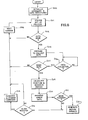
- a set of instructions indicated by process block 200 is executed to initialize the system hardware and the data structures stored in the RAM 44 (Fig. 2A).
- a loop is then entered in which a set of instructions, indicated by process block 201, is executed to enable the operator to enter data.
- this set-up data includes information about the particular printing job, such as which printing unit is the reference unit and which register marks are produced by which units.
- the set-up data may pertain to the press, such as its characteristic jitter and its speed.
- the operator may also enter offset data which compensates for errors in the printing of the register pattern 25.
- a data collection sequence is begun for one surface of the web 6.
- This sequence includes a preparation phase indicated by process block 203 in which a data table 204 in the RAM 44 is cleared. Referring to Fig. 2B, such preparation includes the selection of the proper input channel on the multiplexer 70 and the presetting of the counter (2) in the timer/counter 75.
- the counter (2) is decremented by pulses received from an encoder on the printing press, and when decremented to zero, an interrupt request is generated on line RST3.
- the counter (2) is preset to a value which will result in an interrupt after the plate cylinders in each press unit have rotated two and one-quarter revolutions. This ensures that at least two register patterns 25 are scanned during the data acquisition interval.
- the actual data acquisition is accomplished by two interrupt driven routines which store a sequence of numbers in the data table 204.
- process block 206 the numbers stored in the data table 204 are examined to determine if the register patterns 25 were correctly and accurately scanned. As indicated at decision block 207, if good data was not obtained, the system loops back through process block 208 to collect data on the other surface of the web 6. As indicated above, there are many reasons why poor register data may be obtained, but in most instances the situation corrects itself and good data may be collected a moment later.
- the data is analyzed and used both to correct the lateral position of the scanner 18 or 19 and to correct the register of the printing units 2 to 5.
- the errors in both scanner position and color register are calculated.
- the errors are computed by averaging the errors indicated by the two register patterns scanned during the data acquisition sequence.
- This averaged error data is then processed as indicated by block 210, to determine if corrections should be made. This further processing is designed to eliminate needless corrections where the measured errors are due to short term random events such as jitter.
- a routine indicated by process block 212 is executed. Referring to Figs. 2B and 5, this routine 212 writes data to the latch 63 which energizes the proper scanner motor 28 in the desired direction.
- the counter (2) in the timer/counter circuit 75 is then preset to an appropriate value, and when it "times out", the scanner motor 28 is turned off by again writing to the latch 63. In this manner, the scanner 18 or 19 can be moved to the left or right to "track" the register patterns 25 being printed on the web 6.
- a routine 214 is executed to generate alignment commands to the output controller 20.
- the routine 214 generates a message to the output controller 20 through the UART 54.
- This message is a command that identifies the print unit, web surface and the lateral or rotational motor.
- the alignment command also indicates the direction of the move and the distance in 2.54/1000 of a cm (thousandths of an inch). Referring particularly to Figs.
- the output controller 20 receives this alignment command at its UART 254 and writes an appropriate bit pattern to one of the output latches 130 to 133 to energize the proper alignment motor for the time needed to move this commanded distance.
- the system loops back to the process block 208 to scan the other surface of the web 6.
- the register control system collects data from one web surface, makes corrections to scanner position and color register when necessary, and then repeats the sequence with the other web surface.
- the number of print surfaces which can be monitored in this manner need not be limited to two.
- the system is much faster than human operators in making register corrections, even when four print surfaces are scanned and even when a significant portion of the collected scanner data is discarded as unacceptable.
- one of the functions of the process indicated by block 210 is to average the large amount of collected data, and to thereby effectively slow the response of the register control system to a level which is appropriate to the particular press and printing process being controlled.
- Each data collection cycle is comprised of a series of interrupts which are produced by the scanner signal appearing at the Y and V outputs on the multiplexer 70.
- this cycle is initiated by first presetting the counter (2) in the timer/counter 75 to a value which represents two and one-quarter revolutions of a plate cylinder.
- the RST2 and RST3 interrupts are then enabled as indicated at process block 221, and the system then waits for the RST3 interrupt to occur at process block 222.
- Incremental position feedback pulses are applied to decrement the counter (2) through the gate 78, and after two and one-quarter plate cylinder revolutions, and RST3 interrupt occurs and the data collection cycle is terminated. As indicated at process block 223, the three interrupts RST1, RST2 and RST3 are then disabled and the system proceeds to examine the collected data.
- a series of logic high (light) and logic low (dark) signals are produced and a corresponding series of RST1 and RST2 interrupts occur. That is, when the scanner "sees" a mark in the pattern 25 an RST1 interrupt is produced, and when it sees light, and RST2 interrupt is produced.
- an RST2 interrupt occurs immediately after the data collection cycle begins and the system is vectored to an RST2 interrupt routine. As indicated at process blocks 225 and 226, the first functions performed by this routine is to disable further RST2 interrupts and to enable the RST1 interrupt.
- the counter (1) in the timer/counter 75 is then enabled and the counter (0) is disabled.
- the value of counter (0) is then read from the timer/counter 75 and saved in the data table 204 of the RAM 44 (Fig. 2A), as indicated at process block 228.
- the counter (0) is then reset, as indicated at process block 229, and the system returns to await the RST1 interrupt.
- an RST1 interrupt occurs.
- the system is vectored to a service routine which disables the RST1 interrupt and enables the RST2 interrupt as indicated at process blocks 230 and 231.
- the counter (1) in the timer/counter 75 is then disabled and counter (0) is enabled to start counting, as indicated at process block 232.
- the count in counter (1) is then read from the timer/counter 75 and saved in the data table 204, as indicated at process block 233; and the counter (1) is reset at process block 234 in preparation for the next RST2 interrupt.
- the RST1 and RST2 interrupts occur alternately during the data collection cycle as the scanner 18 or 19 alternately sees light and dark segments of the register patterns 25.
- the counter values which are stored in the data table 204 by the RST1 and RST2 interrupt routines represent the duration of each light or dark segment seen by the scanner 18 or 19 and these numbers can be converted to dimensions which correlate with those dimensions illustrated in Fig. 7A.
- the data collection sequence is terminated when an RST3 interrupt occurs after two and one-quarter revolutions of each printing unit plate cylinder.
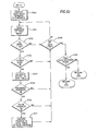
- the RST3 interrupt service routine is then executed,and the first function, as indicated by process block 250, is to convert the sequence of counter numbers stored in the data table 204 to corresponding dimensions. These dimensions indicate the size of each mark and their spacing.
- the size of each mark is then read from the data table 204 and examined to determine if it is the 2.54 cm (one inch) reference mark 111 which indicates the beginning of the register pattern 25. If not, as determined at decision block 252, the system loops to read the next mark from the data table 204.
- the system loops at decision block 253 to continue the search for valid data.
- the dimensions thereof are calibrated as indicated by process block 254. This is accomplished by finding the distance between the leading edge of the 2.54 cm (one inch) reference mark 111 and the leading edge of the 1.27 cm (one-half inch) reference mark 112. This distance should be exactly 11.43 cm (four and one-half inches), and all of the data table entries are scaled to exactly produce this distance.
- This distance measurement is employed to calibrate the dimensions in the data table 204 because the measurement between leading edges of the reference marks 111 and 112 is relatively immune to inking problems. Smearing usually occurs at the trailing edge, not the leading edge, and the growth of marks due to an over- abundance of ink affects both leading edges equally.
- the reference color marks 113 are examined next to determine if they are present and are printed properly. If not, as indicated at decision block 255, the system loops and continues the search for good data. The same tests are then performed on the color marks 114 to 116 as indicated at decision block 256, and if good data is obtained for the entire register pattern 25, the location of this data in the table 204 is identified, as indicated by process block 257.
- the system continues to read from the data table 204 until the last entry is reached. When this occurs, as determined at decision block 258, a test is made at decision block 259 to determine if good data for two register patterns 25 has been located. If so, the system returns to process the data, otherwise, the data is discarded and the system loops to scan the other web surface as shown in Fig. 8.
- each mark 113 to 116 is comprised of an upper section 260 and a lower section 261.
- the sections 260 and 261 are triangular in shape, and when formed properly, they have a combined length L which is constant regardless of their position relative to the scanner path 262 and 263.
- the scanner path 262 passes through the sections 260 and 261 left of center to produce entries in the data table 204 of duration Xu1 and X L 1.
- the scanner path 263 passes through the sections 260 and 261 right of center to produce entries in the data table 204 of duration X u 2 and X L 2. Regardless of the scanner path, the sum of these readings is a constant value and a significant deviation from this constant value indicates that the register mark is not properly printed. That is: This diagnostic check is made by a set of instructions which are listed in Appendix A and which are executed as part of the decision blocks 255 and 256 shown in Fig. 10.
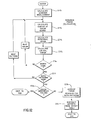
- the scanner misalignment is calculated first as indicated by process block 270. This is accomplished by measuring the difference between the measured length (A) on the upper section 271 of the reference mark 113 and the measured length (B) of the lower section 272.
- the misalignment, or tracking error, of the scanner 18 or 19 is given by the following expression:
- a loop is then entered in which the rotational - and lateral register error for each print unit is calculated.
- the center C1 to C4 of each mark 113 to 116 is calculated by averaging the distance to its leading edge and its trailing edge. This method has been found to provide good immunity to colorimetry changes, since colorimetry changes usually cause both the leading and trailing edges to shift equally toward or away from the center.
- the centerlines of each mark 113 to 116 are ideally spaced 1.91 cm (.75 inches) apart and any deviation from this pattern is a direct measure of rotational misregister of the print unit.
- the rotational register error indicated by the respective color marks 114 to 116 is calculated as follows: These values are calculated at process block 274 and saved in the RAM 44 (Fig. 2A).
- the lateral register error for a printing unit is calculated next as indicated at process block 275. If the color marks 114 and 116 are in perfect register, they should be "off-center" by the same amount as the reference mark 113.
- the lateral register error indicated by the respective color marks 114 to 116 is calculated as follows: The division by 2 in these equations accounts for the 45-degree angle of the hypotenuse of the color triangles.
- each color mark 114 to 116 is analyzed as determined at decision block 276, the same analysis is performed on the data obtained for the second register pattern 25.
- the errors indicated by each pattern are compared. If the measured errors are substantially different, bad data is indicated and the system branches at decision block 278. Otherwise, the errors indicated by the two scanned register patterns 25 are averaged and saved in the RAM 44 as indicated at process block 279. This averaging step eliminates needless register corrections which would otherwise occur due to "packing errors".
- the color marks 114 to 116 may indicate a register error, this does not necessarily indicate that the print images are out of register.
- the register marks 114 to 116 are generally laid down separately from the print image material on the plate, and perfect alignment is difficult.
- the register indicated by the marks may require an offset to give correct register of the print image.
- This offset may be entered by the operator during system set-up (Fig. 8) and the offset values are stored in a table 280 in the RAM 44 (Fig. 2A). These offsets are added to the measured register errors at process block 281 to provide register error data which is stored in a table 282 in the RAM 44.
- this error data is employed to form motion commands to the scanner interface 17 to realign the scanner 18 or 19 with the center line of the register patterns 25. This data is also employed to produce alignment commands for the output controller 20 which correct the register errors in each printing unit 2 to 5.
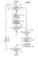
- the error data in table 282 is processed at block 210 prior to the formation of any scanner motion signal or alignment command. This processing is indicated by the flow chart of Fig. 14, and it is intended to further eliminate needless corrections.
- a loop 290 is entered which processes the register error data for each print unit in the press, and when the data for all print units has been processed, as determined at decision block 291, the loop 290 is exited.
- a correction is made.
- This preset limit is entered by the operator during the set-up process, and it is typically set to a value which is greater than the random jitter characteristic of the press. Register errors less than this limit may be self-correcting and changes are not made immediately. Instead, as indicated by process block 293, the most recent register error reading is averaged with the N-1 previous error readings. The standard deviation of these n register error readings is then calculated at process block 294, and the average error is compared with this standard deviation. The standard deviation can be viewed as a measure of the uncertainty of the register error readings, and as long as the average error is less than this uncertainty, no corrections are made. When the average error increases above this uncertainty level however, a register correction is needed, as indicated at decision block 295. The number of readings (N) which are averaged in this manner is selected by the operator during the set-up process.
- a register alignment command for the proper printing unit 2 to 5 and web surface is formed.
- the alignment command may alter either rotational or lateral register or both.
- the command is output to the output controller 20 which operates to execute the alignment command.
- a timer associated with the printing unit 2 to 5 and web surface which is affected by this alignment command is then preset to provide the necessary delay time.
- a delay table 299 is stored in the RAM 44 which includes a "software" timer for each printing unit and web surface. The appropriate timer is set at process block 298 with the proper delay time, and this delay time is subsequently measured by periodic comparison with a real time clock formed by the timer/counter circuit 77 (Fig. 2B).
- the register control system controls the register of each printing unit relative to the printing unit which produces the reference marks 111, 112 and 113. Because register is measured relative to the reference marks 111, 112 and 113, rather than being measured relative to the frame of the press, any changes in the register of the reference printing unit will be corrected by making corresponding changes in the register of each color printing unit. While it is preferable this "reference" printing unit produces a black image, the selection of a reference printing unit and the number and position of the color printing units may be determined by the operator during the set-up process.
Landscapes
- Engineering & Computer Science (AREA)
- Mechanical Engineering (AREA)
- Inking, Control Or Cleaning Of Printing Machines (AREA)
Applications Claiming Priority (2)
| Application Number | Priority Date | Filing Date | Title |
|---|---|---|---|
| US48840183A | 1983-04-25 | 1983-04-25 | |
| US488401 | 1983-04-25 |
Publications (2)
| Publication Number | Publication Date |
|---|---|
| EP0123305A2 true EP0123305A2 (de) | 1984-10-31 |
| EP0123305A3 EP0123305A3 (de) | 1985-10-30 |
Family
ID=23939587
Family Applications (1)
| Application Number | Title | Priority Date | Filing Date |
|---|---|---|---|
| EP84104516A Withdrawn EP0123305A3 (de) | 1983-04-25 | 1984-04-20 | Einrichtung zur Registerregelung für Druckmaschinen |
Country Status (2)
| Country | Link |
|---|---|
| EP (1) | EP0123305A3 (de) |
| JP (1) | JPS6034860A (de) |
Cited By (20)
| Publication number | Priority date | Publication date | Assignee | Title |
|---|---|---|---|---|
| WO1986005141A1 (fr) * | 1985-03-08 | 1986-09-12 | Bertin & Cie | Procede et dispositif de positionnement d'objets les uns par rapport aux autres, en particulier des rouleaux d'impression de couleurs dans une presse rotative offset |
| US4652914A (en) * | 1984-04-27 | 1987-03-24 | Dainippon Screen Mfg. Co., Ltd. | Method of recording register marks |
| GB2181697A (en) * | 1985-10-16 | 1987-04-29 | Sanders Associates Inc | Transverse registration in printing apparatus |
| EP0240950A3 (en) * | 1986-04-07 | 1989-08-30 | Quad/Tech, Inc. | Web registration control system |
| GB2218046A (en) * | 1988-04-02 | 1989-11-08 | Heidelberger Druckmasch Ag | Determining registration errors in printing apparatus |
| US4882764A (en) * | 1985-03-29 | 1989-11-21 | Quad/Tech, Inc. | Cutoff control system |
| US4885785A (en) * | 1986-10-31 | 1989-12-05 | Quad/Tech, Inc. | Cutoff control system |
| US5076163A (en) * | 1986-04-07 | 1991-12-31 | Quad/Tech, Inc. | Web registration control system |
| FR2676129A1 (fr) * | 1991-04-30 | 1992-11-06 | Cer Ets | Procede destine a positionner un objet par rapport a un element a emplacement determine ou vice et versa et machine pour sa mise en óoeuvre. |
| GB2271744A (en) * | 1992-10-24 | 1994-04-27 | Univ Montfort | Registration in printing and other operations. |
| US5329466A (en) * | 1991-11-14 | 1994-07-12 | Bobst Sa | Registration control device for use in a rotary printing machine |
| GB2326615A (en) * | 1997-06-27 | 1998-12-30 | Tecscan Electronics Limited | Print monitoring |
| DE102004023041A1 (de) * | 2004-05-06 | 2005-11-24 | Eastman Kodak Co. | Verfahren zur Ausrichtung von Farbauszügen eines Druckbildes auf einem Bedruckstoff |
| EP1201429A3 (de) * | 2000-10-24 | 2007-10-03 | Goss Contiweb B.V. | Verfahren und Vorrichtung zum Kühlen einer Materialbahn |
| US8931874B1 (en) | 2013-07-15 | 2015-01-13 | Eastman Kodak Company | Media-tracking system using marking heat source |
| US8960842B2 (en) | 2013-07-15 | 2015-02-24 | Eastman Kodak Company | Media-tracking system using thermal fluoresence quenching |
| US9056736B2 (en) | 2013-07-15 | 2015-06-16 | Eastman Kodak Company | Media-tracking system using thermally-formed holes |
| US9429419B2 (en) | 2013-07-15 | 2016-08-30 | Eastman Kodak Company | Media-tracking system using deformed reference marks |
| US10976263B2 (en) | 2016-07-20 | 2021-04-13 | Ball Corporation | System and method for aligning an inker of a decorator |
| US11034145B2 (en) | 2016-07-20 | 2021-06-15 | Ball Corporation | System and method for monitoring and adjusting a decorator for containers |
Families Citing this family (2)
| Publication number | Priority date | Publication date | Assignee | Title |
|---|---|---|---|---|
| JPH06164561A (ja) * | 1992-11-18 | 1994-06-10 | Nec Corp | ディジタル無線通信切替装置 |
| JP6341870B2 (ja) * | 2015-02-25 | 2018-06-13 | 住友重機械工業株式会社 | 見当制御ユニット、見当制御ユニットを備える多色刷印刷システムおよび見当制御方法 |
Family Cites Families (2)
| Publication number | Priority date | Publication date | Assignee | Title |
|---|---|---|---|---|
| GB980471A (en) * | 1962-01-30 | 1965-01-13 | Linotype Machinery Ltd | Improvements in printing presses |
| US3701464A (en) * | 1970-10-15 | 1972-10-31 | Harris Intertype Corp | Circumferential and lateral web registration control system |
-
1984
- 1984-04-20 EP EP84104516A patent/EP0123305A3/de not_active Withdrawn
- 1984-04-24 JP JP59082796A patent/JPS6034860A/ja active Pending
Cited By (31)
| Publication number | Priority date | Publication date | Assignee | Title |
|---|---|---|---|---|
| US4652914A (en) * | 1984-04-27 | 1987-03-24 | Dainippon Screen Mfg. Co., Ltd. | Method of recording register marks |
| US4679071A (en) * | 1984-04-27 | 1987-07-07 | Dainippon Screen Manufacturing Co., Ltd. | Method of recording register marks |
| US4932320A (en) * | 1985-03-08 | 1990-06-12 | Michel Brunetti | Method and device for registering colors in an offset rotary press |
| FR2578486A1 (fr) * | 1985-03-08 | 1986-09-12 | Bertin & Cie | Procede et dispositif de positionnement d'objets les uns par rapport aux autres, en particulier des rouleaux d'impression de couleurs dans une presse rotative offset |
| WO1986005141A1 (fr) * | 1985-03-08 | 1986-09-12 | Bertin & Cie | Procede et dispositif de positionnement d'objets les uns par rapport aux autres, en particulier des rouleaux d'impression de couleurs dans une presse rotative offset |
| US4882764A (en) * | 1985-03-29 | 1989-11-21 | Quad/Tech, Inc. | Cutoff control system |
| GB2181697A (en) * | 1985-10-16 | 1987-04-29 | Sanders Associates Inc | Transverse registration in printing apparatus |
| GB2181697B (en) * | 1985-10-16 | 1990-07-04 | Sanders Associates Inc | Multiple information array registration apparatus and method |
| US5076163A (en) * | 1986-04-07 | 1991-12-31 | Quad/Tech, Inc. | Web registration control system |
| US4887530A (en) * | 1986-04-07 | 1989-12-19 | Quad/Tech, Inc. | Web registration control system |
| AU611634B2 (en) * | 1986-04-07 | 1991-06-20 | Quad/Tech, Inc. | Web registration control system |
| EP0240950A3 (en) * | 1986-04-07 | 1989-08-30 | Quad/Tech, Inc. | Web registration control system |
| US4885785A (en) * | 1986-10-31 | 1989-12-05 | Quad/Tech, Inc. | Cutoff control system |
| GB2218046A (en) * | 1988-04-02 | 1989-11-08 | Heidelberger Druckmasch Ag | Determining registration errors in printing apparatus |
| GB2218046B (en) * | 1988-04-02 | 1991-11-27 | Heidelberger Druckmasch Ag | Printed product register error determination apparatus |
| FR2676129A1 (fr) * | 1991-04-30 | 1992-11-06 | Cer Ets | Procede destine a positionner un objet par rapport a un element a emplacement determine ou vice et versa et machine pour sa mise en óoeuvre. |
| US5329466A (en) * | 1991-11-14 | 1994-07-12 | Bobst Sa | Registration control device for use in a rotary printing machine |
| GB2271744A (en) * | 1992-10-24 | 1994-04-27 | Univ Montfort | Registration in printing and other operations. |
| GB2271744B (en) * | 1992-10-24 | 1996-05-01 | Univ Montfort | Registration in printing and other operations |
| GB2326615A (en) * | 1997-06-27 | 1998-12-30 | Tecscan Electronics Limited | Print monitoring |
| EP1201429A3 (de) * | 2000-10-24 | 2007-10-03 | Goss Contiweb B.V. | Verfahren und Vorrichtung zum Kühlen einer Materialbahn |
| DE102004023041A1 (de) * | 2004-05-06 | 2005-11-24 | Eastman Kodak Co. | Verfahren zur Ausrichtung von Farbauszügen eines Druckbildes auf einem Bedruckstoff |
| DE102004023041B4 (de) * | 2004-05-06 | 2012-02-16 | Eastman Kodak Co. | Verfahren zur Ausrichtung von Farbauszügen eines Druckbildes auf einem Bedruckstoff |
| US8245638B2 (en) | 2004-05-06 | 2012-08-21 | Eastman Kodak Company | Method for aligning color separations of a printing image on a printing material |
| US8931874B1 (en) | 2013-07-15 | 2015-01-13 | Eastman Kodak Company | Media-tracking system using marking heat source |
| US8960842B2 (en) | 2013-07-15 | 2015-02-24 | Eastman Kodak Company | Media-tracking system using thermal fluoresence quenching |
| US9056736B2 (en) | 2013-07-15 | 2015-06-16 | Eastman Kodak Company | Media-tracking system using thermally-formed holes |
| US9211751B2 (en) | 2013-07-15 | 2015-12-15 | Eastman Kodak Company | Media-tracking system using marking laser |
| US9429419B2 (en) | 2013-07-15 | 2016-08-30 | Eastman Kodak Company | Media-tracking system using deformed reference marks |
| US10976263B2 (en) | 2016-07-20 | 2021-04-13 | Ball Corporation | System and method for aligning an inker of a decorator |
| US11034145B2 (en) | 2016-07-20 | 2021-06-15 | Ball Corporation | System and method for monitoring and adjusting a decorator for containers |
Also Published As
| Publication number | Publication date |
|---|---|
| EP0123305A3 (de) | 1985-10-30 |
| JPS6034860A (ja) | 1985-02-22 |
Similar Documents
| Publication | Publication Date | Title |
|---|---|---|
| US4596468A (en) | System for scanning color printing register marks printed on the printed sheets | |
| AU611634B2 (en) | Web registration control system | |
| KR950006818B1 (ko) | 오프셑 윤전기에서 칼라 인쇄롤의 위치선정 방법 및 장치 | |
| US4553478A (en) | Printing machine pre-setting arrangement | |
| US5076163A (en) | Web registration control system | |
| JPS6034860A (ja) | 印刷機用見当制御装置 | |
| US4428287A (en) | Method for production of impressions of accurate register on printing presses | |
| EP1428659B1 (de) | Verfahren und Vorrichtung zur Bestimmung des Registerfehlers, und Vorrichtung zur automatischen Regelung des Registers für Mehrfarbenrotationsdruckmaschinen | |
| US5313886A (en) | Electronic method of positioning a register mark sensor of a sheet printing machine | |
| US4827626A (en) | Method and apparatus for register correction | |
| US4963029A (en) | Register-measuring system | |
| US5255598A (en) | Screen printing device with continuous registering of rotating stencils | |
| US4857745A (en) | Method and apparatus for monitoring the passage of marks on a web | |
| US5774225A (en) | System and method for color measurement and control on-press during printing | |
| US4856903A (en) | Electronic device for determining a register error in multi-color printing machines | |
| US20040042022A1 (en) | Active color control for a printing press | |
| JPH0375345B2 (de) | ||
| US6018687A (en) | Method and apparatus for printing cutoff control using prepress data | |
| EP0860277B1 (de) | System und Verfahren zur Registerregelung in einer Druckmaschine während der Einstellung und des Bedruckens | |
| US5448949A (en) | Method and device for adjusting a contact pressure between ink-carrying cylinders of a printing machine | |
| US5649484A (en) | Electronic apparatus and computer-controlled method for alignment correction | |
| US5014618A (en) | Sensor based inking control for a printing press | |
| EP0835753A1 (de) | Voreinstellungssystem für eine Rollenrotationsdruckmaschine | |
| EP0274061A2 (de) | Synchronisierung von Messpunkten für einen abtastenden Densitometer | |
| JPH06294607A (ja) | 回転する胴の表面上の枚葉紙縁部の位置を測定するための装置 |
Legal Events
| Date | Code | Title | Description |
|---|---|---|---|
| PUAI | Public reference made under article 153(3) epc to a published international application that has entered the european phase |
Free format text: ORIGINAL CODE: 0009012 |
|
| AK | Designated contracting states |
Designated state(s): DE FR GB |
|
| PUAL | Search report despatched |
Free format text: ORIGINAL CODE: 0009013 |
|
| AK | Designated contracting states |
Designated state(s): DE FR GB |
|
| STAA | Information on the status of an ep patent application or granted ep patent |
Free format text: STATUS: THE APPLICATION IS DEEMED TO BE WITHDRAWN |
|
| 18D | Application deemed to be withdrawn |
Effective date: 19861011 |
|
| RIN1 | Information on inventor provided before grant (corrected) |
Inventor name: QUADRACCI, THOMAS A. Inventor name: REYNOLDS, BRUCE A. Inventor name: KIRBY, JERRY L. Inventor name: SAINIO, JEFFREY W. |