EP0123320B1 - Adjustable tangent assembly for a diaphragm gas meter - Google Patents
Adjustable tangent assembly for a diaphragm gas meter Download PDFInfo
- Publication number
- EP0123320B1 EP0123320B1 EP84104664A EP84104664A EP0123320B1 EP 0123320 B1 EP0123320 B1 EP 0123320B1 EP 84104664 A EP84104664 A EP 84104664A EP 84104664 A EP84104664 A EP 84104664A EP 0123320 B1 EP0123320 B1 EP 0123320B1
- Authority
- EP
- European Patent Office
- Prior art keywords
- plate
- stroke
- timing
- crank shaft
- connecting mechanism
- Prior art date
- Legal status (The legal status is an assumption and is not a legal conclusion. Google has not performed a legal analysis and makes no representation as to the accuracy of the status listed.)
- Expired
Links
- 230000007246 mechanism Effects 0.000 claims description 37
- 210000000707 wrist Anatomy 0.000 claims description 18
- 238000006073 displacement reaction Methods 0.000 claims description 7
- 210000001364 upper extremity Anatomy 0.000 description 3
- 230000000295 complement effect Effects 0.000 description 1
- 238000010276 construction Methods 0.000 description 1
- 230000007812 deficiency Effects 0.000 description 1
- 238000003780 insertion Methods 0.000 description 1
- 230000037431 insertion Effects 0.000 description 1
Images



Classifications
-
- G—PHYSICS
- G01—MEASURING; TESTING
- G01F—MEASURING VOLUME, VOLUME FLOW, MASS FLOW OR LIQUID LEVEL; METERING BY VOLUME
- G01F3/00—Measuring the volume flow of fluids or fluent solid material wherein the fluid passes through the meter in successive and more or less isolated quantities, the meter being driven by the flow
- G01F3/02—Measuring the volume flow of fluids or fluent solid material wherein the fluid passes through the meter in successive and more or less isolated quantities, the meter being driven by the flow with measuring chambers which expand or contract during measurement
- G01F3/20—Measuring the volume flow of fluids or fluent solid material wherein the fluid passes through the meter in successive and more or less isolated quantities, the meter being driven by the flow with measuring chambers which expand or contract during measurement having flexible movable walls, e.g. diaphragms, bellows
- G01F3/22—Measuring the volume flow of fluids or fluent solid material wherein the fluid passes through the meter in successive and more or less isolated quantities, the meter being driven by the flow with measuring chambers which expand or contract during measurement having flexible movable walls, e.g. diaphragms, bellows for gases
- G01F3/222—Measuring the volume flow of fluids or fluent solid material wherein the fluid passes through the meter in successive and more or less isolated quantities, the meter being driven by the flow with measuring chambers which expand or contract during measurement having flexible movable walls, e.g. diaphragms, bellows for gases characterised by drive mechanism for valves or membrane index mechanism
- G01F3/223—Measuring the volume flow of fluids or fluent solid material wherein the fluid passes through the meter in successive and more or less isolated quantities, the meter being driven by the flow with measuring chambers which expand or contract during measurement having flexible movable walls, e.g. diaphragms, bellows for gases characterised by drive mechanism for valves or membrane index mechanism with adjustment of stroke or timing; Calibration thereof; Testing
-
- G—PHYSICS
- G01—MEASURING; TESTING
- G01F—MEASURING VOLUME, VOLUME FLOW, MASS FLOW OR LIQUID LEVEL; METERING BY VOLUME
- G01F3/00—Measuring the volume flow of fluids or fluent solid material wherein the fluid passes through the meter in successive and more or less isolated quantities, the meter being driven by the flow
- G01F3/24—Measuring the volume flow of fluids or fluent solid material wherein the fluid passes through the meter in successive and more or less isolated quantities, the meter being driven by the flow with measuring chambers moved during operation
-
- G—PHYSICS
- G01—MEASURING; TESTING
- G01F—MEASURING VOLUME, VOLUME FLOW, MASS FLOW OR LIQUID LEVEL; METERING BY VOLUME
- G01F3/00—Measuring the volume flow of fluids or fluent solid material wherein the fluid passes through the meter in successive and more or less isolated quantities, the meter being driven by the flow
- G01F3/30—Wet gas-meters
Definitions
- the present invention is directed to a tangent assembly for a positive displacement diaphragm gas meter to drivingly couple a flag assembly to a crank shaft, having tangent members movable relative to each other in order to adjust stroke and timing comprising a lock plate non-rotatably connected to said crank shaft along the axis of rotation thereof, a wrist pin connected to one of said tangent members and extending therefrom parallel to said crank shaft axis of rotation and means for connecting said flag assembly to said wrist pin.
- Positive displacement diaphragm gas meters typically are provided with a tangent which drivingly couples the diaphragm driven flag assembly to the crank shaft which is in turn coupled to open and close the slide valves of the meter. It is common practice to provide an adjustable tangent so that the timing of the valves and the stroke of the diaphragm may be adjusted to calibrate the meter.
- a gas meter having a tangent assembly of the described type is known from US patent 3,668,929.
- the known tangent assembly comprises an upper arm which is non-rotatably attached to the crank shaft. Over this upper arm extends the upper leg of a C-shaped wrist to which the wrist pin is attached.
- the lower leg of the wrist extends below the upper arm and is slidably held within a recess of a lower arm.
- the lower arm is slidably attached to the underside of the upper arm.
- the lower leg of the wrist has to be moved within the recess of the lower arm in a linear direction by means of a screw.
- the lower arm together with the wrist has to be moved along the upper arm in a linear direction by means of a second screw.
- a tangent assembly for a positive displacement diaphragm gas meter of the known type which includes a timing plate and a stroke plate pivotally connected to said timing plate, means for pivotally connecting one of said timing and stroke plates to said lock plate, a first connecting mechanism connected between said lock plate and said one of said timing and stroke plates, said first connecting mechanism being adjustable and adapted to vary the distance between its connection point to said lock plate and said one of said timing and stroke plates so as to pivot said one of said timing and stroke plates with respect to said lock plate,
- Claim 9 covers a preferred embodiment of a tool which allows the adjustment of the tangent assembly from the outside of the gas meter.
- Claim 12 contains a preferred embodiment of a housing for a gas meter incorporating a tangent assembly according to the present invention.
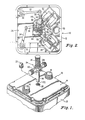
- Fig. 1 shows a rotary positive displacement diaphragm meter, designated generally by the reference numeral 10, having a housing including a body portion 12 and a cover 14.
- the cover 14 includes a gas inlet connector 16 and a gas outlet connector 18, as is conventional in the art.
- the cover 14 is formed with an internally threaded bore 20 which, as will be described in full detail hereinafter, is coaxial with the axis of rotation of the meter crank shaft.
- An externally threaded plug 22 is provided to close the bore 20 during normal operation of the meter 10. However, when the meter 10 is being calibrated or adjusted, the plug 22 is removed.
- the bore 20 is of sufficient size to enable the insertion of the adjusting tool, designated generally by the reference numeral 24 therethrough.
- FIG. 2 shown therein is the gas distributing chamber 26 of the meter 10.
- gas enters the inlet connector 16 and passes into the gas distributing chamber 26 for delivery to the gas measuring chambers (not shown) through the valve seats 28 which control the flow of gas into and out of the gas measuring chambers for subsequent exiting from the meter at the outlet 30 through the outlet connector 18.
- Flag rods 32, 33 are connected to be actuated by the measuring chambers and are fixed to the long flag arms 34, 35, respectively, connected by the short flag arms 36 and 38 to the wrist pin or post 40 fixedly attached to the stroke plate 42 of the improved adjustable tangent assembly, designated generally by the reference numeral 14.
- the reference numeral 14 As is shown more clearly in Fig.
- the tangent assembly 44 has a lock plate 46 nonrotatably connected to a crank shaft 48 having the usual crank connected by arms 50 to slide valves 52 on the valve seats 28.
- the volume of gas measured by the meter 10 is controlled by the valves 52 which in turn are adjustable as to timing and controlled by the diaphragm stroke at the tangent assembly 44.
- the adjustment of the tangent assembly 44 adjusts the position of the wrist pin 40 with respect to the axis of rotation of the crank shaft 48.
- Adjustment along the broken line 54 controls the stroke of the diaphragm flag arms 36 and 38 corresponding to the volume displacement thereof.
- Adjustment along the broken line 56 controls the timing of the valve operation, so as to change the time of opening and closing of the valves 52.
- the broken lines 54 and 56 are substantially perpendicular to each other. With the exception of the improved tangent assembly 44, the described components are or may be of conventional design.
- the tangent assembly 44 includes a lock plate 46 nonrotatably connected to the crank shaft 48 along its axis of rotation 49.
- the lock plate 46 includes an aperture 58 shaped generally from a circle of the same diameter as the upper extremity of the crank shaft 48 but with straightened sides and the upper extremity of the crank shaft 48 is slabbed to be complementary to the aperture 58 so that when the upper extremity of the crank shaft 48 is inserted into the aperture 58, a nonrotatable connection is formed between the lock plate 46 and the crank shaft 48.
- the tangent assembly 44 further includes a timing plate 60 pivotally connected to the lock plate 46 by a pivot pin 62. At the other end of the timing plate 60, a second pivot pin 64 provides a pivotal connection between the timing plate 60 and the stroke plate 42. As was previously mentioned, the stroke plate 42 has fixedly connected thereto the wrist pin 40, to which are connected the flag arms 36 and 38.
- the first connecting mechanism 66 includes a threaded shaft 70 having a gear 72 affixed thereto.
- the shaft 70 is threaded into an adjusting block 74 mounted on, or part of, the timing plate 70, the adjusting block 74 having an internally threaded through bore for accommodating the threaded shaft 70.
- Fig. 3A illustrates an end view of a preferred adjusting block 74 which is seen to have a headed depending portion 76.
- the timing plate 60 is provided with a keyhole-shaped aperture 78 which allows the headed depending portion 76 to be inserted into the large round portion of the aperture 78 and then moved along the elongated portion thereof. Accordingly, the adjusting block 74 is free to slide longitudinally along the aperture 78.
- the lock plate 46 is formed with an upstanding tab 80 having an opening therethrough through which the shaft 70 may extend and in which the shaft 70 may freely rotate.
- the shaft 70 is provided with a head or snap ring (not shown) larger than the opening in the tab 80 and is further provided with a knurled portion between the head and the threads onto which the gear 72 is force fit after the shaft 70 is inserted through the opening in the tab 80. Accordingly, when the gear 72 is rotated, the timing plate 60 is pivoted with respect to the lock plate 46 about the pin 62.
- the second connecting mechanism 68 is similar to the first connecting mechanism 66 and provides a connection between the timing plate 60 and the stroke plate 42. Accordingly, the stroke plate 42 is formed with an extension 82 and the timing plate 60 is formed with a tab 84.
- the extension 82 is formed with an open ended slot (not shown) holding the adjusting block 86, which may be identical in construction to the adjusting block 74.
- the second connecting mechanism 66 also includes a threaded shaft 88 having a head 90 at one end.
- the adjusting block 86 has an internally threaded opening into which the shaft 88 may be screwed.
- the tab 84 has an opening, smaller than the head 90, in which the shaft 88 may freely rotate.
- Press fit onto a knurled portion of the shaft 88 is a gear 92. Accordingly, by turning the gear 92, the distance between the tab 84 and the adjusting block 86 may be varied to cause the stroke plate 42 to pivot with respect to the timing plate 60 about the pivot pin 64.
- the wrist pin 40 is caused to move along the broken line 56, which is a segment of a circle having its center at the pivot pin 62.
- the gear 92 the wrist pin 40 is caused to move along the broken line 54, which is a segment of a circle having its center at the pivot pin 64.
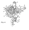
- Fig. 4 illustrates the tangent assembly 44 including the adjusting mechanisms whereby the gears 72 and 92 may be turned to independently vary the stroke and timing. Accordingly, there is provided a first worm 94 engaged with the gear 72 and a second worm 96 engaged with the gear 92.
- the worms 94 and 96 are coaxial, with each having an integral extension 98 and 100, respectively, the ends of which are formed as a pair of concentric face gears 102 and 104, respectively.
- the worm 96 is longitudinally adjacent the worm 94 and external to the extension 98.
- the outside diameter of the extension 98 is slightly less than the inside diameter of the worm 96 so that the worms 94 and 96 are free to rotate with respect to each other.
- the worm 94 is formed with a central axial bore and the first and second adjusting mechanisms are held in place illustratively by a threaded locking screw 106. (Other attachments are of course possible).
- the locking screw 106 has a head 108 at the end opposite the threads and a smooth intermediate portion 110 between the head and the threads.
- the threaded end of the locking screw 106 is secured in an internally threaded bore 112 (Fig. 3) formed in the crank shaft 48 and coaxial with the axis of rotation 49 of the crank shaft 48.
- the outer diameter of the portion 110 of the screw 106 is slightly smaller than the inside diameter of the central axial bore of the worm 94 so that the worm 94 is free to rotate thereabout.
- the extension 98 of the worm 94 is inset inside the face gear 102 so that the upper surface 114 of the head 108 is substantially coplanar with the gears 102 and 104. It is noted that other arrangements for practicing this invention may not be coplanar. For example, the use of bevel gears in place of face gears may result in an arrangement which is not coplanar.
- Fig. 5 illustrates a tool 24, partially in longitudinal section, which may be utilized for effecting adjustment of the tangent assembly 44.
- the tool 24 includes a first tube, or barrel, 116, and a second tube, or barrel, 118, concentric with each other.
- the first tube 116 has a face gear 120 at its free end and the second tube 118 has a face gear 122 at its free end, the face gears 120 and 122 being substantially coplanar. Again, other arrangements may not be coplanar.
- the face gear 120 is adapted to mesh with the face gear 102 of the adjusting mechanism and the face gear 122 is adapted to mesh with the face gear 104 of the adjusting mechanism.
- the tubes 116 and 118 are formed with respective bevel gears 124 and 126.
- the tool 24 is provided with a first adjusting knob 128 having a bevel gear 130 adapted to mesh with the bevel gear 124.
- the tool 24 is further provided with a second adjusting knob 132 having a bevel gear 134 adapted to mesh with the bevel gear 126.
- turning the adjusting knob 128 turns the tube 116 which is adapted to turn the worm 94 to turn the gear 72 to adjust the timing.
- turning the adjusting knob 132 is adapted to adjust the stroke.
- the locking screw 106 is provided with a recessed socket 136, illustratively hexagonal in shape, in its head 108.
- the tool 24 is provided with a locking shaft 138 having a projection 140 shaped complemental to the recessed socket 136. At the end opposite the projection 140, the locking shaft 138 is threadedly or solidly secured to the handle 141 of the tool 24.
- the locking shaft 138 may further be provided with an extending tip 142 and the locking screw 106 may be provided with a further recess 144 which cooperates with the tip 142 for guiding purposes.
- Figs. 7A, 7B, 7C and 7D show a sequence of positions of the deflector plate 146 as the wrist pin 40 travels around the axis of rotation of the crank shaft 48, as indicated by the arrow 148.
- Figs. 7A and 7D illustrate the extremes of the range of positions where the gears 102 and 104 are accessible to the tool 24 for adjustment of the timing and stroke.
- Figs. 7B and 7C illustrate positions where the deflector plate 146 prevents access to the gears 102 and 104.
- Figs. 6A, 6B and 6C illustrate the sequence involved in engaging the tool 24 with the adjusting gears 102 and 104.
- the tool 24 is inserted through the bore 20 in the cover 14 but is prevented from engaging the gears 102 and 104 because the deflector plate 146 is shielding the gears 102 and 104.
- Fig. 6B illustrates the condition where the deflector plate 146 has moved to a position where the gears 102 and 104 are exposed and the tool 24 is inserted sufficiently so that the tip 142 has entered the recessed socket 136 but the gears 120 and 122 are not yet meshed with the gears 102 and 104, respectively.
- Fig. 6B illustrates the condition where the deflector plate 146 has moved to a position where the gears
- 6C illustrates the condition where the tool 24 is fully inserted with the gears 120 and 122 being meshed and the gears 104 and 122 being meshed. Additionally, the projection 140 is inserted in the socket 136 so that crank shaft 48 cannot rotate if the tool 24 is held firmly. Adjustment of the timing and stroke may then be effected through rotation of the adjusting knobs 128 and 132, respectively.
- the aforedescribed arrangement lends itself to both manual and automated adjustment.
- the plug 22 is removed from the cover 14 of the meter 10 and the tool 24 is inserted through the bore 20 into locking engagement with the adjusting mechanism. The technician can then adjust the meter accordingly.
- turning of the adjusting knobs 128 and 132 may be effected through small stepping motors. Very high resolution can be attained because a fixed angular turning of the adjustment knobs corresponds to fixed changes in the timing and stroke.
- the use of worms and worm gears also provides a self locking feature for the adjustment mechanism.
Landscapes
- Physics & Mathematics (AREA)
- Fluid Mechanics (AREA)
- General Physics & Mathematics (AREA)
- Measuring Volume Flow (AREA)
- Details Of Flowmeters (AREA)
Applications Claiming Priority (2)
| Application Number | Priority Date | Filing Date | Title |
|---|---|---|---|
| US06/488,290 US4520676A (en) | 1983-04-25 | 1983-04-25 | Adjustable tangent assembly for a diaphragm gas meter |
| US488290 | 1983-04-25 |
Publications (2)
| Publication Number | Publication Date |
|---|---|
| EP0123320A1 EP0123320A1 (en) | 1984-10-31 |
| EP0123320B1 true EP0123320B1 (en) | 1987-10-28 |
Family
ID=23939126
Family Applications (1)
| Application Number | Title | Priority Date | Filing Date |
|---|---|---|---|
| EP84104664A Expired EP0123320B1 (en) | 1983-04-25 | 1984-04-25 | Adjustable tangent assembly for a diaphragm gas meter |
Country Status (8)
| Country | Link |
|---|---|
| US (1) | US4520676A (da) |
| EP (1) | EP0123320B1 (da) |
| JP (1) | JPS59208423A (da) |
| KR (1) | KR840008975A (da) |
| AU (1) | AU561630B2 (da) |
| CA (1) | CA1199820A (da) |
| DE (2) | DE123320T1 (da) |
| DK (1) | DK100984A (da) |
Families Citing this family (6)
| Publication number | Priority date | Publication date | Assignee | Title |
|---|---|---|---|---|
| DE3623596A1 (de) * | 1986-07-12 | 1988-02-04 | Kromschroeder Ag G | Welle, insbesondere fuer balgengaszaehler |
| US4736657A (en) * | 1986-10-30 | 1988-04-12 | American Meter Company | Adjusting tool |
| DE3707163C1 (en) * | 1987-03-06 | 1988-05-05 | Rombach Gmbh Johann B | Concertina-type gas meter |
| DE4205135A1 (de) * | 1992-02-20 | 1993-08-26 | Kromschroeder Ag G | Kurbelvorrichtung |
| US6772629B1 (en) * | 2003-05-13 | 2004-08-10 | American Meter Company | Diaphragm gas meter tangent assembly utilizing a cam for stroke adjustment |
| WO2012068296A2 (en) | 2010-11-17 | 2012-05-24 | Colin Johnstone | Seismic actuator |
Family Cites Families (10)
| Publication number | Priority date | Publication date | Assignee | Title |
|---|---|---|---|---|
| US876875A (en) * | 1907-03-13 | 1908-01-14 | Thomas Henning | Gas-meter. |
| US1293965A (en) * | 1917-11-13 | 1919-02-11 | Sprague Meter Company | Gas-meter. |
| US1893022A (en) * | 1930-12-24 | 1933-01-03 | Southern California Gas Co | Meter |
| US2775891A (en) * | 1954-08-04 | 1957-01-01 | American Meter Co | Tangents |
| US3011344A (en) * | 1957-11-21 | 1961-12-05 | Rockwell Mfg Co | Fluid meters |
| US3261206A (en) * | 1964-06-23 | 1966-07-19 | Karl L Schaus | Double adjustment crank assembly for diaphragm type gas meters |
| GB1068353A (en) * | 1965-03-08 | 1967-05-10 | Thomas Glover And Company Ltd | Improvements in and relating to gas meters |
| US3411358A (en) * | 1967-03-21 | 1968-11-19 | Textron Inc | Adjustment flange assembly for gas meters |
| JPS507461B1 (da) * | 1967-08-12 | 1975-03-26 | ||
| US3668929A (en) * | 1970-09-08 | 1972-06-13 | Singer Co | Meter tangents |
-
1983
- 1983-04-25 US US06/488,290 patent/US4520676A/en not_active Expired - Lifetime
-
1984
- 1984-02-24 DK DK100984A patent/DK100984A/da not_active Application Discontinuation
- 1984-02-28 CA CA000448406A patent/CA1199820A/en not_active Expired
- 1984-03-02 AU AU25246/84A patent/AU561630B2/en not_active Ceased
- 1984-04-24 JP JP59081263A patent/JPS59208423A/ja active Pending
- 1984-04-24 KR KR1019840002179A patent/KR840008975A/ko not_active Withdrawn
- 1984-04-25 DE DE198484104664T patent/DE123320T1/de active Pending
- 1984-04-25 DE DE8484104664T patent/DE3467038D1/de not_active Expired
- 1984-04-25 EP EP84104664A patent/EP0123320B1/en not_active Expired
Also Published As
| Publication number | Publication date |
|---|---|
| DE123320T1 (de) | 1985-02-14 |
| DK100984A (da) | 1984-10-26 |
| KR840008975A (ko) | 1984-12-20 |
| CA1199820A (en) | 1986-01-28 |
| AU561630B2 (en) | 1987-05-14 |
| US4520676A (en) | 1985-06-04 |
| AU2524684A (en) | 1984-11-01 |
| DK100984D0 (da) | 1984-02-24 |
| JPS59208423A (ja) | 1984-11-26 |
| DE3467038D1 (en) | 1987-12-03 |
| EP0123320A1 (en) | 1984-10-31 |
Similar Documents
| Publication | Publication Date | Title |
|---|---|---|
| EP0123320B1 (en) | Adjustable tangent assembly for a diaphragm gas meter | |
| WO1991003345A1 (de) | Werkzeugkopf für den einsatz in werkzeugmaschinen | |
| DE2660963C2 (da) | ||
| EP0139943A2 (de) | Drosselvorrichtung | |
| DE3828887C2 (de) | Prallscheiben-Strömungsmesser | |
| DE4115253C2 (da) | ||
| EP0257259B1 (de) | Welle, insbesondere für Balgengaszähler | |
| EP1014065A1 (de) | Messsystem für ein Druckmessgerät sowie Druckmessgerät | |
| DE60119061T2 (de) | Justierbare Begrenzungsvorrichtung | |
| DE29605723U1 (de) | Fluidbetätigter Drehantrieb | |
| DE8700972U1 (de) | Bourdon-Meßinstrument | |
| DE4225207A1 (de) | Kamera mit einem objektiv veraenderlicher brennweite | |
| EP0027898B1 (de) | Vorrichtung zur Steuerung der Gaszufuhr | |
| DE3741676A1 (de) | Durchflussregelventil | |
| DE19546240C1 (de) | Einrichtung zur Erfassung von Drehwinkelstellungen einer Welle | |
| US4736657A (en) | Adjusting tool | |
| DE4102133C2 (de) | Sanitärarmatur mit Schwenkauslauf | |
| DE10022729C2 (de) | Ventil,insbesondere Thermostatventil für Heizungsanlagen | |
| DE3324242A1 (de) | Naeherungsschaltgeraet | |
| DE10136418A1 (de) | Kamera mit einer Einstellrad/Anzeigefeld-Einheit | |
| EP0671578A1 (de) | Strangregulierventil | |
| US20250122950A1 (en) | Integrated electrical and mechanical position indicator in valve actuator | |
| DE2014234C (de) | Photographische Kamera mit Kamera gehäuse und Objektiv mit einem in die Vorderseite des Kameragehauses einschraub baren Tubus | |
| DE2810485B2 (de) | Schaltuhr | |
| DE3304210A1 (de) | Ventilanschlussstueck fuer einen wasserzaehlereinsatz |
Legal Events
| Date | Code | Title | Description |
|---|---|---|---|
| PUAI | Public reference made under article 153(3) epc to a published international application that has entered the european phase |
Free format text: ORIGINAL CODE: 0009012 |
|
| AK | Designated contracting states |
Designated state(s): DE FR GB IT NL |
|
| ITCL | It: translation for ep claims filed |
Representative=s name: BARZANO' E ZANARDO MILANO S.P.A. |
|
| EL | Fr: translation of claims filed | ||
| DET | De: translation of patent claims | ||
| 17P | Request for examination filed |
Effective date: 19850117 |
|
| 17Q | First examination report despatched |
Effective date: 19860212 |
|
| ITF | It: translation for a ep patent filed | ||
| GRAA | (expected) grant |
Free format text: ORIGINAL CODE: 0009210 |
|
| AK | Designated contracting states |
Kind code of ref document: B1 Designated state(s): DE FR GB IT NL |
|
| REF | Corresponds to: |
Ref document number: 3467038 Country of ref document: DE Date of ref document: 19871203 |
|
| ET | Fr: translation filed | ||
| PG25 | Lapsed in a contracting state [announced via postgrant information from national office to epo] |
Ref country code: GB Effective date: 19880425 |
|
| PLBE | No opposition filed within time limit |
Free format text: ORIGINAL CODE: 0009261 |
|
| STAA | Information on the status of an ep patent application or granted ep patent |
Free format text: STATUS: NO OPPOSITION FILED WITHIN TIME LIMIT |
|
| 26N | No opposition filed | ||
| PG25 | Lapsed in a contracting state [announced via postgrant information from national office to epo] |
Ref country code: NL Effective date: 19881101 |
|
| NLV4 | Nl: lapsed or anulled due to non-payment of the annual fee | ||
| GBPC | Gb: european patent ceased through non-payment of renewal fee | ||
| PG25 | Lapsed in a contracting state [announced via postgrant information from national office to epo] |
Ref country code: DE Effective date: 19890103 |
|
| PG25 | Lapsed in a contracting state [announced via postgrant information from national office to epo] |
Ref country code: FR Effective date: 19890430 |
|
| REG | Reference to a national code |
Ref country code: FR Ref legal event code: ST |