EP0123596A1 - Wirbelvorrichtung mit innerem Wärmetauscher - Google Patents
Wirbelvorrichtung mit innerem Wärmetauscher Download PDFInfo
- Publication number
- EP0123596A1 EP0123596A1 EP84400690A EP84400690A EP0123596A1 EP 0123596 A1 EP0123596 A1 EP 0123596A1 EP 84400690 A EP84400690 A EP 84400690A EP 84400690 A EP84400690 A EP 84400690A EP 0123596 A1 EP0123596 A1 EP 0123596A1
- Authority
- EP
- European Patent Office
- Prior art keywords
- channels
- grid
- complementary
- heat exchanger
- fluidization
- Prior art date
- Legal status (The legal status is an assumption and is not a legal conclusion. Google has not performed a legal analysis and makes no representation as to the accuracy of the status listed.)
- Granted
Links
- 230000000295 complement effect Effects 0.000 claims abstract description 34
- 238000005243 fluidization Methods 0.000 claims abstract description 19
- 238000007664 blowing Methods 0.000 claims description 7
- 239000007789 gas Substances 0.000 description 16
- 238000002485 combustion reaction Methods 0.000 description 8
- 238000013019 agitation Methods 0.000 description 6
- 239000012530 fluid Substances 0.000 description 3
- 239000000463 material Substances 0.000 description 3
- 239000003245 coal Substances 0.000 description 2
- 238000002347 injection Methods 0.000 description 2
- 239000007924 injection Substances 0.000 description 2
- 230000004048 modification Effects 0.000 description 2
- 238000012986 modification Methods 0.000 description 2
- 230000003247 decreasing effect Effects 0.000 description 1
- 239000000446 fuel Substances 0.000 description 1
- 238000009434 installation Methods 0.000 description 1
- 239000002184 metal Substances 0.000 description 1
- 230000001590 oxidative effect Effects 0.000 description 1
- 238000007493 shaping process Methods 0.000 description 1
- 239000007787 solid Substances 0.000 description 1
Images
Classifications
-
- B—PERFORMING OPERATIONS; TRANSPORTING
- B01—PHYSICAL OR CHEMICAL PROCESSES OR APPARATUS IN GENERAL
- B01J—CHEMICAL OR PHYSICAL PROCESSES, e.g. CATALYSIS OR COLLOID CHEMISTRY; THEIR RELEVANT APPARATUS
- B01J8/00—Chemical or physical processes in general, conducted in the presence of fluids and solid particles; Apparatus for such processes
- B01J8/18—Chemical or physical processes in general, conducted in the presence of fluids and solid particles; Apparatus for such processes with fluidised particles
- B01J8/1836—Heating and cooling the reactor
-
- F—MECHANICAL ENGINEERING; LIGHTING; HEATING; WEAPONS; BLASTING
- F23—COMBUSTION APPARATUS; COMBUSTION PROCESSES
- F23C—METHODS OR APPARATUS FOR COMBUSTION USING FLUID FUEL OR SOLID FUEL SUSPENDED IN A CARRIER GAS OR AIR
- F23C10/00—Fluidised bed combustion apparatus
- F23C10/18—Details; Accessories
-
- F—MECHANICAL ENGINEERING; LIGHTING; HEATING; WEAPONS; BLASTING
- F23—COMBUSTION APPARATUS; COMBUSTION PROCESSES
- F23C—METHODS OR APPARATUS FOR COMBUSTION USING FLUID FUEL OR SOLID FUEL SUSPENDED IN A CARRIER GAS OR AIR
- F23C10/00—Fluidised bed combustion apparatus
- F23C10/18—Details; Accessories
- F23C10/20—Inlets for fluidisation air, e.g. grids; Bottoms
-
- F—MECHANICAL ENGINEERING; LIGHTING; HEATING; WEAPONS; BLASTING
- F28—HEAT EXCHANGE IN GENERAL
- F28D—HEAT-EXCHANGE APPARATUS, NOT PROVIDED FOR IN ANOTHER SUBCLASS, IN WHICH THE HEAT-EXCHANGE MEDIA DO NOT COME INTO DIRECT CONTACT
- F28D13/00—Heat-exchange apparatus using a fluidised bed
-
- B—PERFORMING OPERATIONS; TRANSPORTING
- B01—PHYSICAL OR CHEMICAL PROCESSES OR APPARATUS IN GENERAL
- B01J—CHEMICAL OR PHYSICAL PROCESSES, e.g. CATALYSIS OR COLLOID CHEMISTRY; THEIR RELEVANT APPARATUS
- B01J2208/00—Processes carried out in the presence of solid particles; Reactors therefor
- B01J2208/00008—Controlling the process
- B01J2208/00017—Controlling the temperature
- B01J2208/00026—Controlling or regulating the heat exchange system
- B01J2208/00035—Controlling or regulating the heat exchange system involving measured parameters
- B01J2208/00088—Flow rate measurement
-
- B—PERFORMING OPERATIONS; TRANSPORTING
- B01—PHYSICAL OR CHEMICAL PROCESSES OR APPARATUS IN GENERAL
- B01J—CHEMICAL OR PHYSICAL PROCESSES, e.g. CATALYSIS OR COLLOID CHEMISTRY; THEIR RELEVANT APPARATUS
- B01J2208/00—Processes carried out in the presence of solid particles; Reactors therefor
- B01J2208/00008—Controlling the process
- B01J2208/00017—Controlling the temperature
- B01J2208/00106—Controlling the temperature by indirect heat exchange
- B01J2208/00115—Controlling the temperature by indirect heat exchange with heat exchange elements inside the bed of solid particles
- B01J2208/00132—Tubes
Definitions
- Fluidization device with heat exchanger
- the invention relates to a fluidization device comprising an internal heat exchanger which makes it possible to carry out heat exchange with the fluidized bed.
- the invention results from the observation that one can desirably modify the exchange coefficient of an exchanger arranged in a fluidized bed, without having to act on the height of the latter, when a fluidization device is used. containing complementary gas injection channels arranged between the main channels of the fluidizing gas, provided that the tubes of the exchanger pass over the complementary channels, inside the zone of action of the latter .
- action zone is understood here to mean the region of the space where the influence of the injection of gas by the complementary channels produces a modification of the fluidization inside the fluidized bed previously established by the fluidizing gas which comes out through these main channels. This area varies in importance depending on the size of the devices and their conditions of use.
- the zone of action of the additional channels begins a short distance from their top and that it is possible, typically, according to the invention, to place the tubes of the exchanger at a distance of a few centimeters.
- complementary channels for example at a distance of 1 to several centimeters.
- it offers the possibility of placing several stepped tubes inside this zone, the first of these tubes being located at the distance that one just indicated.
- a fluidization device as mentioned above is described in French patent n ° 82 00815 dated January 20, 1982.
- no heat exchanger placed in the fluidized bed is described.
- the complementary channels are there only intended to allow rapid and significant modifications to the rate of combustion inside the bed, by changing the speed of the oxidizing gas between 1 m / s and 6.1 m / s.
- the fluidization apparatus described here as an example is a combustion hearth of a boiler burning fuel in the fluidized state. Only the grid is concerned by the present invention, it will therefore only be described.
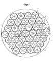
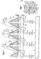
- This grid 1 is made of suitable molded metal or of 3U welded refractory / to reveal cavities 2 with a frustoconical or pyramidal profile widening from the bottom upwards in the thickness of the grid when the latter is arranged horizontally, as it is usual.
- each cavity 2 has an opening 3 which is connected to a pipe 4 for the main distribution of gaseous fluid by channels 5, which are called here the main channels, on each of which is mounted a valve 6.
- the material which constitutes the grid 1 gives rise to a bulge 7 which is traversed from bottom to top by an opening 8.
- a complementary channel 9 which leaves under the grid 1 of a pipe 10 for complementary distribution of gaseous fluid and which rises above the grid 1 and ends in an upper part 11. This is closed at 12 at its top directed upwards and has one where several lateral openings 13.
- the zones 14 defined above are therefore also the zones of action of the complementary channels 9; that is to say the zones where the air blown by the latter causes greater agitation of the parts of the bed which were not very agitated by the gas blown through the main channels 5.
- this exchanger had only one tube 16 which was placed 1 cm above the top 12 of the complementary channels 9.
- the zones 14 may also have large dimensions due to the larger size of the pyramids; the tube 16 can be placed higher.
- the tube or tubes 16 of the exchanger are within a mass of slightly agitated material in the zones 14. The amount of heat evacuated by the tubes 16 is low.
- the quantity of heat evacuated becomes greater as the agitation increases in the zones 14.
- a heat exchanger fluidization device provides great operating flexibility. We go from a step at reduced speed (by blowing through the main channels 5 only) to a step at maximum pace (by blowing through the main channels 5 and the complementary channels 9) while at the same time improving the heat transfer achieved by the exchanger, by simple commissioning of the additional channels 9.
- the apparatus of the invention also gives the possibility of simple regulation beyond combustion temperature within the fluidized bed. If the temperature of the latter drops, by decreasing the air flow through the complementary channels 9, the heat transfer coefficient of the exchanger is reduced and the excess air is reduced, which promotes a rise in the temperature.
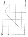
- Figure 4 is a graph which shows the variation of the global exchange coefficient indicated on the ordinate in Watt / m 2 / ° C as a function of the fluidization speed indicated on the abscissa in m / s, with a grid 1 and a tube 16 placed 1 cm above the complementary channels 9.
- the total fluidization air flow was adjusted to different values between 145 and 265 m3N / h, which made it possible to achieve fluidization speeds between 1.1 and 3.8 m / s.
- the air was a flow allowing blowing through the main channels 5 to / a progressively increasing speed of 1.1 to 2 m / s.
- the complementary channels only a minimum technical additional air flow was blown.
- the maximum heat transfer coefficient of the tube 16 will be sought by optimizing the complementary air / total fluidization air ratio.
- the exchange coefficient has a variation curve other than that of FIG. 4.
- the complementary channels 9 there is an area of action of the complementary channels 9 in which it is advantageous to have one or more heat exchange tubes to be able to modify the heat transfer with the bed. fluidized, in particular by acting on the flow rate of the gas blown through the complementary channels.
Landscapes
- Engineering & Computer Science (AREA)
- Chemical & Material Sciences (AREA)
- Mechanical Engineering (AREA)
- Combustion & Propulsion (AREA)
- General Engineering & Computer Science (AREA)
- Organic Chemistry (AREA)
- Chemical Kinetics & Catalysis (AREA)
- Physics & Mathematics (AREA)
- Thermal Sciences (AREA)
- Separation By Low-Temperature Treatments (AREA)
- Fluidized-Bed Combustion And Resonant Combustion (AREA)
- Heat-Exchange Devices With Radiators And Conduit Assemblies (AREA)
- Seeds, Soups, And Other Foods (AREA)
- Physical Or Chemical Processes And Apparatus (AREA)
- Devices And Processes Conducted In The Presence Of Fluids And Solid Particles (AREA)
Priority Applications (1)
| Application Number | Priority Date | Filing Date | Title |
|---|---|---|---|
| AT84400690T ATE21964T1 (de) | 1983-04-07 | 1984-04-06 | Wirbelvorrichtung mit innerem waermetauscher. |
Applications Claiming Priority (2)
| Application Number | Priority Date | Filing Date | Title |
|---|---|---|---|
| FR8305689A FR2543848B1 (fr) | 1983-04-07 | 1983-04-07 | Appareil de fluidisation avec echangeur de chaleur interne |
| FR8305689 | 1983-04-07 |
Publications (2)
| Publication Number | Publication Date |
|---|---|
| EP0123596A1 true EP0123596A1 (de) | 1984-10-31 |
| EP0123596B1 EP0123596B1 (de) | 1986-09-03 |
Family
ID=9287610
Family Applications (1)
| Application Number | Title | Priority Date | Filing Date |
|---|---|---|---|
| EP84400690A Expired EP0123596B1 (de) | 1983-04-07 | 1984-04-06 | Wirbelvorrichtung mit innerem Wärmetauscher |
Country Status (12)
| Country | Link |
|---|---|
| US (1) | US4674564A (de) |
| EP (1) | EP0123596B1 (de) |
| JP (1) | JPS59205587A (de) |
| AT (1) | ATE21964T1 (de) |
| AU (1) | AU573579B2 (de) |
| BR (1) | BR8401589A (de) |
| CA (1) | CA1231092A (de) |
| DE (1) | DE3460599D1 (de) |
| ES (1) | ES286974Y (de) |
| FR (1) | FR2543848B1 (de) |
| IN (1) | IN160350B (de) |
| ZA (1) | ZA842353B (de) |
Cited By (3)
| Publication number | Priority date | Publication date | Assignee | Title |
|---|---|---|---|---|
| EP0236697A1 (de) * | 1986-01-21 | 1987-09-16 | Ishikawajima-Harima Heavy Industries Co., Ltd. | Wirbelschichtfeuerung |
| GB2315433A (en) * | 1996-07-25 | 1998-02-04 | British Coal Corp | Improvements in or relating to fluidised bed systems |
| US7630291B2 (en) | 2003-08-29 | 2009-12-08 | National Institute Of Information And Communications Technology | Transmitter apparatus, receiver apparatus, transmitting method, receiving method, and program |
Families Citing this family (4)
| Publication number | Priority date | Publication date | Assignee | Title |
|---|---|---|---|---|
| US4490517A (en) * | 1983-10-03 | 1984-12-25 | Olin Corporation | Solid TDI residue-dicarboxylic ester binder composition and lignocellulosic composite materials prepared therefrom |
| FR2633196B2 (fr) * | 1987-11-30 | 1991-05-31 | Inst Francais Du Petrole | Appareil pour injecter une charge d'hydrocarbures dans un reacteur |
| FR2624401A1 (fr) * | 1987-12-11 | 1989-06-16 | Charbonnages De France | Grille de fluidisation refroidie |
| FR2635470A1 (fr) * | 1988-08-19 | 1990-02-23 | Charbonnages De France | Dispositif d'alimentation en gaz de fluidisation des ouvertures d'une grille de support d'un lit de particules a fluidiser |
Citations (2)
| Publication number | Priority date | Publication date | Assignee | Title |
|---|---|---|---|---|
| US3908284A (en) * | 1971-09-29 | 1975-09-30 | Ceskoslovenska Akademie Ved | Method of and apparatus for heat transfer in a fluidized bed |
| EP0084492A2 (de) * | 1982-01-20 | 1983-07-27 | Etablissement public dit: CHARBONNAGES DE FRANCE | Ofen und Verfahren zur Behandlung von festen Brennstoffpartikeln in einem Wirbelbett |
Family Cites Families (5)
| Publication number | Priority date | Publication date | Assignee | Title |
|---|---|---|---|---|
| CS148943B1 (de) * | 1970-10-22 | 1973-05-24 | ||
| US4135889A (en) * | 1976-12-20 | 1979-01-23 | University Of Utah | Single stage, coal gasification reactor |
| DE2850536C2 (de) * | 1978-11-22 | 1987-02-05 | Deutsche Babcock Ag, 4200 Oberhausen | Dampferzeuger mit Wirbelschicht-Brennkammer |
| JPS5941770B2 (ja) * | 1979-01-24 | 1984-10-09 | 三菱重工業株式会社 | 流動層装置 |
| DE3019701A1 (de) * | 1980-05-23 | 1981-12-03 | Deutsche Babcock Ag, 4200 Oberhausen | Duese fuer eine wirbelschichtfeuerung |
-
1983
- 1983-04-07 FR FR8305689A patent/FR2543848B1/fr not_active Expired
-
1984
- 1984-03-29 ZA ZA842353A patent/ZA842353B/xx unknown
- 1984-03-31 IN IN225/MAS/84A patent/IN160350B/en unknown
- 1984-04-04 AU AU26403/84A patent/AU573579B2/en not_active Ceased
- 1984-04-05 BR BR8401589A patent/BR8401589A/pt not_active IP Right Cessation
- 1984-04-06 JP JP59067806A patent/JPS59205587A/ja active Pending
- 1984-04-06 AT AT84400690T patent/ATE21964T1/de not_active IP Right Cessation
- 1984-04-06 ES ES1984286974U patent/ES286974Y/es not_active Expired
- 1984-04-06 DE DE8484400690T patent/DE3460599D1/de not_active Expired
- 1984-04-06 EP EP84400690A patent/EP0123596B1/de not_active Expired
- 1984-04-06 CA CA000451458A patent/CA1231092A/fr not_active Expired
-
1986
- 1986-04-17 US US06/854,077 patent/US4674564A/en not_active Expired - Fee Related
Patent Citations (2)
| Publication number | Priority date | Publication date | Assignee | Title |
|---|---|---|---|---|
| US3908284A (en) * | 1971-09-29 | 1975-09-30 | Ceskoslovenska Akademie Ved | Method of and apparatus for heat transfer in a fluidized bed |
| EP0084492A2 (de) * | 1982-01-20 | 1983-07-27 | Etablissement public dit: CHARBONNAGES DE FRANCE | Ofen und Verfahren zur Behandlung von festen Brennstoffpartikeln in einem Wirbelbett |
Cited By (4)
| Publication number | Priority date | Publication date | Assignee | Title |
|---|---|---|---|---|
| EP0236697A1 (de) * | 1986-01-21 | 1987-09-16 | Ishikawajima-Harima Heavy Industries Co., Ltd. | Wirbelschichtfeuerung |
| GB2315433A (en) * | 1996-07-25 | 1998-02-04 | British Coal Corp | Improvements in or relating to fluidised bed systems |
| GB2315433B (en) * | 1996-07-25 | 2000-01-19 | British Coal Corp | Improvements in or relating to fluidised bed systems |
| US7630291B2 (en) | 2003-08-29 | 2009-12-08 | National Institute Of Information And Communications Technology | Transmitter apparatus, receiver apparatus, transmitting method, receiving method, and program |
Also Published As
| Publication number | Publication date |
|---|---|
| ES286974U (es) | 1985-11-16 |
| ATE21964T1 (de) | 1986-09-15 |
| ES286974Y (es) | 1986-06-01 |
| DE3460599D1 (en) | 1986-10-09 |
| JPS59205587A (ja) | 1984-11-21 |
| AU2640384A (en) | 1984-10-11 |
| BR8401589A (pt) | 1984-11-13 |
| IN160350B (de) | 1987-07-04 |
| EP0123596B1 (de) | 1986-09-03 |
| FR2543848A1 (fr) | 1984-10-12 |
| AU573579B2 (en) | 1988-06-16 |
| CA1231092A (fr) | 1988-01-05 |
| US4674564A (en) | 1987-06-23 |
| FR2543848B1 (fr) | 1985-11-29 |
| ZA842353B (en) | 1985-05-29 |
Similar Documents
| Publication | Publication Date | Title |
|---|---|---|
| EP0084492B1 (de) | Ofen und Verfahren zur Behandlung von festen Brennstoffpartikeln in einem Wirbelbett | |
| FR2486223A1 (fr) | Echangeur de chaleur a lit fluidise | |
| FR2704303A3 (fr) | Procédé pour la combustion d'ordures sur une grille de combustion ainsi que grille pour l'exécution du procédé et plaque de grille pour la réalisation d'une pareille grille. | |
| EP0162748B1 (de) | Verfahren und Apparat für die Zirkulation von Feststoffen innerhalb einer Wirbelkammer | |
| EP0123596B1 (de) | Wirbelvorrichtung mit innerem Wärmetauscher | |
| FR2895271A1 (fr) | Organe de deversement d'une enceinte de traitement, notamment d'hydrocarbures, et enceinte correspondant | |
| CH639187A5 (fr) | Chaudiere, notamment pour installation de chauffage. | |
| EP0236647B1 (de) | Wirbelbettwärmeerzeuger mit Mitteln für Aschenbeseitigung und Wärmerückgewinnung | |
| EP0147275B1 (de) | Verbrennungsofen für Wirbelbettkessel | |
| FR2657683A1 (fr) | Ensemble de combustion a separateur de particules incorpore et a lit fluidise. | |
| EP0213980B1 (de) | Verfahren zur Regelung der Wärmeleistung eines Hausmüllverbrennungsofens und Anlage zur Durchführung dieses Verfahrens | |
| EP0009455A1 (de) | Vorrichtung zum Wärmeaustausch zwischen festen Teilchen und einem Gasstrom | |
| FR2896709A1 (fr) | Separateur de solides en particulier pour installation de combustion | |
| FR2542423A1 (fr) | Economiseurs de chaleur | |
| BE892972A (fr) | Appareillage pour l'extraction de produits granules chauds en lit fluidise, tels que les cendres provenant d'un foyer de combustion a lit fluidise. | |
| EP0026150A1 (de) | Feste und auch flüssige Brennstoffe verwendendes Heizgerät | |
| BE439528A (de) | ||
| FR2463898A1 (fr) | Dispositif de recuperation d'energie pour cheminee a feu ouvert | |
| BE505151A (de) | ||
| FR2657951A1 (fr) | Chaudiere et installation de chauffage central et/ou de production d'eau chaude sanitaire. | |
| BE439790A (de) | ||
| FR2488374A1 (fr) | Dispositif de securite pour recuperateur calorifique de cheminee | |
| BE459493A (de) | ||
| BE366170A (de) | ||
| FR2604181A1 (fr) | Dispositif pour la fabrication de charbon de bois en panier-conteneur |
Legal Events
| Date | Code | Title | Description |
|---|---|---|---|
| PUAI | Public reference made under article 153(3) epc to a published international application that has entered the european phase |
Free format text: ORIGINAL CODE: 0009012 |
|
| AK | Designated contracting states |
Designated state(s): AT BE CH DE GB IT LI LU NL SE |
|
| 17P | Request for examination filed |
Effective date: 19850319 |
|
| 17Q | First examination report despatched |
Effective date: 19860117 |
|
| ITF | It: translation for a ep patent filed | ||
| GRAA | (expected) grant |
Free format text: ORIGINAL CODE: 0009210 |
|
| AK | Designated contracting states |
Kind code of ref document: B1 Designated state(s): AT BE CH DE GB IT LI LU NL SE |
|
| PG25 | Lapsed in a contracting state [announced via postgrant information from national office to epo] |
Ref country code: AT Effective date: 19860903 |
|
| REF | Corresponds to: |
Ref document number: 21964 Country of ref document: AT Date of ref document: 19860915 Kind code of ref document: T |
|
| PG25 | Lapsed in a contracting state [announced via postgrant information from national office to epo] |
Ref country code: SE Effective date: 19860930 |
|
| REF | Corresponds to: |
Ref document number: 3460599 Country of ref document: DE Date of ref document: 19861009 |
|
| BECN | Be: change of holder's name |
Effective date: 19860903 |
|
| PG25 | Lapsed in a contracting state [announced via postgrant information from national office to epo] |
Ref country code: LU Free format text: LAPSE BECAUSE OF NON-PAYMENT OF DUE FEES Effective date: 19870430 |
|
| PLBE | No opposition filed within time limit |
Free format text: ORIGINAL CODE: 0009261 |
|
| STAA | Information on the status of an ep patent application or granted ep patent |
Free format text: STATUS: NO OPPOSITION FILED WITHIN TIME LIMIT |
|
| RAP2 | Party data changed (patent owner data changed or rights of a patent transferred) |
Owner name: CHARBONNAGES DE FRANCE, ETABLISSEMENT PUBLIC DITE: |
|
| 26N | No opposition filed | ||
| NLT2 | Nl: modifications (of names), taken from the european patent patent bulletin |
Owner name: ETABLISSEMENT PUBLIC DITE: CHARBONNAGES DE FRANCE |
|
| REG | Reference to a national code |
Ref country code: CH Ref legal event code: PFA Free format text: CHARBONNAGES DE FRANCE |
|
| PGFP | Annual fee paid to national office [announced via postgrant information from national office to epo] |
Ref country code: LU Payment date: 19890331 Year of fee payment: 6 |
|
| PGFP | Annual fee paid to national office [announced via postgrant information from national office to epo] |
Ref country code: CH Payment date: 19890407 Year of fee payment: 6 |
|
| ITTA | It: last paid annual fee | ||
| PGFP | Annual fee paid to national office [announced via postgrant information from national office to epo] |
Ref country code: NL Payment date: 19890430 Year of fee payment: 6 |
|
| PGFP | Annual fee paid to national office [announced via postgrant information from national office to epo] |
Ref country code: GB Payment date: 19900331 Year of fee payment: 7 |
|
| PGFP | Annual fee paid to national office [announced via postgrant information from national office to epo] |
Ref country code: BE Payment date: 19900404 Year of fee payment: 7 |
|
| PG25 | Lapsed in a contracting state [announced via postgrant information from national office to epo] |
Ref country code: LI Effective date: 19900430 Ref country code: CH Effective date: 19900430 |
|
| PGFP | Annual fee paid to national office [announced via postgrant information from national office to epo] |
Ref country code: DE Payment date: 19900430 Year of fee payment: 7 |
|
| PG25 | Lapsed in a contracting state [announced via postgrant information from national office to epo] |
Ref country code: NL Effective date: 19901101 |
|
| NLV4 | Nl: lapsed or anulled due to non-payment of the annual fee | ||
| REG | Reference to a national code |
Ref country code: CH Ref legal event code: PL |
|
| PG25 | Lapsed in a contracting state [announced via postgrant information from national office to epo] |
Ref country code: GB Effective date: 19910406 |
|
| PG25 | Lapsed in a contracting state [announced via postgrant information from national office to epo] |
Ref country code: BE Effective date: 19910430 |
|
| BERE | Be: lapsed |
Owner name: CHARBONNAGES DE FRANCE Effective date: 19910430 |
|
| GBPC | Gb: european patent ceased through non-payment of renewal fee | ||
| PG25 | Lapsed in a contracting state [announced via postgrant information from national office to epo] |
Ref country code: DE Effective date: 19920201 |