EP0123619A2 - Hydraulischer Rotationsverteiler, insbesondere für die Servolenkvorrichtung eines Kraftfahrzeuges - Google Patents
Hydraulischer Rotationsverteiler, insbesondere für die Servolenkvorrichtung eines Kraftfahrzeuges Download PDFInfo
- Publication number
- EP0123619A2 EP0123619A2 EP84400776A EP84400776A EP0123619A2 EP 0123619 A2 EP0123619 A2 EP 0123619A2 EP 84400776 A EP84400776 A EP 84400776A EP 84400776 A EP84400776 A EP 84400776A EP 0123619 A2 EP0123619 A2 EP 0123619A2
- Authority
- EP
- European Patent Office
- Prior art keywords
- elastic device
- primary
- cavity
- elastic
- primary element
- Prior art date
- Legal status (The legal status is an assumption and is not a legal conclusion. Google has not performed a legal analysis and makes no representation as to the accuracy of the status listed.)
- Granted
Links
Images


Classifications
-
- B—PERFORMING OPERATIONS; TRANSPORTING
- B62—LAND VEHICLES FOR TRAVELLING OTHERWISE THAN ON RAILS
- B62D—MOTOR VEHICLES; TRAILERS
- B62D5/00—Power-assisted or power-driven steering
- B62D5/06—Power-assisted or power-driven steering fluid, i.e. using a pressurised fluid for most or all the force required for steering a vehicle
- B62D5/08—Power-assisted or power-driven steering fluid, i.e. using a pressurised fluid for most or all the force required for steering a vehicle characterised by type of steering valve used
- B62D5/083—Rotary valves
-
- Y—GENERAL TAGGING OF NEW TECHNOLOGICAL DEVELOPMENTS; GENERAL TAGGING OF CROSS-SECTIONAL TECHNOLOGIES SPANNING OVER SEVERAL SECTIONS OF THE IPC; TECHNICAL SUBJECTS COVERED BY FORMER USPC CROSS-REFERENCE ART COLLECTIONS [XRACs] AND DIGESTS
- Y10—TECHNICAL SUBJECTS COVERED BY FORMER USPC
- Y10T—TECHNICAL SUBJECTS COVERED BY FORMER US CLASSIFICATION
- Y10T137/00—Fluid handling
- Y10T137/8593—Systems
- Y10T137/86493—Multi-way valve unit
- Y10T137/86574—Supply and exhaust
- Y10T137/86638—Rotary valve
Definitions
- the present invention relates to rotary hydraulic distributors, more particularly for a vehicle power steering system, of the type comprising a primary rotary element, intended to be connected to an actuating device (typically a vehicle steering wheel), a secondary rotary element, coaxial. to the primary rotary element and intended to be connected to a driven mechanism (typically a steering wheel steering mechanism), a valve means coupled to the primary element and intended to control a hydraulic motor assisting the mechanism driven as a function of a limited relative angular displacement between the primary and secondary elements, a part of the secondary element at least partially surrounding a part of the primary element, and at least one deformable elastic device of generally closed substantially annular configuration surrounding at least the primary element at the level of said part of the latter surrounded by the secondary element and having at least one pair of abutment surfaces cooperating with first and second connecting elements connected respectively to the primary and secondary elements to maintain the latter in relative centered position of rest.
- actuating device typically a vehicle steering wheel
- secondary rotary element coaxial. to the primary rotary element
- a hydraulic distributor of this type is the subject of document EP-A-0 077 710. in the name of the applicant, the content of which is supposed to be incorporated here for reference, and which describes the use, as elastic device, of less a C-shaped spring ensuring effective centering in the rest position of the primary and secondary elements, by allowing an elastic coupling with dead travel between these elements and also providing a desirable elastic reaction on the primary element, in particular to provide a tactile "sensation" when this primary element is actuated.
- the prestressing and, consequently, the reaction provided by the C-shaped spring is determined once and for all by dimensioning the spring and / or the associated connecting elements.
- Document PS 1 014 444 thus describes, in place and instead of helical reaction springs, the use of two pistons mounted in opposition in the stator of the valve means and being used to create on the input shaft a antagonistic torque by being connected to the power supply circuits of the assistance motor, in a delicate arrangement, difficult to balance and not modular.
- EP-A-0 021 970 and EP-A-0 084 487 in the name of the application - - resse moreover describe the use of controlled reaction pressure exerted, to create antagonistic couples on the primary or input element of the distributor, on portions of the rotor of the valve means, in this case of the so-called "star" type, in arrangements which are particularly flexible and versatile but of rather delicate manufacture.
- the object of the present invention is to propose a hydraulic distributor of the type defined first, of particularly simple design, of easy manufacture and assembly, of picked up configuration, allowing, with an extremely reduced number of components, to simultaneously ensure elastic centering. , a reaction which is also elastic but can be modified by internal or external means, as well as, for an assisted steering mechanism, the determination - also modular - of a hydraulic central point (or initial reaction).
- the elastic device is mounted for leaktight sliding by its opposite annular lateral faces in an annular cavity formed in a solid part in rotation with the secondary element, concentric with the latter, and is shaped to define in this cavity an internal chamber and a separate external chamber and of inversely variable volumes, and in that it comprises means for conveying a fluid under modular pressure in at least one of these chambers.
- FIG. 6 schematically represents a rotary hydraulic distributor for the vehicle's power steering system.
- the distributor comprises, in a steering box 1, a primary rotary element 2 intended to be connected to an actuating device - in this case a vehicle steering wheel - and a secondary rotary element 3, coaxial with the primary element 2 , extending in the extension thereof and intended to be connected to a driven mechanism - typically a mechanism for orienting directional wheels - the secondary element 3 extending to constitute for example a pinion meshing with a rack of a steering mechanism.
- This rack (not shown) is operatively coupled to an assistance device 10 constituted by a double-acting cylinder comprising two opposing chambers V 1 and V 2 .
- the assistance cylinder 10 is controlled by a distribution valve means constituted, in the example shown, of a star rotor 11 received with sliding in sealed rotation in a discoid cavity complementary to a stator 12 housed in a cavity interior 13 of the housing 1 and constituted by a coaxial assembly of two annular end pieces 14 and 15 and an annular intermediate piece 16 surrounding the rotor 11, these pieces being assembled by bolts 17 parallel to the common axis of the elements primary 2 and secondary 3.
- the star rotor 11 is rotatably united with an end portion 2 'of the primary input element 2.
- Such a star rotor distribution valve means is described in particular in the documents EP-A-0 021 970, EP-A-0 084 487 in the name of the plaintiff, the content of which is assumed to be incorporated here for reference.
- the rotor 11 and the stator 12 mutually define a pair of parallel circuits 18 and 18 'between a source of pressurized fluid S and a discharge D, each circuit 18 or 18' comprising at least two throttles variables in series a, b or a ', b' implemented during the relative movement of the rotor 11 relative to the stator 12 to control the pressure in the chambers V 1 or V 2 of the assistance cylinder 10 (as shown schematically in Figures 14 to 19).
- the present invention relates to an elastic device, generally designated by the reference 4, cooperating with the primary 2 and secondary 3 elements to ensure effective centering in the rest position of these primary and secondary elements (and therefore of the rotor 11 vis-à-vis of the stator 12) by authorizing an elastic coupling with dead travel between these primary and secondary elements while providing on the primary element 2 an elastic reaction for, in the case of power steering, providing the driver with a tactile "feeling" during actuation of the dispenser.
- a part 3 'of the secondary element 3 at least partially surrounds a part 2' of the primary element 2, the deformable elastic device 4 surrounding at least said part 2 'of the primary element.
- the elastic device 4 has a generally annular shape in C, the opposite ends 5 of the branches of C forming a pair of abutment surfaces cooperating, on the one hand with the transversely opposite edges a pin 20 fitted diametrically in part 2 'of the primary element 2, and on the other hand with two projections 30 extending axially towards each other from the axially opposite walls 31 of a annular chamber 32 formed in the part 3 ′ of the secondary element 3 and in which the elastic device 4 is disposed.
- the elastic device 4 is mounted for sliding sliding by its opposite annular lateral faces 40 against the plane, upright, parallel faces 31 of the cavity 32.
- l 'one of the ends of the legs of the elastic device 4 has an extension portion 41 offset radially outward to come to cover in sliding sliding the periphery of the other end of the device 4, the sealing being ensured by a seal 42 carried by either of these end portions overlapping.
- the elastic device 4 delimits in the cavity 32 an internal chamber 6 and an external chamber 7 separated from each other and of inversely variable volumes when the device elas tick 4 undergoes a deformation tending to bring the opposite faces 5 apart or apart.
- a fluid under modular pressure P r can be admitted, in the example shown, into the external chamber 7 via a passage 8 formed in the part 3 ′ of the secondary element 3. It is thus possible, as a function of the pressure P r admitted into the chamber 7, of modifying the elastic characteristic of the device 4 otherwise determined once and for all by its dimensions, and therefore of modulating the reaction provided by this elastic device 4 in particular as a function of parameters related to the driving conditions of the vehicle, the pressure P being itself modulated as a function of these parameters, as will be seen below.
- FIG. 3 The embodiment shown in Figure 3 is similar to that of Figures 1 and 2 except that the elastic device 4 is arranged around the part 3 'of the secondary element 3 being in the form of a tubular extension provided with a first lumen 33 and, symmetrically on either side of the latter, of two lumens 34.
- the cavity 32 housing the elastic device 4 is formed by a part capable of moving in rotation with the element secondary 3, 3 'and constituted for example by an end piece 15 of the stator 12 of the dispensing valve means described above in relation to FIG. 6.
- the facing faces 5 of the ends of the elastic device 4 cooperate with a radial projection 20 'formed in one piece with the part 2' of the primary element and extending freely, at rest, in the first lumen 33 of the part 3 '.
- the elastic device 4 cooperates with this part 3 'by means of projections 44 projecting radially inwards and defining bearing faces 5' cooperating with the edges directed towards the first lumen 33 of the lumens 34 in which the projections 44 are received.
- FIG. 5 is also, in broad outline, similar to those described in relation to FIGS. 2 and 3 except that the end part 41 co-operates overlapping with an extension forming tab extending outwards 43 'from the other end of the elastic device 4.
- the radial projection 20' of the part 2 ' cooperates with the facing bearing faces 5 of the elastic device 4, the second faces of which 'support 5' are constituted by the opposite faoes of the tab 43 'and its equivalent forming the connection with the extension 41, these elements extending freely through a lumen 33 formed in the part 3'.
- two diametrically inverted adjacent elastic devices 4 and 4 ′ are provided, the part 3 ′ being consequently provided with two slots 33 and 33 ′ diametrically opposite one to the other. the other.
- the elastic device 4 is, as in the / arranged around the part 2 'of the primary element 2 inside the part 3' of the secondary element 3 defining the cavity 32.
- the bearing faces 5 of the elastic device 4 are here formed by the opposite edges of two legs 43 projecting inwardly received in a longitudinal slot 20 "of the part 2 'of the primary element.
- support 5 'of the elastic device 4 cooperating with the edges of a lumen of the part 3' of the secondary element 3 are formed by a tab 43 'extending towards the outside of the end of the elastic device 4 covered by the extension 41 of the other end and the corresponding connection face of this extension 41.
- the elastic device 4 is arranged around the part 3 'of the secondary element 3 itself immediately surrounding the end part 2 'of the primary element 2.
- the cavity 32 is formed in the end piece 15 of the stator 12 with which is also associated, by means of the bolts 17, an annular extension 150 defining one of the annular walls 31 of the cavity 32.
- the bearing faces 5 of the elastic device 4 with the part 2 ′ are formed by lugs 43 extending towards :; inside and received in a longitudinal groove 20 ′′ from part 2 ', these tabs 43 also extending through a slot 34 in part 3 ′ to form the bearing faces 5 ′ in the extension of the faces support 5.
- the modulation pressure P is introduced into the internal chamber 6 by passage 8. It will be noted, in FIGS. 6 and 7, that two adjacent diametrically inverted elastic devices 4 and 4 ′ are provided as in the embodiment of FIG. 4.
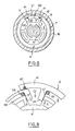
- the rotor 11 of the distribution valve means being coupled in rotation to the end part 2 ′ of the primary element 2, the cooperation between this part 2 * and the elastic device 4 can be carried out as a variant, as shown in Figures 8 and 9 . , by means of one of the arms 110 extending radially outward from the rotor 11.
- the elastic device 4 can be arranged around the rotor 11, inside the intermediate piece annular 16 of the stator, the bearing faces 5 cooperating with the outer edges of the arm 110 and the extensions 41 cooperating in sealed sliding with the outer periphery of the arm 110 advantageously carrying the seals 42.
- the opposite ends of the extensions 41 form the bearing faces 5 t cooperating with the opposite lateral faces of a projection 160 of the part 16 projecting radially inwards; the reaction modulation pressure P r is admitted, through passage 8, into the annular space forming the chamber 7 between the external periphery of the elastic device 4 and the internal periphery of the part 16.
- the bearing faces 5 of the elastic device can be formed by lugs 43 extending towards the inside of the elastic device 4 to cooperate respectively with the outer edges opposite two radial arms 110 adjacent to the rotor 11.
- the edges of the tabs 43 forming the bearing faces 5 also form the bearing faces 5 'cooperating with pins 151 integral with the stator 12 and extending axially between the outer peripheral edges of the arms 110 and the inner surface of the elastic device 4, the reaction modulation pressure P r being admitted, through the passage 8, into the internal chamber 6.
- the elastic device 4 is in the form of a closed annular structure comprising two pairs of internal arms 44 of configuration substantially semicircular, the opposite ends of which form the bearing surfaces 5 (and 5 ') cooperating with the pin 20 passing diametrically on either side of the part 2'. and with the projections 30 of the faces 31 of the cavity 32.
- the internal cavity 6 is thus entirely defined in the elastic device 4, essentially between the arms 44 and the peripheral junction zones 45.
- the reaction modulation pressure P r is admitted by the passage 8 in the external chamber 7 defined in the cavity 32.
- Figures 12 and 13 is similar to that of Figures 1 and 2 except that the elastic device here consists of two symmetrical subsets 4 1 and 4 2 , the extension of one (41 1 or 42 2 ) cooperating in leaktight sliding with the end of the other (4 2 or 4 1 ).
- the assembly and the elastic nature of the device constituted by the two sub-assemblies 4 1 and 4 2 are ensured by diametrically opposed springs 45 each bearing in facing housings formed on the central part of the corresponding sub-assembly and in the internal peripheral face of the part 3 '.
- the modulation pressure P r is introduced, through passage 8, into the external chamber 7.
- Figures 14 to 19 illustrate various block diagrams for providing the modulated reaction pressure P r .
- the reaction pressure P r is taken from a branch 19 between the source S and the discharge D (upstream of the distributor), between two variable throttles d and e actuated simultaneously in opposite direction by an electromagnetic actuator EV itself controlled by signals from the vehicle's on-board computer.
- the upstream throttle d of the bypass 19 is fixed, only the downstream throttle e being modulated by the actuator EV.
- FIG. 16 is identical to that of FIG.
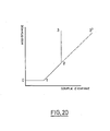
- a pressure limiting valve R with spring calibrated limiting the reaction pressure (and therefore the reaction torque) to a determined maximum value, which corresponds to portion 2-3 of the characteristic in FIG. 20.
- Figures 17 to 19 show other alternative embodiments for further determining the hydraulic center point of the distributor (that is to say the 0-1 portion of the characteristic of Figure 20).
- the reaction pressure P r is taken at the outlet of the distributor (downstream of circuits 18 and 18 1. ), A fixed restriction d being provided in the return line to discharge D.
- the downstream throttle d can be modulated by an electromagnetic actuator EV as in the embodiment of FIG. 15. To eliminate the problem due to the presence of a permanent throttle downstream of the distributor, the latter can be arranged as shown in FIG.
- each parallel circuit 18, 18 ' downstream of the variable throttles a, b or a', b ', a third throttle variable c or e 'also actuated by the primary element 2 of the distributor, the reaction pressure P being taken upstream of the latter.
- the throttles a, b, c and a ', b', c ' are determined so that, in a direction of rotation of the primary element 2, the throttles b and e' come first into play, after which the throttling a comes into play (b 'and c, then a' in the other direction of actuation).
Landscapes
- Engineering & Computer Science (AREA)
- Chemical & Material Sciences (AREA)
- Combustion & Propulsion (AREA)
- Transportation (AREA)
- Mechanical Engineering (AREA)
- Multiple-Way Valves (AREA)
- Power Steering Mechanism (AREA)
Applications Claiming Priority (2)
| Application Number | Priority Date | Filing Date | Title |
|---|---|---|---|
| ES522189 | 1983-04-26 | ||
| ES522189A ES8404474A1 (es) | 1983-04-26 | 1983-04-26 | Perfeccionamientos en distribuidores hidraulicos rotativos. |
Publications (3)
| Publication Number | Publication Date |
|---|---|
| EP0123619A2 true EP0123619A2 (de) | 1984-10-31 |
| EP0123619A3 EP0123619A3 (en) | 1985-10-02 |
| EP0123619B1 EP0123619B1 (de) | 1986-12-10 |
Family
ID=8485694
Family Applications (1)
| Application Number | Title | Priority Date | Filing Date |
|---|---|---|---|
| EP84400776A Expired EP0123619B1 (de) | 1983-04-26 | 1984-04-18 | Hydraulischer Rotationsverteiler, insbesondere für die Servolenkvorrichtung eines Kraftfahrzeuges |
Country Status (7)
| Country | Link |
|---|---|
| US (1) | US4582086A (de) |
| EP (1) | EP0123619B1 (de) |
| JP (1) | JPS59226777A (de) |
| AU (1) | AU558092B2 (de) |
| BR (1) | BR8402015A (de) |
| DE (1) | DE3461617D1 (de) |
| ES (1) | ES8404474A1 (de) |
Cited By (2)
| Publication number | Priority date | Publication date | Assignee | Title |
|---|---|---|---|---|
| EP0509892A1 (de) * | 1991-04-19 | 1992-10-21 | Bendix Espana S.A. | Hydraulisches Drehventil |
| WO1994011646A1 (fr) * | 1992-11-17 | 1994-05-26 | Bendix Espana S.A. | Dispositif elastique de centrage et d'accouplement a course morte de deux organes rotatifs |
Families Citing this family (6)
| Publication number | Priority date | Publication date | Assignee | Title |
|---|---|---|---|---|
| ES8206320A1 (es) * | 1981-10-14 | 1982-08-16 | Bendiberica Sa | Perfeccionamientos en distribuidores hidraulicos rotativos. |
| US4774847A (en) * | 1985-10-21 | 1988-10-04 | Zahnradfabrik Friedrichshafen, Ag. | Mechanism for centering relatively rotative components, particularly in rotary valves |
| US4819545A (en) * | 1987-07-28 | 1989-04-11 | Trw Inc. | Power steering system |
| US4922803A (en) * | 1989-03-17 | 1990-05-08 | Techco Corporation | Four-way valve |
| JPH0752783Y2 (ja) * | 1989-12-18 | 1995-12-06 | ティーアールダブリュエスアイ株式会社 | 動力操向装置の油圧切換機構 |
| US5462132A (en) * | 1995-04-14 | 1995-10-31 | General Motors Corporation | Motor vehicle power steering gear |
Family Cites Families (15)
| Publication number | Priority date | Publication date | Assignee | Title |
|---|---|---|---|---|
| DE1014444B (de) * | 1955-08-03 | 1957-08-22 | Zahnradfabrik Friedrichshafen | Lenkvorrichtung fuer Kraftfahrzeuge mit einer hydraulisch oder pneumatisch wirkendenHilfskraftvorrichtung |
| US3465842A (en) * | 1967-12-29 | 1969-09-09 | Bendix Corp | Power steering mechanism |
| JPS5345571B2 (de) * | 1971-08-26 | 1978-12-07 | ||
| GB1535360A (en) * | 1976-09-22 | 1978-12-13 | Cam Gears Ltd | Steering systems and steering gears therefor |
| GB1591309A (en) * | 1976-11-15 | 1981-06-17 | Cam Gears Ltd | Steering systems and steering gears therefor |
| DE2838789C2 (de) * | 1978-09-06 | 1987-03-12 | Zahnradfabrik Friedrichshafen Ag, 7990 Friedrichshafen | Lenkventil mit geschlossener Mitte zur Beaufschlagung des Stellmotors einer Fahrzeughilfskraftlenkung |
| EP0021970B1 (de) * | 1979-07-02 | 1983-11-23 | Bendiberica S.A. | Steuerventil für ein durch Druckmittel betätigtes System |
| US4428399A (en) * | 1980-09-17 | 1984-01-31 | Jidosha Kiki Co., Ltd. | Power steering apparatus |
| US4458580A (en) * | 1981-03-25 | 1984-07-10 | Jidosha Kiki Co., Ltd. | Power steering apparatus |
| DE3277008D1 (en) * | 1981-06-03 | 1987-09-24 | Trw Cam Gears Ltd | A power assisted steering gear assembly |
| ES8206320A1 (es) * | 1981-10-14 | 1982-08-16 | Bendiberica Sa | Perfeccionamientos en distribuidores hidraulicos rotativos. |
| GB2109757B (en) * | 1981-11-18 | 1985-06-19 | Cam Gears Ltd | A power assisted steering gear |
| GB2109756B (en) * | 1981-11-18 | 1985-02-06 | Cam Gears Ltd | Power assisted steering gear |
| ES509159A0 (es) * | 1982-01-14 | 1983-02-01 | Bendiberica Sa | Perfeccionamientos en distribuidores hidraulicos para servomecanismos. |
| JPS58156458A (ja) * | 1982-03-15 | 1983-09-17 | Jidosha Kiki Co Ltd | 動力舵取装置 |
-
1983
- 1983-04-26 ES ES522189A patent/ES8404474A1/es not_active Expired
-
1984
- 1984-04-18 EP EP84400776A patent/EP0123619B1/de not_active Expired
- 1984-04-18 DE DE8484400776T patent/DE3461617D1/de not_active Expired
- 1984-04-23 US US06/602,855 patent/US4582086A/en not_active Expired - Fee Related
- 1984-04-24 AU AU27230/84A patent/AU558092B2/en not_active Ceased
- 1984-04-25 JP JP59082133A patent/JPS59226777A/ja active Granted
- 1984-04-26 BR BR8402015A patent/BR8402015A/pt not_active IP Right Cessation
Cited By (2)
| Publication number | Priority date | Publication date | Assignee | Title |
|---|---|---|---|---|
| EP0509892A1 (de) * | 1991-04-19 | 1992-10-21 | Bendix Espana S.A. | Hydraulisches Drehventil |
| WO1994011646A1 (fr) * | 1992-11-17 | 1994-05-26 | Bendix Espana S.A. | Dispositif elastique de centrage et d'accouplement a course morte de deux organes rotatifs |
Also Published As
| Publication number | Publication date |
|---|---|
| DE3461617D1 (en) | 1987-01-22 |
| US4582086A (en) | 1986-04-15 |
| AU2723084A (en) | 1984-11-01 |
| EP0123619B1 (de) | 1986-12-10 |
| EP0123619A3 (en) | 1985-10-02 |
| JPH0570035B2 (de) | 1993-10-04 |
| JPS59226777A (ja) | 1984-12-19 |
| ES522189A0 (es) | 1984-05-01 |
| BR8402015A (pt) | 1984-12-04 |
| ES8404474A1 (es) | 1984-05-01 |
| AU558092B2 (en) | 1987-01-15 |
Similar Documents
| Publication | Publication Date | Title |
|---|---|---|
| EP0008252B1 (de) | Rotierender hydraulischer Verteiler, insbesondere für hilfskraftverstärkte Lenkungen | |
| EP0272176A1 (de) | Hydraulischer Drehflügelantrieb, insbesondere für einen Flugzeugruderantrieb | |
| EP0072311B1 (de) | Hydraulischer Verteiler für Servomotor mit Zurückbringung in Ruhestellung | |
| EP0123619B1 (de) | Hydraulischer Rotationsverteiler, insbesondere für die Servolenkvorrichtung eines Kraftfahrzeuges | |
| EP0072731B1 (de) | Hydraulischer Verteiler mit Rückwirkung auf die Steuereinrichtung | |
| EP0066507B1 (de) | Hydraulischer Rotationsverteiler für eine hydraulische Antriebseinrichtung | |
| EP0145546B1 (de) | Hydraulischer Verteiler für eine Servoeinrichtung mit Rückwirkung auf das Eingangsglied | |
| EP0509866B1 (de) | Pneumatischer Servomotor | |
| EP0007847B1 (de) | Rotierender hydraulischer Verteiler, insbesondere für hilfskraftverstärkte Lenkungen | |
| EP0132199B1 (de) | Hydraulischer Verteiler für die Steuerung eines Luftfahzeuges | |
| FR2744502A1 (fr) | Joint de transmission homocinetique a billes | |
| EP0112209B1 (de) | Hydraulischer Verteiler für eine Servoeinrichtung mit begrenzter Reaktion auf das Eingangsglied | |
| EP0577499B1 (de) | Lenkstockschalter, insbesondere für Kraftfahrzeuge | |
| WO2019207252A1 (fr) | Agencement hydraulique pour une roue directrice d'un vehicule | |
| EP0075518B1 (de) | Antriebsmechanismus mit Fluidumhilfe, insbesondere für Servolenkungssystem | |
| EP0119923A1 (de) | Servolenkung mit zentralem Abtrieb | |
| EP0095415B1 (de) | Rotationshydraulischer Verteiler mit sternförmigem Rotor, insbesondere für Servolenkungsmechanismus | |
| EP0072712B1 (de) | Hydraulischer Rotationsverteiler für Servomechanismus | |
| EP0181797A1 (de) | Drehbeweglicher Hydraulikverteiler, insbesondere für Servolenkvorrichtung | |
| EP0291608B1 (de) | Trag- und Dichtungseinheit eines ersten Elementes, das sich in einem zweiten Element dreht | |
| EP0999964B1 (de) | Pneumatischer kraftverstärker mit steuerkammer | |
| EP0166657B1 (de) | Kompakter Servolenkungsmechanismus | |
| EP0136233B1 (de) | Kompakt-Servolenkungs-Mechanismus für Kraftfahrzeug | |
| EP0626044B1 (de) | Federnde zentriervorrichtung und totgang-kupplung fuer zwei drehbewegliche teile | |
| EP0075519A2 (de) | Antriebsmechanismus mit Fluidhilfe, insbesondere für Kraftfahrzeugservolenkungssystem |
Legal Events
| Date | Code | Title | Description |
|---|---|---|---|
| PUAI | Public reference made under article 153(3) epc to a published international application that has entered the european phase |
Free format text: ORIGINAL CODE: 0009012 |
|
| 17P | Request for examination filed |
Effective date: 19840509 |
|
| AK | Designated contracting states |
Designated state(s): DE FR GB IT |
|
| PUAL | Search report despatched |
Free format text: ORIGINAL CODE: 0009013 |
|
| AK | Designated contracting states |
Designated state(s): DE FR GB IT |
|
| 17Q | First examination report despatched |
Effective date: 19860527 |
|
| RAP1 | Party data changed (applicant data changed or rights of an application transferred) |
Owner name: BENDIX ESPANA S.A. |
|
| ITF | It: translation for a ep patent filed | ||
| GRAA | (expected) grant |
Free format text: ORIGINAL CODE: 0009210 |
|
| AK | Designated contracting states |
Kind code of ref document: B1 Designated state(s): DE FR GB IT |
|
| REF | Corresponds to: |
Ref document number: 3461617 Country of ref document: DE Date of ref document: 19870122 |
|
| PLBE | No opposition filed within time limit |
Free format text: ORIGINAL CODE: 0009261 |
|
| STAA | Information on the status of an ep patent application or granted ep patent |
Free format text: STATUS: NO OPPOSITION FILED WITHIN TIME LIMIT |
|
| 26N | No opposition filed | ||
| ITTA | It: last paid annual fee | ||
| PGFP | Annual fee paid to national office [announced via postgrant information from national office to epo] |
Ref country code: GB Payment date: 19960409 Year of fee payment: 13 |
|
| PGFP | Annual fee paid to national office [announced via postgrant information from national office to epo] |
Ref country code: FR Payment date: 19960423 Year of fee payment: 13 |
|
| PG25 | Lapsed in a contracting state [announced via postgrant information from national office to epo] |
Ref country code: GB Effective date: 19970418 |
|
| GBPC | Gb: european patent ceased through non-payment of renewal fee |
Effective date: 19970418 |
|
| PG25 | Lapsed in a contracting state [announced via postgrant information from national office to epo] |
Ref country code: FR Free format text: LAPSE BECAUSE OF NON-PAYMENT OF DUE FEES Effective date: 19971231 |
|
| REG | Reference to a national code |
Ref country code: FR Ref legal event code: ST |
|
| PGFP | Annual fee paid to national office [announced via postgrant information from national office to epo] |
Ref country code: DE Payment date: 20000427 Year of fee payment: 17 |
|
| PG25 | Lapsed in a contracting state [announced via postgrant information from national office to epo] |
Ref country code: DE Free format text: LAPSE BECAUSE OF NON-PAYMENT OF DUE FEES Effective date: 20020201 |