EP0123622A2 - Dispositif d'ancrage pour câble de précontrainte - Google Patents
Dispositif d'ancrage pour câble de précontrainte Download PDFInfo
- Publication number
- EP0123622A2 EP0123622A2 EP84400800A EP84400800A EP0123622A2 EP 0123622 A2 EP0123622 A2 EP 0123622A2 EP 84400800 A EP84400800 A EP 84400800A EP 84400800 A EP84400800 A EP 84400800A EP 0123622 A2 EP0123622 A2 EP 0123622A2
- Authority
- EP
- European Patent Office
- Prior art keywords
- block
- plate
- holes
- anchoring device
- cable
- Prior art date
- Legal status (The legal status is an assumption and is not a legal conclusion. Google has not performed a legal analysis and makes no representation as to the accuracy of the status listed.)
- Granted
Links
Images
Classifications
-
- E—FIXED CONSTRUCTIONS
- E04—BUILDING
- E04C—STRUCTURAL ELEMENTS; BUILDING MATERIALS
- E04C5/00—Reinforcing elements, e.g. for concrete; Auxiliary elements therefor
- E04C5/08—Members specially adapted to be used in prestressed constructions
- E04C5/12—Anchoring devices
- E04C5/122—Anchoring devices the tensile members are anchored by wedge-action
-
- Y—GENERAL TAGGING OF NEW TECHNOLOGICAL DEVELOPMENTS; GENERAL TAGGING OF CROSS-SECTIONAL TECHNOLOGIES SPANNING OVER SEVERAL SECTIONS OF THE IPC; TECHNICAL SUBJECTS COVERED BY FORMER USPC CROSS-REFERENCE ART COLLECTIONS [XRACs] AND DIGESTS
- Y10—TECHNICAL SUBJECTS COVERED BY FORMER USPC
- Y10T—TECHNICAL SUBJECTS COVERED BY FORMER US CLASSIFICATION
- Y10T24/00—Buckles, buttons, clasps, etc.
- Y10T24/39—Cord and rope holders
- Y10T24/3907—Sheathed strand
Definitions
- the invention relates to anchoring devices intended for prestressing cables composed of several wires or strands, devices comprising a support plate, an anchoring block pierced with frustoconical holes each traversed by a wire or strand of the cable, said block resting on the support plate, and frustoconical jaws adapted to wedge the wires or strands in the corresponding holes of the block.
- the support plate is hollowed out by a single central opening traversed by all of the wires or strands constituting the cable.
- the edge of this opening, furthest from the block, is connected by a trumpet to the end of the sheath which envelops the cable.
- the block must then have on the one hand a relatively large thickness to resist the flexions to which it is stressed by the tension exerted on the cable, given the vacuum created by the opening of the plate, and on the other hand sufficient transverse dimensions to be able to take press on the edge of this opening.
- said thickness of the block is not solely determined by the dimensions of the jaws.
- the support plate is pierced with multiple holes extending those of the block so that. this plate can support this block over its entire undrilled surface.
- the support plate is no longer pierced with a single central opening, but with a multitude of holes, in the manner of a grid or plate "crosslinked” or gridded.
- This arrangement makes it possible to reduce all the dimensions of the anchoring block, and in particular its thickness, and therefore its cost.
- the conicity of the jaws receiving holes is extended axially beyond the block, in the plate itself, which allows the ends of the jaws to also penetrate into the plate, thus ensuring excellent attachment transverse of these two parts: one is thus sure of the stability over time of their relative transverse positioning.
- the mutual adhesion between the plate and the block can be improved by subjecting appropriate finishing treatments to the facing surfaces of these two parts or by applying to at least one of these surfaces an appropriate coating.
- the block can be welded to the plate.
- the anchoring device shown in Figure 1 comprises a plate 1 pierced with a multitude of cylin holes bricks 1 1 suitable for extending the different frustoconical holes 2 1 hollowed out in an anchoring block 2 itself constituted by a flat paving stone of relatively small dimensions.
- frustoconical jaws 3 block the multiple wires or strands 4 making up the cable to be anchored.
- the periphery of the face, of the plate 1, the most distant from the block 2, is connected, by a trumpet 5 whose diameter decreases away from the plate, at the end of a sheath 6 constituting the envelope of the cable, the sections, wires or strands 4, leaving the plate 1 being guided to said end by said trumpet which surrounds them.
- This trumpet 5 and the sheath 6 are intended to be embedded in the concrete structure 7 which it is desired to subject to prestressing by the tension of the cable.
- the axes of the holes 1 and 2 1 may be divergent towards the outside of the structure 7, as is usual.
- these axes are perpendicular to the support plane of the plate 1, that is to say parallel to the general axis of the cable: the holes which must be made in the plate 1 and in block 2 to obtain the holes 1 1 and 2 1 are then simplified.
- the axes considered could also have a general orientation converging towards the outside of the structure 7, as shown schematically by the angle a.
- the holes hollowed out in the plate 1 each include a frustoconical section 1 3 extending exactly a frustoconical hole 2 1 of the block 2 and the small base of this frustoconical section 1. 2 is connected to a cylindrical section 1 3 emerging outside the plate on its face furthest from block 2.
- the small diameter ends of the jaws 3 can penetrate into the frustoconical sections 1 2 ' which ensures excellent trans securing between the plate 1 and the block 2, making it impossible for them to slide relative in particular to their work in mutual bending.
Landscapes
- Engineering & Computer Science (AREA)
- Architecture (AREA)
- Civil Engineering (AREA)
- Structural Engineering (AREA)
- Piles And Underground Anchors (AREA)
- Bridges Or Land Bridges (AREA)
- Ropes Or Cables (AREA)
- Coating With Molten Metal (AREA)
- Laying Of Electric Cables Or Lines Outside (AREA)
- Surgical Instruments (AREA)
- Reinforcement Elements For Buildings (AREA)
- Diaphragms For Electromechanical Transducers (AREA)
- Laminated Bodies (AREA)
- Electrical Discharge Machining, Electrochemical Machining, And Combined Machining (AREA)
- Installation Of Indoor Wiring (AREA)
Abstract
Description
- L'invention concerne les dispositifs d'ancrage destinés aux câbles de précontrainte composés de plusieurs fils ou torons, dispositifs comportant une plaque d'appui, un bloc d'ancrage percé de trous tronconiques traversés chacun par un fil ou toron du câble, ledit bloc reposant sur la plaque d'appui, et des mors tronconiques propres à coincer les fils ou torons dans les trous correspondants du bloc.
- Dans les modes de réalisation connus de ces dispositifs, la plaque d'appui est évidée par une ouverture centrale unique traversée par la totalité des fils ou torons constitutifs du câble. Le bord, de cette ouverture, le plus éloigné du bloc, est raccordé par une trompette à l'extrémité de la gaine qui enveloppe le câble.
- Le bloc doit alors présenter d'une part une épaisseur relativement grande pour résister aux flexions auxquelles il est sollicité par la tension exercée sur le câble, vu le vide créé par l'ouverture de la plaque, et d'autre part des dimensionstransversalessuffisantespour pouvoir prendre appui sur le bord de cette ouverture. En particulier ladite épaisseur du bloc n'est pas uniquement déterminée par les dimensions des mors.
- Pour remédier à ces inconvénients, conformément à l'invention la plaque d'appui est percée de trous multiples prolongeant ceux du bloc de façon que. cette plaque puisse soutenir ce bloc sur toute sa surface non percée.
- En d'autres termes, la plaque d'appui n'est plus percée d'une ouverture centrale unique, mais d'une multitude de trous, à la façon d'une grille ou plaque "réticulée" ou quadrillée.
- C'est alors l'ensemble de la plaque et du bloc intimement juxtaposés l'une contre l'autre qui résiste aux flexions auxquelles est sollicité le dispositif d'ancrage.
- Cette disposition permet de réduire toutes les dimensions du bloc d'ancrage, et en particulier son épaisseur, et donc son coût.
- On peut bien entendu jouer sur les épaisseurs et natures respectives de la plaque et du bloc en fonction des besoins.
- Selon une disposition avantageuse, la conicité des -― trous de réception des mors est prolongée axialement au-delà du bloc, dans la plaque elle-même, ce qui permet aux extrémités des mors de pénétrer également dans la plaque, assurant ainsi une excellente solidarisation transversale de ces deux pièces : on est sûr ainsi de la stabilité dans le temps de leur positionnement transversal relatif.
- Dans le même but on peut améliorer l'adhérence mutuelle entre la plaque et le bloc en faisant subir des traitements de finition appropriés aux surfaces en regard de ces deux pièces ou en appliquant sur l'une au moins de ces surfaces un revêtement approprié.
- Selon une variante, on peut souder le bloc sur la plaque.
- Selon une autre variante on peut même constituer en une seule pièce l'ensemble du bloc et de la plaque, ce qui permet de réaliser par fonderie le corps unique résultant, évidé de ses trous évasés vers l'extérieur.
- Le dessin montre à titre purement illustratif deux modes de réalisation de l'invention.
-
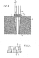
- La figure 1, de ce dessin, montre en coupe axiale un dispositif d'ancrage de câble conforme à l'invention.
- La figure 2 montre également en coupe axiale le détail d'une variante d'un tel dispositif également conforme à l'invention.
- Le dispositif d'ancrage représenté sur la figure 1. comprend une plaque 1 percée d'une multitude de trous cylindriques 11 propres à prolonger les différents trous tronconiques 21 évidés dans un bloc d'ancrage 2 lui-même constitué par un pavé plat de dimensions relativement petites.
- C'est dans les trous 21 que des mors tronconiques 3 bloquent les fils ou torons multiples 4 composant le câble à ancrer.
- La périphérie de la face, de la plaque 1, la plus éloignée du bloc 2, est raccordée, par une trompette 5 dont le diamètre diminue en s'éloignant de la plaque, à l'extrémité d'une gaine 6 constituant l'enveloppe du câble, les tronçons, des fils ou torons 4, sortant de la plaque 1 étant guidés jusqu'à ladite extrémité par ladite trompette qui les entoure. Cette trompette 5 et la gaine 6 sont destinées à être noyées dans l'ouvrage en béton 7 que l'on désire soumettre à la précontrainte par la tension du câble.
- C'est alors sur cet ouvrage 7 que prend appui la périphérie de la plaque d'appui 1.
- Les axes des trous 1 et 21 peuvent être divergents vers l'extérieur de l'ouvrage 7, comme il est habituel.
- Mais dans le mode de réalisation préféré illustré, ces axes sont perpendiculaires au plan d'appui de la plaque 1, c'est-à-dire parallèles à l'axe général du câble : les perçages qui doivent être pratiqués dans la plaque 1 et dans le bloc 2 pour obtenir 1es trous 11 et 21 sont alors simplifiés.
- Les axes considérés pourraient également présenter une orientation générale convergente vers l'extérieur de l'ouvrage 7, comme schématisé par l'angle a.
- Dans la variante de la figure 2, les trous évidés dans la plaque 1 comprennent chacun un tronçon tronconique 13 prolongeant exactement un trou tronconique 21 du bloc 2 et la petite base de ce tronçon tronconique 1.2 est raccordée à un tronçon cylindrique 13 débouchant à l'extérieur de la plaque sur sa face la plus éloignée du bloc 2.
- Avec une telle variante, les extrémités de petit diamètre des mors 3 peuvent pénétrer dans les tronçons tronconiques 12' ce qui assure une excellente solidarisation transversale entre la plaque 1 et le bloc 2, rendant impossible leur glissement relatif à l'occasion notamment de leur travail en flexion mutuel.
Claims (6)
Priority Applications (1)
| Application Number | Priority Date | Filing Date | Title |
|---|---|---|---|
| AT84400800T ATE35011T1 (de) | 1983-04-22 | 1984-04-19 | Vorrichtung zur verankerung eines vorspannkabels. |
Applications Claiming Priority (2)
| Application Number | Priority Date | Filing Date | Title |
|---|---|---|---|
| BR8302084A BR8302084A (pt) | 1983-04-22 | 1983-04-22 | Conjunto para ancoragem de membros tensores |
| BR8302084 | 1983-04-22 |
Publications (3)
| Publication Number | Publication Date |
|---|---|
| EP0123622A2 true EP0123622A2 (fr) | 1984-10-31 |
| EP0123622A3 EP0123622A3 (en) | 1985-08-28 |
| EP0123622B1 EP0123622B1 (fr) | 1988-06-08 |
Family
ID=4033101
Family Applications (1)
| Application Number | Title | Priority Date | Filing Date |
|---|---|---|---|
| EP84400800A Expired EP0123622B1 (fr) | 1983-04-22 | 1984-04-19 | Dispositif d'ancrage pour câble de précontrainte |
Country Status (8)
| Country | Link |
|---|---|
| US (1) | US4558547A (fr) |
| EP (1) | EP0123622B1 (fr) |
| JP (1) | JPS6084909A (fr) |
| AT (1) | ATE35011T1 (fr) |
| BR (1) | BR8302084A (fr) |
| DE (1) | DE3471965D1 (fr) |
| ES (1) | ES8502196A1 (fr) |
| FR (1) | FR2544769B1 (fr) |
Cited By (1)
| Publication number | Priority date | Publication date | Assignee | Title |
|---|---|---|---|---|
| EP1676213A4 (fr) * | 2003-08-01 | 2009-12-30 | Microsoft Corp | Mise en antememoire eparse pour transmission multimedia en continu |
Families Citing this family (7)
| Publication number | Priority date | Publication date | Assignee | Title |
|---|---|---|---|---|
| FR2663975B1 (fr) * | 1990-06-29 | 1993-07-09 | Freyssinet Int Stup | Perfectionnements aux ponts a haubans et plus particulierement a leurs pylones et haubans. |
| US5596854A (en) * | 1994-01-19 | 1997-01-28 | Vsl International Ag | Post-tensioning anchor head assembly |
| DE19539748A1 (de) * | 1995-10-26 | 1997-04-30 | Dyckerhoff & Widmann Ag | Spannbetonbauteil |
| US20040159058A1 (en) * | 2003-02-19 | 2004-08-19 | Jacques Gulbenkian | Unbonded post-tensioning system |
| US7597505B2 (en) * | 2006-03-28 | 2009-10-06 | Price Herbert S | Roof bolt plate |
| CN110034525A (zh) * | 2019-03-28 | 2019-07-19 | 合肥工业大学 | 压力容器传感器引出导线密封装置及方法 |
| CN111485679A (zh) * | 2020-05-07 | 2020-08-04 | 吴立新 | 一种用于扁锚的钢绞线连接器及使用方法 |
Family Cites Families (11)
| Publication number | Priority date | Publication date | Assignee | Title |
|---|---|---|---|---|
| GB647378A (en) * | 1948-09-03 | 1950-12-13 | Dowsett Engineering Constructi | Method and apparatus for use in the manufacture of reinforced concrete |
| DE969806C (de) * | 1952-11-26 | 1958-07-17 | Hochtief Ag Hoch Tiefbauten | Verfahren zum Verkeilen gespannter Drahtbuendel bei der Herstellung von Spannbeton |
| US3060639A (en) * | 1958-12-05 | 1962-10-30 | Prescon Corp | Prestressing apparatus |
| US3226934A (en) * | 1961-05-16 | 1966-01-04 | C I M Consultants Ltd | Rock bolts |
| CH444441A (de) * | 1965-09-16 | 1967-09-30 | Losinger Ag | Einrichtung zum Spannen und Verankern von mehreren, zusammen ein Spannkabel bildenden Spanngliedern |
| DE6938088U (de) * | 1969-09-29 | 1970-01-02 | Ilseder Huette | Spannstahlverankerung |
| CH534786A (de) * | 1971-10-21 | 1973-03-15 | Brandestini Antonio | Einrichtung zum Spannen und Verankern von Drähten oder Litzen |
| JPS5321749Y2 (fr) * | 1972-01-17 | 1978-06-07 | ||
| GB1478308A (en) * | 1973-08-23 | 1977-06-29 | Ccl Systems Ltd | Anchorage assembly for use in the prestressing of concrete structures |
| JPS532313U (fr) * | 1976-06-22 | 1978-01-11 | ||
| JPS5321752U (fr) * | 1976-07-30 | 1978-02-23 |
-
1983
- 1983-04-22 BR BR8302084A patent/BR8302084A/pt not_active IP Right Cessation
-
1984
- 1984-04-18 ES ES84532162A patent/ES8502196A1/es not_active Expired
- 1984-04-19 AT AT84400800T patent/ATE35011T1/de not_active IP Right Cessation
- 1984-04-19 EP EP84400800A patent/EP0123622B1/fr not_active Expired
- 1984-04-19 DE DE8484400800T patent/DE3471965D1/de not_active Expired
- 1984-04-20 FR FR8406348A patent/FR2544769B1/fr not_active Expired
- 1984-04-20 JP JP59080004A patent/JPS6084909A/ja active Pending
- 1984-04-20 US US06/602,464 patent/US4558547A/en not_active Expired - Fee Related
Cited By (1)
| Publication number | Priority date | Publication date | Assignee | Title |
|---|---|---|---|---|
| EP1676213A4 (fr) * | 2003-08-01 | 2009-12-30 | Microsoft Corp | Mise en antememoire eparse pour transmission multimedia en continu |
Also Published As
| Publication number | Publication date |
|---|---|
| EP0123622A3 (en) | 1985-08-28 |
| EP0123622B1 (fr) | 1988-06-08 |
| BR8302084A (pt) | 1984-11-20 |
| DE3471965D1 (en) | 1988-07-14 |
| ATE35011T1 (de) | 1988-06-15 |
| US4558547A (en) | 1985-12-17 |
| FR2544769B1 (fr) | 1986-12-26 |
| ES532162A0 (es) | 1985-01-01 |
| JPS6084909A (ja) | 1985-05-14 |
| ES8502196A1 (es) | 1985-01-01 |
| FR2544769A1 (fr) | 1984-10-26 |
Similar Documents
| Publication | Publication Date | Title |
|---|---|---|
| EP1131512B1 (fr) | Dispositif d'ancrage pour fixer un cable de structure a un element de construction | |
| EP0123622B1 (fr) | Dispositif d'ancrage pour câble de précontrainte | |
| FR2781535A1 (fr) | Dispositif d'assemblage de membrures de charpente metallique en treillis | |
| CA2340010C (fr) | Piece monobloc pour la realisation d'un mors d'ancrage de cable, et procede de fabrication d'un tel mors | |
| EP0465303B1 (fr) | Perfectionnements aux ponts à haubans et plus particulièrement à leurs pylônes et haubans | |
| FR2640301A1 (fr) | Dispositif pour la liaison de poutres de constructions prefabriquees en treillis | |
| EP0254309A1 (fr) | Dispositif de maintien multiple notamment pour des faisceaux de fils dans un central téléphonique | |
| EP0260163B1 (fr) | Perfectionnements aux dispositifs d'ancrage des armatures tendues | |
| FR2824603A1 (fr) | Dispositif de serrage | |
| FR2745600A1 (fr) | Ensemble pour la construction d'une piscine hors sol | |
| EP1108276A1 (fr) | Dispositif de guidage modulaire | |
| FR2764920A1 (fr) | Noeud d'assemblage pour echafaudages tubulaires ou analogues, quelle que soit l'utilisation de ces echafaudages | |
| FR2517770A1 (fr) | Piece d'assemblage pour charpente en bois | |
| FR2738959A1 (fr) | Boite de raccordement pour un reseau de donnees | |
| EP0596103A1 (fr) | Dispositif de couplage mecanique et electrique pour une installation a tres basse tension | |
| FR2574838A1 (fr) | Perfectionnements apportes aux poutres en i essentiellement constituees en bois | |
| FR2718572A1 (fr) | Connecteur électrique à cheville expansible pour fixation sur un support métallique. | |
| FR2484584A1 (fr) | Dispositif de serrage pour cable de haubanage a plusieurs torons | |
| FR2612031A1 (fr) | Dispositif de passage de fils conducteurs et repartiteur telephonique comportant un tel dispositif | |
| FR2678439A3 (fr) | Càble électrique à conducteurs polygonaux | |
| EP0338924A1 (fr) | Perfectionnements aux dispositifs d'ancrage des câbles | |
| BE679919A (fr) | ||
| FR2568911A1 (fr) | Piece de liaison ou connecteur pour la liaison du beton et du metal dans une structure mixte beton-metal et structure mixte equipee d'au moins un tel connecteur | |
| FR2481987A1 (fr) | Dispositif pour l'assemblage de poutres en bois | |
| FR3164918A1 (fr) | Ensemble de construction permettant l’assemblage de jouets |
Legal Events
| Date | Code | Title | Description |
|---|---|---|---|
| PUAI | Public reference made under article 153(3) epc to a published international application that has entered the european phase |
Free format text: ORIGINAL CODE: 0009012 |
|
| AK | Designated contracting states |
Designated state(s): AT BE CH DE GB IT LI NL SE |
|
| PUAL | Search report despatched |
Free format text: ORIGINAL CODE: 0009013 |
|
| AK | Designated contracting states |
Designated state(s): AT BE CH DE GB IT LI NL SE |
|
| 17P | Request for examination filed |
Effective date: 19851028 |
|
| 17Q | First examination report despatched |
Effective date: 19870525 |
|
| RAP1 | Party data changed (applicant data changed or rights of an application transferred) |
Owner name: FREYSSINET INTERNATIONAL (STUP) |
|
| GRAA | (expected) grant |
Free format text: ORIGINAL CODE: 0009210 |
|
| AK | Designated contracting states |
Kind code of ref document: B1 Designated state(s): AT BE CH DE GB IT LI NL SE |
|
| REF | Corresponds to: |
Ref document number: 35011 Country of ref document: AT Date of ref document: 19880615 Kind code of ref document: T |
|
| ITF | It: translation for a ep patent filed | ||
| REF | Corresponds to: |
Ref document number: 3471965 Country of ref document: DE Date of ref document: 19880714 |
|
| GBT | Gb: translation of ep patent filed (gb section 77(6)(a)/1977) | ||
| PLBE | No opposition filed within time limit |
Free format text: ORIGINAL CODE: 0009261 |
|
| STAA | Information on the status of an ep patent application or granted ep patent |
Free format text: STATUS: NO OPPOSITION FILED WITHIN TIME LIMIT |
|
| 26N | No opposition filed | ||
| PGFP | Annual fee paid to national office [announced via postgrant information from national office to epo] |
Ref country code: AT Payment date: 19930326 Year of fee payment: 10 |
|
| PGFP | Annual fee paid to national office [announced via postgrant information from national office to epo] |
Ref country code: GB Payment date: 19930413 Year of fee payment: 10 |
|
| PGFP | Annual fee paid to national office [announced via postgrant information from national office to epo] |
Ref country code: CH Payment date: 19930419 Year of fee payment: 10 |
|
| PGFP | Annual fee paid to national office [announced via postgrant information from national office to epo] |
Ref country code: SE Payment date: 19930426 Year of fee payment: 10 |
|
| PGFP | Annual fee paid to national office [announced via postgrant information from national office to epo] |
Ref country code: DE Payment date: 19930428 Year of fee payment: 10 |
|
| ITTA | It: last paid annual fee | ||
| PGFP | Annual fee paid to national office [announced via postgrant information from national office to epo] |
Ref country code: NL Payment date: 19930430 Year of fee payment: 10 |
|
| PGFP | Annual fee paid to national office [announced via postgrant information from national office to epo] |
Ref country code: BE Payment date: 19930513 Year of fee payment: 10 |
|
| PG25 | Lapsed in a contracting state [announced via postgrant information from national office to epo] |
Ref country code: GB Effective date: 19940419 Ref country code: AT Effective date: 19940419 |
|
| PG25 | Lapsed in a contracting state [announced via postgrant information from national office to epo] |
Ref country code: SE Effective date: 19940420 |
|
| PG25 | Lapsed in a contracting state [announced via postgrant information from national office to epo] |
Ref country code: LI Effective date: 19940430 Ref country code: CH Effective date: 19940430 Ref country code: BE Effective date: 19940430 |
|
| BERE | Be: lapsed |
Owner name: FREYSSINET INTERNATIONAL STUP Effective date: 19940430 |
|
| PG25 | Lapsed in a contracting state [announced via postgrant information from national office to epo] |
Ref country code: NL Effective date: 19941101 |
|
| GBPC | Gb: european patent ceased through non-payment of renewal fee |
Effective date: 19940419 |
|
| NLV4 | Nl: lapsed or anulled due to non-payment of the annual fee | ||
| REG | Reference to a national code |
Ref country code: CH Ref legal event code: PL |
|
| PG25 | Lapsed in a contracting state [announced via postgrant information from national office to epo] |
Ref country code: DE Effective date: 19950103 |
|
| EUG | Se: european patent has lapsed |
Ref document number: 84400800.3 Effective date: 19941110 |