EP0123643A2 - Procédé de commande d'une grandeur de sortie au moyen d'un rapport cyclique - Google Patents
Procédé de commande d'une grandeur de sortie au moyen d'un rapport cyclique Download PDFInfo
- Publication number
- EP0123643A2 EP0123643A2 EP84730025A EP84730025A EP0123643A2 EP 0123643 A2 EP0123643 A2 EP 0123643A2 EP 84730025 A EP84730025 A EP 84730025A EP 84730025 A EP84730025 A EP 84730025A EP 0123643 A2 EP0123643 A2 EP 0123643A2
- Authority
- EP
- European Patent Office
- Prior art keywords
- circuit according
- voltage
- period
- input
- amplifier
- Prior art date
- Legal status (The legal status is an assumption and is not a legal conclusion. Google has not performed a legal analysis and makes no representation as to the accuracy of the status listed.)
- Granted
Links
Images




Classifications
-
- G—PHYSICS
- G05—CONTROLLING; REGULATING
- G05D—SYSTEMS FOR CONTROLLING OR REGULATING NON-ELECTRIC VARIABLES
- G05D23/00—Control of temperature
- G05D23/19—Control of temperature characterised by the use of electric means
- G05D23/1906—Control of temperature characterised by the use of electric means using an analogue comparing device
- G05D23/1913—Control of temperature characterised by the use of electric means using an analogue comparing device delivering a series of pulses
-
- F—MECHANICAL ENGINEERING; LIGHTING; HEATING; WEAPONS; BLASTING
- F25—REFRIGERATION OR COOLING; COMBINED HEATING AND REFRIGERATION SYSTEMS; HEAT PUMP SYSTEMS; MANUFACTURE OR STORAGE OF ICE; LIQUEFACTION SOLIDIFICATION OF GASES
- F25B—REFRIGERATION MACHINES, PLANTS OR SYSTEMS; COMBINED HEATING AND REFRIGERATION SYSTEMS; HEAT PUMP SYSTEMS
- F25B41/00—Fluid-circulation arrangements
- F25B41/30—Expansion means; Dispositions thereof
- F25B41/31—Expansion valves
- F25B41/34—Expansion valves with the valve member being actuated by electric means, e.g. by piezoelectric actuators
- F25B41/345—Expansion valves with the valve member being actuated by electric means, e.g. by piezoelectric actuators by solenoids
- F25B41/347—Expansion valves with the valve member being actuated by electric means, e.g. by piezoelectric actuators by solenoids with the valve member being opened and closed cyclically, e.g. with pulse width modulation
-
- F—MECHANICAL ENGINEERING; LIGHTING; HEATING; WEAPONS; BLASTING
- F25—REFRIGERATION OR COOLING; COMBINED HEATING AND REFRIGERATION SYSTEMS; HEAT PUMP SYSTEMS; MANUFACTURE OR STORAGE OF ICE; LIQUEFACTION SOLIDIFICATION OF GASES
- F25B—REFRIGERATION MACHINES, PLANTS OR SYSTEMS; COMBINED HEATING AND REFRIGERATION SYSTEMS; HEAT PUMP SYSTEMS
- F25B2700/00—Sensing or detecting of parameters; Sensors therefor
- F25B2700/21—Temperatures
- F25B2700/2106—Temperatures of fresh outdoor air
-
- Y—GENERAL TAGGING OF NEW TECHNOLOGICAL DEVELOPMENTS; GENERAL TAGGING OF CROSS-SECTIONAL TECHNOLOGIES SPANNING OVER SEVERAL SECTIONS OF THE IPC; TECHNICAL SUBJECTS COVERED BY FORMER USPC CROSS-REFERENCE ART COLLECTIONS [XRACs] AND DIGESTS
- Y02—TECHNOLOGIES OR APPLICATIONS FOR MITIGATION OR ADAPTATION AGAINST CLIMATE CHANGE
- Y02B—CLIMATE CHANGE MITIGATION TECHNOLOGIES RELATED TO BUILDINGS, e.g. HOUSING, HOUSE APPLIANCES OR RELATED END-USER APPLICATIONS
- Y02B30/00—Energy efficient heating, ventilation or air conditioning [HVAC]
- Y02B30/70—Efficient control or regulation technologies, e.g. for control of refrigerant flow, motor or heating
Definitions
- the present invention relates to a controller according to the preamble of the main claim.
- the present invention has for its object to provide a function with which the pulse-pause ratio of the opening and closing states of the expansion valve can be controlled.
- the task is to track the speed of an exhaust gas blower on the basis of a certain fuel throughput.
- a pulse sequence at the output of the controller for the speed of the fan which can be addressed as a pulse-pause ratio and whose mean value depends on the Gas throughput is to be tracked.
- FIG. 1 shows a diagram
- FIG. Two shows a circuit
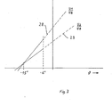
- FIG. Three shows a diagram for dimensioning the amplifiers according to FIG. 2
- FIG. Four shows a diagram
- FIG. 5 shows a circuit for a heat pump
- FIG. 6 shows a circuit for a circulating water heater.
- the diagram according to FIG. 1 shows the dependency of the pulse pause ratio P / T as a function of the outside temperature ⁇ in degrees Celsius.
- the zero point of the diagram is assumed with a pulse pause ratio P / T o equal to zero and an outside temperature of minus twenty degrees Celsius.
- a compression heat pump is assumed for the exemplary embodiment, although the control system is equally good for a down sorption or resorption heat pump is applicable. It is also irrelevant whether the heat pump is a heating heat pump or a cooling heat pump. From the diagram two curve parts 1 and 2 can be seen, which touch at a point 3.
- Curve 1 assumes a P / T ratio of zero, which is set at an outside temperature of minus 15 degrees Celsius. It is assumed here that a heat pump below a temperature of minus 15 degrees Celsius is no longer able to extract any appreciable output; here, only a boiler or other heat source must be used for heating.
- curve 1 In the range from minus 15 degrees to the abscissa value of point 3, that is minus 6 degrees, it has been found that curve 1 would be the optimal curve according to which heating would be carried out by means of the heat pump and with the connection of any heat source. The task now is to find a function that comes closest to this optimal curve 1.
- P means the opening time in seconds
- T o the period in seconds
- P o a dimensionless constant
- ⁇ the outside temperature in degrees Celsius
- 1 and ⁇ 2 two selected constants with the dimension degrees Celsius.
- T o For periodic opening and closing, a period T o is first defined.
- the value is expediently chosen for a specific heat pump between a minimum value which should not be undercut due to the frequent switching of the expansion valve and a maximum value which still ensures an approximately continuous evaporation process in the evaporator.
- the specific choice of the exact size of the constant can only depend on the well-known heat pump. in the exemplary embodiment, a period P o of sixty seconds is selected.
- ⁇ 1 is chosen to be minus 15 degrees Celsius in the exemplary embodiment. You could set ⁇ 1 so that it corresponds to the design temperature of a heating system. The type and choice of ⁇ 1 defines the point below which there is no heat delivery as the value of the outside temperature. When the numerator of the fraction ⁇ minus ⁇ 1 becomes zero, the pulse-pause ratio becomes zero, so that the expansion valve remains closed.
- the value for ⁇ 2 is preferably chosen to be minus 20 degrees Celsius in the exemplary embodiment. For the general choice of the values of ⁇ 2 and T o , the course of the pulse-pause ratio approximates the setpoint curve 1 as precisely as possible.
- ⁇ 2 depends only on the position curvature of the curve, while the constant P o is to be determined in such a way that the value of the pulse-pause ratio required in point three in FIG. This value is referred to as P s below.
- ⁇ 1 becomes the description of the function according to curve 2 18 degrees Celsius is selected, which is the value above which heating power is no longer necessary.
- ⁇ 2 is chosen to be 33 degrees Celsius.
- the curve of the pulse-pause ratio P / T from the minimum outside temperature up to which the heat output of the heat pump should still take place, up to the maximum outside temperature above which the heat output of the heat pump should no longer take place, can be defined.
- the maximum of the pulse-pause ratio is recognizable at the point at which heating of the heating system by the heat pump is just still possible.
- FIG. 2 shows the circuit with which the control according to equation 1 is carried out.
- the circuit according to FIG. 2 has an outside temperature sensor 4, which consists of a temperature-dependent resistor, for example an NTC resistor.
- the resistor is connected via a line 5 to a transducer 6, which is connected to an output 7 gives a voltage that obeys the condition according to equation two.
- This transducer emits a signal that varies almost proportionally with the outside temperature.
- U mean a the output voltage on line 7 in volts
- U b a reference voltage
- ⁇ the current outside temperature in degrees Celsius
- ⁇ a and ⁇ b the temperature values in degrees Celsius.
- ⁇ a and ⁇ b compare figure four.
- Four shows a diagram which shows a voltage curve 8 which shows the voltage ratio U a / U b as a function of the outside temperature ⁇ .
- ⁇ a means a temperature at which the measured value converter 6 supplies a voltage 0 at its output corresponding to a U a / U b equal to zero.
- ⁇ b a voltage ratio U a / U b equal to one is reached.
- the straight line between them thus runs between points 9 and 10.
- the values of ⁇ a and ⁇ b are chosen such that in the area between ⁇ a and ⁇ b the entire curve according to FIG.
- the output of the measured value converter 6 is shown at a branch point 11 in two lines 12 and 13, which are fed to the inputs of two amplifiers 14 and 15.
- the amplifiers 14 and 15 are semiconductor proportional amplifiers which must obey the following conditions. It applies to amplifier 14 that it fulfills the function according to equation 3.
- U 1 is the output voltage in volts
- U b the reference voltage in volts
- a 1 and b 1 dimensionless coefficients The choice of the coefficients a 1 and b 1 is dependent on ⁇ 1 and ⁇ 2, which will be discussed later.
- the amplifier 15 obeys the dependence according to equation 4, where what has just been said applies analogously to a 2 and b 2 .
- the outputs of the two amplifiers 14 and 15 are connected on lines 16 and 17, the line 16 directly forming the one input of the comparator 18, while the line 17 is connected to an integrator 19, the output 20 of which is connected via a line 21 to the inverting one Input of the comparator 18 is connected.
- a square-wave voltage signal with the period T is present on a line 22.
- the line 22 is connected to the integrator 19 via a line 23, it is also connected to an input of an AND gate 24, the other input 25 of which forms the output of the comparator 18.
- An output 26 of the AND gate leads to a solenoid 27, which is the drive coil of the expansion valve.
- the diagram according to FIG. 3 is now used for the design and dimensioning of the amplifiers.
- the outside temperature ⁇ is plotted in degrees Celsius on the abscissa and the ratio of the voltage U 1 or U 2 to U b is plotted on the ordinate.
- the amplifier 14 obeys the curve 28, the Ver stronger 15 of curve 29. Both curves are straight lines and are defined by the fact that their point of intersection lies at 9 1, ie at minus 15 degrees Celsius.
- the slopes of the curves are selected such that in the control's working range, that is to say in the case of curve 1 in FIG. 1, from minus 15 to minus 6 degrees Celsius, the voltage U 1 is greater than the voltage U 2 .
- the integrator 19 is constructed in principle in accordance with FIG.
- the integrator 19 has a voltage current converter 30 arranged in the course of the line 17 of the figure, the output of which is connected to the line 21.
- the line 21 is connected via a line 31, in which a resistor 32 with a capacitor 33 is connected in series, to the point 34 of the reference voltage source U b .
- a line 35 branches off between the capacitor and the resistor and is likewise connected to the reference voltage source 34 via a clock contact 36.
- the clock contact 36 is actuated by a relay coil 37, which is connected to the line 22 lying voltage source is connected. This means that whenever a pulse is present in accordance with the period T o, the relay 37 is supplied with voltage and its contact 36 opens.
- the voltage signal of line 16 corresponds to signal U 1
- the voltage signal of line 17 corresponds to voltage signal U 2
- the voltage U 2 is thus present via the line 21 at the inverted input of the comparator 18. Since this voltage is less than the voltage U 1 , the comparator 18 is switched through, that is to say that a signal is present at the AND gate 24 via the line 25, but this is not yet the absence of a signal on the line 22 to the excitation coil of the expansion valve is passed on.
- a rectangular voltage signal with period t is present on line 22. This means that at the beginning of a period, a positive voltage signal is given via line 23 to the integrator, which is present at the other input of the AND element 24 at the same time. This means that at the beginning of the period with the period T, the AND gate 24 switches through and the expansion valve opens.
- the voltage signal compare the structure of the integrator 19 according to FIG. 5, causes the contact 36 to open.
- the capacitor 33 can thus be charged via the resistor 32 from the output of the constant current source 30.
- the constant current only depends on the height in its absolute value the outside temperature.
- the capacitor charging voltage thus rises over time until it is equal to the value of U 1 .
- the comparator then switches off.
- One input of the AND element is de-energized, so that the excitation coil of the expansion valve is de-energized, the duty cycle during the period To is ended.
- the ratio of the ordinate difference between curves 28 and 29 at each abscissa point to the ordinate value of curve 29 is not constant.
- the control of the heat pump follows curve 2 in FIG. 1, it must be taken into account that here the voltages Ui / U b and U 2 / U b run with a slope that is negative to the slope in FIG.
- the same consideration remains with regard to the ordinates and ordinate difference values.
- Burner 46 and heat exchanger 42 are arranged within a combustion chamber 50, which has an exhaust gas outlet 51 at the top, in which an exhaust gas fan 52 is arranged.
- the exhaust gas fan is controlled by a fan motor 53 which drives the fan via a shaft 54 to which a speed sensor 55 is connected, which is connected to a control sensor 57 via an electrical measured value transmission line 56.
- the control transmitter 57 acts on the fan motor 53 via an actuating line 58.
- An exhaust gas probe 59 in the form of an oxygen or carbon dioxide sensor is connected downstream of the exhaust gas fan and is connected via a measuring line 60 to a controller 61, the output signal of which is connected via a line 62 to the control transmitter 57 is switched.
- An outside temperature sensor 63 is provided, which could also be represented by a manually operated potentiometer, but which is in any case connected to a flow temperature controller 65 via a line 64 as a setpoint generator.
- the signal from the flow temperature sensor 44 is also present at this flow temperature controller as an actual value encoder via a line 66.
- the output of the controller 65 is connected via a line 67 to the control 68 incorporating the invention.
- the line 67 is also connected to the actuator 49 of the proportional solenoid valve 47.
- the control 68 is also connected via an RC element 69 in the course of a line 70 to an input of the control transmitter 57.
- the output signal of the flow temperature controller 65 acts on the controller 68, so that the gas throughput is adjusted once there is a control deviation of the flow temperature and the fan speed is readjusted. The same also happens if the controller is defective and an actually inappropriate output signal is issued by the controller.
- the object of the invention is to convert the analog value on line 67 into a corresponding fan speed. For this purpose it is of course necessary to provide an association between the speed of the fan and its delivery volume within the framework of the control 68. Furthermore, it must of course be taken into account in the context of the controller 68 that there is a certain relationship between the analog signal at the output of the controller 65 and the actual gas throughput in the line 48.
- the ratio P: T corresponds to the relative duty cycle within a period
- P is a dimensionless constant
- T is the period in seconds
- ⁇ is the output voltage at the output of the regulator 65.
- point 11 in the exemplary embodiment according to Figure two corresponds to the voltage level on line 67 at the output of regulator 65.
- the values ⁇ 1 and ⁇ 2 are selected constants with the dimension volt. ⁇ then also has the dimension volt.
- the information relating to the exemplary embodiment with regard to the frequency of the pulse-pause ratio, which applied to the heat pump, is not necessarily applicable to the relationships to the exemplary embodiment according to FIG.
- the frequency is to be chosen considerably higher.
Landscapes
- Engineering & Computer Science (AREA)
- Physics & Mathematics (AREA)
- Mechanical Engineering (AREA)
- Thermal Sciences (AREA)
- General Engineering & Computer Science (AREA)
- General Physics & Mathematics (AREA)
- Automation & Control Theory (AREA)
- Control Of Temperature (AREA)
- Compression-Type Refrigeration Machines With Reversible Cycles (AREA)
- Control Of Eletrric Generators (AREA)
Priority Applications (1)
| Application Number | Priority Date | Filing Date | Title |
|---|---|---|---|
| AT84730025T ATE72065T1 (de) | 1983-03-22 | 1984-03-20 | Verfahren zum steuern einer elektrischen ausgangsgroesse mittels eines pulspausenverhaeltnisses. |
Applications Claiming Priority (2)
| Application Number | Priority Date | Filing Date | Title |
|---|---|---|---|
| DE8308855 | 1983-03-22 | ||
| DE8308855U | 1983-03-22 |
Publications (3)
| Publication Number | Publication Date |
|---|---|
| EP0123643A2 true EP0123643A2 (fr) | 1984-10-31 |
| EP0123643A3 EP0123643A3 (en) | 1986-01-22 |
| EP0123643B1 EP0123643B1 (fr) | 1992-01-22 |
Family
ID=6751589
Family Applications (1)
| Application Number | Title | Priority Date | Filing Date |
|---|---|---|---|
| EP84730025A Expired - Lifetime EP0123643B1 (fr) | 1983-03-22 | 1984-03-20 | Procédé de commande d'une grandeur de sortie au moyen d'un rapport cyclique |
Country Status (3)
| Country | Link |
|---|---|
| EP (1) | EP0123643B1 (fr) |
| AT (1) | ATE72065T1 (fr) |
| DE (1) | DE3485468D1 (fr) |
Cited By (3)
| Publication number | Priority date | Publication date | Assignee | Title |
|---|---|---|---|---|
| DE3832226A1 (de) * | 1988-09-22 | 1990-04-12 | Danfoss As | Kaelteanlage und verfahren zur steuerung einer kaelteanlage |
| GB2231688A (en) * | 1989-05-10 | 1990-11-21 | Mitsubishi Electric Corp | Air conditioner |
| EP0378152A3 (fr) * | 1989-01-11 | 1991-02-20 | KÜBA KÄLTETECHNIK GmbH | Procédé pour optimaliser la performance d'évaporateurs de réfrigérant |
Family Cites Families (4)
| Publication number | Priority date | Publication date | Assignee | Title |
|---|---|---|---|---|
| FR2305054A1 (fr) * | 1975-03-18 | 1976-10-15 | Saunier Duval | Dispositif d'asservissement de la commande du moteur de ventilateur d'extraction pour chaudiere a gaz a tirage force |
| DE2644919C2 (de) * | 1976-10-05 | 1983-05-11 | Gebrüder Haake GmbH, 7500 Karlsruhe | Vorrichtung zur Regelung der Temperatur eines Wärmeübertragers |
| FR2423811A1 (fr) * | 1978-04-19 | 1979-11-16 | Ferodo Sa | Procede et installation de regulation de la temperature d'une enceinte chauffee par de l'air, notamment d'un habitacle de vehicule automobile |
| DE3328190A1 (de) * | 1982-08-28 | 1984-03-01 | Joh. Vaillant Gmbh U. Co, 5630 Remscheid | Verfahren zur bildung eines sollwertes einer regel- beziehungsweise steuereinrichtung fuer eine heizungsanlage |
-
1984
- 1984-03-20 DE DE8484730025T patent/DE3485468D1/de not_active Expired - Lifetime
- 1984-03-20 EP EP84730025A patent/EP0123643B1/fr not_active Expired - Lifetime
- 1984-03-20 AT AT84730025T patent/ATE72065T1/de not_active IP Right Cessation
Cited By (7)
| Publication number | Priority date | Publication date | Assignee | Title |
|---|---|---|---|---|
| DE3832226A1 (de) * | 1988-09-22 | 1990-04-12 | Danfoss As | Kaelteanlage und verfahren zur steuerung einer kaelteanlage |
| GB2225873A (en) * | 1988-09-22 | 1990-06-13 | Danfoss As | Refrigeration apparatus and methods of controlling a refrigeration apparatus |
| GB2225873B (en) * | 1988-09-22 | 1992-11-25 | Danfoss As | Refrigeration apparatus and methods of controlling a refrigeration apparatus |
| EP0378152A3 (fr) * | 1989-01-11 | 1991-02-20 | KÜBA KÄLTETECHNIK GmbH | Procédé pour optimaliser la performance d'évaporateurs de réfrigérant |
| GB2231688A (en) * | 1989-05-10 | 1990-11-21 | Mitsubishi Electric Corp | Air conditioner |
| US5039008A (en) * | 1989-05-10 | 1991-08-13 | Mitsubishi Denki Kabushiki Kaisha | Air conditioner |
| GB2231688B (en) * | 1989-05-10 | 1993-06-16 | Mitsubishi Electric Corp | Air conditioner |
Also Published As
| Publication number | Publication date |
|---|---|
| EP0123643B1 (fr) | 1992-01-22 |
| ATE72065T1 (de) | 1992-02-15 |
| DE3485468D1 (de) | 1992-03-05 |
| EP0123643A3 (en) | 1986-01-22 |
Similar Documents
| Publication | Publication Date | Title |
|---|---|---|
| DE2954078C2 (fr) | ||
| DE3424088C2 (fr) | ||
| CH641905A5 (de) | Druckregeleinrichtung fuer pneumatische druecke, insbesondere in fahrzeugen. | |
| DE3638410C2 (fr) | ||
| EP1154202A2 (fr) | Dispositif de commmande pour un brûleur | |
| DE2531015C2 (de) | Einrichtung zur Regulierung der Beheizung eines Kraftfahrzeuges | |
| DE3036291A1 (de) | Heizanlage | |
| DE3237816A1 (de) | Verfahren und vorrichtung zur regelung der luftdurchsatzmenge in einer klimaanlage | |
| DE3425445C2 (fr) | ||
| EP0014369B1 (fr) | Régulateur de pression pour freins pneumatiques de véhicules, notamment de véhicules sur rails | |
| EP0123643B1 (fr) | Procédé de commande d'une grandeur de sortie au moyen d'un rapport cyclique | |
| EP0615095B1 (fr) | Commande de brûleur | |
| DE4005255C2 (de) | Schaltungsanordnung zum Betrieb eines Stellgliedes | |
| DE3410764A1 (de) | Verfahren zum steuern einer elektrischen ausgangsgroesse mittels eines pulspausenverhaeltnisses | |
| EP1235131A2 (fr) | Régulation de la température d'une pièce | |
| DE2732916C3 (de) | Temperaturabhängiger elektronischer Regelschalter | |
| DE3442441A1 (de) | Verfahren zum ermitteln der fuer eine schnellaufheizung eines raumes benoetigten zeit | |
| DE2910294A1 (de) | Temperaturregler | |
| EP0614051B1 (fr) | Automate à brûleur | |
| EP1243818B1 (fr) | Dispositif de commande électrique pour mécanisme de transmission d'un véhicule automobile | |
| DE3328190C2 (fr) | ||
| EP0107774B1 (fr) | Dispositif de régulation pour une installation de chauffage | |
| DE19503630C2 (de) | Verfahren zum kondensatfreien Betreiben eines Umlaufwasserheizers | |
| DE2834025A1 (de) | Gasbeheiztes geraet, insbesondere wassererhitzer | |
| DE2644919C2 (de) | Vorrichtung zur Regelung der Temperatur eines Wärmeübertragers |
Legal Events
| Date | Code | Title | Description |
|---|---|---|---|
| PUAI | Public reference made under article 153(3) epc to a published international application that has entered the european phase |
Free format text: ORIGINAL CODE: 0009012 |
|
| AK | Designated contracting states |
Designated state(s): AT BE CH DE FR GB IT LI LU NL SE |
|
| PUAL | Search report despatched |
Free format text: ORIGINAL CODE: 0009013 |
|
| AK | Designated contracting states |
Designated state(s): AT BE CH DE FR GB IT LI LU NL SE |
|
| 17P | Request for examination filed |
Effective date: 19860702 |
|
| 17Q | First examination report despatched |
Effective date: 19880624 |
|
| RAP1 | Party data changed (applicant data changed or rights of an application transferred) |
Owner name: VAILLANT GMBH Owner name: VAILLANT-SCHONEWELLE B.V. Owner name: VAILLANT LTD. Owner name: VAILLANT GES.M.B.H Owner name: VAILLANT S.A.R.L Owner name: N.V. VAILLANT S.A. Owner name: JOH. VAILLANT GMBH U. CO. |
|
| GRAA | (expected) grant |
Free format text: ORIGINAL CODE: 0009210 |
|
| AK | Designated contracting states |
Kind code of ref document: B1 Designated state(s): AT BE CH DE FR GB IT LI LU NL SE |
|
| PG25 | Lapsed in a contracting state [announced via postgrant information from national office to epo] |
Ref country code: FR Effective date: 19920122 |
|
| REF | Corresponds to: |
Ref document number: 72065 Country of ref document: AT Date of ref document: 19920215 Kind code of ref document: T |
|
| PGFP | Annual fee paid to national office [announced via postgrant information from national office to epo] |
Ref country code: SE Payment date: 19920217 Year of fee payment: 9 |
|
| PGFP | Annual fee paid to national office [announced via postgrant information from national office to epo] |
Ref country code: LU Payment date: 19920221 Year of fee payment: 9 |
|
| REF | Corresponds to: |
Ref document number: 3485468 Country of ref document: DE Date of ref document: 19920305 |
|
| PGFP | Annual fee paid to national office [announced via postgrant information from national office to epo] |
Ref country code: FR Payment date: 19920316 Year of fee payment: 9 |
|
| ITF | It: translation for a ep patent filed | ||
| GBT | Gb: translation of ep patent filed (gb section 77(6)(a)/1977) | ||
| EN | Fr: translation not filed | ||
| EPTA | Lu: last paid annual fee | ||
| PLBE | No opposition filed within time limit |
Free format text: ORIGINAL CODE: 0009261 |
|
| STAA | Information on the status of an ep patent application or granted ep patent |
Free format text: STATUS: NO OPPOSITION FILED WITHIN TIME LIMIT |
|
| PGFP | Annual fee paid to national office [announced via postgrant information from national office to epo] |
Ref country code: GB Payment date: 19921220 Year of fee payment: 10 |
|
| 26N | No opposition filed | ||
| PGFP | Annual fee paid to national office [announced via postgrant information from national office to epo] |
Ref country code: BE Payment date: 19930208 Year of fee payment: 10 |
|
| PG25 | Lapsed in a contracting state [announced via postgrant information from national office to epo] |
Ref country code: LU Free format text: LAPSE BECAUSE OF NON-PAYMENT OF DUE FEES Effective date: 19930320 |
|
| PG25 | Lapsed in a contracting state [announced via postgrant information from national office to epo] |
Ref country code: SE Effective date: 19930321 |
|
| REG | Reference to a national code |
Ref country code: FR Ref legal event code: AR |
|
| REG | Reference to a national code |
Ref country code: FR Ref legal event code: DI |
|
| NLT1 | Nl: modifications of names registered in virtue of documents presented to the patent office pursuant to art. 16 a, paragraph 1 |
Owner name: VAILLANT B.V. TE AMSTERDAM. |
|
| PG25 | Lapsed in a contracting state [announced via postgrant information from national office to epo] |
Ref country code: GB Effective date: 19940320 |
|
| PG25 | Lapsed in a contracting state [announced via postgrant information from national office to epo] |
Ref country code: BE Effective date: 19940331 |
|
| BERE | Be: lapsed |
Owner name: S.A. VAILLANT N.V. Effective date: 19940331 |
|
| GBPC | Gb: european patent ceased through non-payment of renewal fee |
Effective date: 19940320 |
|
| EUG | Se: european patent has lapsed |
Ref document number: 84730025.8 Effective date: 19931008 |
|
| PGFP | Annual fee paid to national office [announced via postgrant information from national office to epo] |
Ref country code: NL Payment date: 19951218 Year of fee payment: 13 |
|
| PGFP | Annual fee paid to national office [announced via postgrant information from national office to epo] |
Ref country code: AT Payment date: 19960229 Year of fee payment: 13 |
|
| PGFP | Annual fee paid to national office [announced via postgrant information from national office to epo] |
Ref country code: DE Payment date: 19960322 Year of fee payment: 13 |
|
| PGFP | Annual fee paid to national office [announced via postgrant information from national office to epo] |
Ref country code: CH Payment date: 19960328 Year of fee payment: 13 |
|
| PG25 | Lapsed in a contracting state [announced via postgrant information from national office to epo] |
Ref country code: AT Effective date: 19970320 |
|
| PG25 | Lapsed in a contracting state [announced via postgrant information from national office to epo] |
Ref country code: LI Effective date: 19970331 Ref country code: CH Effective date: 19970331 |
|
| PG25 | Lapsed in a contracting state [announced via postgrant information from national office to epo] |
Ref country code: NL Effective date: 19971001 |
|
| REG | Reference to a national code |
Ref country code: CH Ref legal event code: PL |
|
| NLV4 | Nl: lapsed or anulled due to non-payment of the annual fee |
Effective date: 19971001 |
|
| PG25 | Lapsed in a contracting state [announced via postgrant information from national office to epo] |
Ref country code: DE Effective date: 19971202 |