EP0123665A2 - Verfahren um in einem Steuersystem die Antwortgenauigkeit zu verändern - Google Patents
Verfahren um in einem Steuersystem die Antwortgenauigkeit zu verändern Download PDFInfo
- Publication number
- EP0123665A2 EP0123665A2 EP84850127A EP84850127A EP0123665A2 EP 0123665 A2 EP0123665 A2 EP 0123665A2 EP 84850127 A EP84850127 A EP 84850127A EP 84850127 A EP84850127 A EP 84850127A EP 0123665 A2 EP0123665 A2 EP 0123665A2
- Authority
- EP
- European Patent Office
- Prior art keywords
- magnitude
- displacement
- unit
- output
- input
- Prior art date
- Legal status (The legal status is an assumption and is not a legal conclusion. Google has not performed a legal analysis and makes no representation as to the accuracy of the status listed.)
- Granted
Links
Images



Classifications
-
- B—PERFORMING OPERATIONS; TRANSPORTING
- B64—AIRCRAFT; AVIATION; COSMONAUTICS
- B64C—AEROPLANES; HELICOPTERS
- B64C13/00—Control systems or transmitting systems for actuating flying-control surfaces, lift-increasing flaps, air brakes, or spoilers
- B64C13/24—Transmitting means
- B64C13/38—Transmitting means with power amplification
- B64C13/50—Transmitting means with power amplification using electrical energy
Definitions
- This invention relates to control systems that have a variable gain or ratio between displacement of a manipulatable control unit and a controlled device that is actuated in response to the control unit; and the invention is more particularly concerned with a method of varying the gain in such a system so that it operates with a low gain for small displacements of the control unit in conditions and positions of its displacement wherein fine response of the controlled device is desirable but operates with high gain in conditions and positions of control unit displacement wherein a coarse or rapid response of the controlled device is desirable.
- the system for pitch control of a high performance aircraft can be taken as typical of the various types of control systems that involve the problems and requirements addressed by this invention.
- the elevators or other pitch control surface are preferably actuated through large changes of position, in order to produce quick and positive responses to such control unit displacements.
- the control system should appropriately have a relatively high gain.
- a high-gain control system does not lend itself well to precise control, and particularly to fine trimming adjustments.
- the relatively large control surface actuation produced by a small displacement of the control unit is likely to result in an overcorrection, to which the pilot reacts with a correction in the opposite direction that may also turn out to be excessive.
- Such pilot induced oscillations further complicate the difficulty of achieving precise control with a high-gain system.
- the pitch control system Around the neutral or null point of the pitch control system, where the trimming of aircraft attitude is of greatest importance, it is appropriate and desirable for the system to have a low gain. If a large and rapid change of pitch attitude is desired, the stick will normally be displaced rapidly away from its neutral position through a range of positions in which a high gain is desirable. However, even at relatively large deflections of the pitch-controlling actuated surface, precise trimming of that surface may be necessary, as for gun aiming in a diving or steeply climbing fighter aircraft.
- it is an object of this invention to provide a method of controlling response fineness in a control system comprising a manipulatable unit that is displaceable toward and from a null position and a controlled device that is actuated toward and from a neutral position in response to displacements of said unit, said method providing for automatic selection as between high gain and low gain when the control unit is in a range of its positions that begins at a predetermined distance from its null position and extends away from that position, to cause the system to operate with high gain when the control unit is manipulated through large dis- plaments in said range but to operate with low gain when the control unit is manipulated through any small displacement in said range that directly follows a reversal of the direction of its displacement and thus characterizes a trimming operation.
- a control system to which the method of this invention is applicable comprises a manipulatable control unit 1, which is here illustrated as an aircraft control stick intended to be manually manipulated but which could be subjected to mechanical actuation, as by means of an automatic pilot.
- the control unit is supported for swinging displacement about an axis X-X, but it could as well be displaceable in translation.
- the control unit 1 will in any case have a neutral or null position towards and from which it is displaceable; and. it may be displaceable away from the null position in only one direction or, as in the case of an aircraft stick in both directions.
- a signal transmitter 2 Connected to the control unit 1 is a signal transmitter 2 that generates an input which can be in analog form,.as a steady signal of varying magnitude, or can be in digital form.
- Digital input signals are generated at regular intervals, typically at a frequency of 50 Hz.
- the input has a magnitude ⁇ IN which at each instant unambiguously corresponds to the existing position of displacement of the control unit 1.
- the magnitude S IN can be considered to be the same thing as the input itself.
- each can be considered as identifying a position of the control unit, and the instantaneous magnitude of an analog input likewise signifies the concurrent position of that unit. It is here assumed that the input 6IN is positive for control unit positions at one side of the null position and negative for those at the opposite side of the null position.
- the input from the transmitter 2 is fed to a computing unit 3 by which an actuating output TOUT is produced that may be in digital or analog form.
- the computing unit 3 is connected with an amplifier 4 from which the actuating output, as amplified, is in turn fed to an actuating instrumentality 6 in the form of a servo unit.
- the servo unit 6 is mechanically linked to a control surface 5 which the control unit actuates in response to the amplified actuating output, to bring it to a position of displacement e that is dependent upon the position of displacement ⁇ IN of the control unit 1 and upon other factors that are explained hereinafter.
- the servo unit 6 and the control surface 5 that it actuates thus comprise a controlled device.
- the computing unit 3 is preferably a data processor that is programmed for the algorithms needed for various control situations.
- the computing unit can comprise discrete components for working through the algorithms digitally or in analog form.
- the data processor comprises, in general, a central unit 31, a program memory 32 and a primary memory 33- Interfaces 34 and 35, respectively connected to the input and to the output of the data processor, match the input ⁇ IN to the data processor and the output ⁇ OUT to the amplifier 4 and the servo unit 6.
- the data processor 3 is programmed to work through an algorithm, explained hereinafter, whereby, it determines, for each generated input ⁇ IN , a magnitude ⁇ OUT that corresponds to an angle 6 to which the controlled device is to be actuated in response to that input signal. That algorithm is stored in the program memory 32, and the box 7 in FIG. 1 designates a known type of instrumentality by which it is worked through.
- the output magnitude ⁇ OUT may be modified by further processing, as denoted by the boxes 8 and 9 in FIG. 1, to adjust it for flight conditions, load factor and the like, and thus convert it to the actuating output ⁇ OUT , which represents a demand value that unambiguously designates the angle e to which the controlled device is to be actuated.
- the modifications made in the calculated ⁇ 0UT magnitude to obtain the ⁇ OUT actuating output signal will be disregarded, and it will be assumed (as can be the case) that the actuating output has the ⁇ OUT magnitude. Accordingly, the magnitude ⁇ OUT is sometimes herein designated as the output.
- FIG. 2 represents, for positive displacements of the control stick, the relationships between input 6IN and output ⁇ OUT .
- control unit movement away from the null position is herein designated the "increase” direction, since such movement effects an increased deflection of the controlled device, and the opposite direction of control unit displacement is designated the “decrease” direction.
- a first range of positions of displacement of the stick or control unit extending from the null or neutral point 0 to a position designated by ⁇ E , the system operates with a low gain, that is, a given increment of stick displacement brings about a relatively small increment of controlled device displacement, as denoted by the line segment OE, which represents a sequence of relationships between input signals 6IN and output signals ⁇ OUT .
- this low gain operation attends movements of the stick in both directions and thus facilitates accurate trimming in attitudes of substantially level flight.
- the point ⁇ H may be at the limit of displacement of the stick in the increase direction, or there may be a range of positions of the stick between its ⁇ H position and its limit position; and in the latter case the gain in that range, for both directions of control unit movement, may be different from the gain in the high gain range ⁇ F - ⁇ H , and may be the same as, or different from, the gain in the initial range O- ⁇ E.
- the line segment GE lies to the left of the above discussed line segment FH, and its slope or gradient y 2 is equal to --or at least generally similar to-- the slope or gradient y 1 of the segment FH, so that the line segments GE and FH are more or less parallel to one another.
- the respective increments of controlled device displacement ⁇ that are depicted by the respective lines FH and GE will be equal --or substantially so-- and relatively high; but for a given position of displacement of the stick, the corresponding point on the segment GE designates a greater angle of displacement ⁇ of the controlled device than the corresponding point on the segment FH.
- T 1 designates a turning point at which the direction of stick displacement has been reversed from increase to decrease
- T 2 designates a turning point at which the direction of stick displacement has been reversed from decrease to increase.
- the slope or gradient ⁇ 3 of the line segment y 3 is on the order of the slope ⁇ 4 of the line segments OE and EF, which is to say that it represents a relatively low gain, whereby a given increment of control stick displacement is attended by a relatively small displacement of the controlled device.
- the line y 3 in FIG. 2 is one of a set of lines which can be visualized as drawn across the segments EH and GE to represent relationships of input to output signals after each of various turning points, each line of that set having a slope or gradient equal to --or substantially equal to-- that of the illustrated line y 3 .
- the line segment EF is in effect a member of this set, as is the line segment GH.
- the several line segments EF, FH, HG and GE can be regarded as defining a belt-like modulation zone EFHGE wherein output signals ⁇ OUT are dependent not only upon their related input signals ⁇ IN but also upon the manner in which the stick had been manipulated immediately before each output signal was produced.
- output signals ⁇ OUT are dependent not only upon their related input signals ⁇ IN but also upon the manner in which the stick had been manipulated immediately before each output signal was produced.
- incremental stick displacements in the range of displacement positions between ⁇ E and ⁇ H can result in relatively large (high gain) incremental displacements of the controlled device or relatively small (low gain) displacements of that device.
- the output signal produced in response to every input signal in the range between ⁇ E and 6 H can be visualized as lying in the modulation zone EFHGE or on one of the segments that bound it.
- each of the several line segments OE, EF, FH, GE and Y3 may be either rectilinear or curvilinear, that is, it may have either a constant slope or gradient or one'that increases in a non-uniform manner. Also, since the segments FH and GE need not be exactly parallel, the modulation zone EFHGE may be either wider or narrower at its top than at its bottom.
- FIG. 3 is a diagram for an aircraft pitch control system having rectilinear sequences of input signal to output signal relationships and having a modulation zone E'F'H'G'E' corresponding to the modulation zone for stick-back positions shown in FIG. 2 and a second generally similar zone ABDCA for forward stick positions.
- the stick-forward zone ABDCA is limited to a smaller range of stick positions than the stick-back zone E'F'H'G'E'.
- the diagram is in other respects the same for both sides of the neutral point O.
- the line segment OE' in FIG. 3 represents a first sequence of relationships between input signal magnitudes and output signal magnitudes that is defined and stored in the memory of the system.
- the sequence may be in the form of discrete values, or it can have the form of a function that defines a continuum of values.
- the output magnitudes ⁇ OUT in this first sequence are related to respective input signals b IN that designate positions of the control unit 1 between its null position and a position ⁇ E that is spaced from the null position by a predetermined distance in the increase direction.
- the output signal magnitudes ⁇ OUT in this first sequence have a gradient k 3 of increase in the increase direction relative to their related input signal magnitudes, which gradient, as explained above, corresponds to a relatively low gain.
- the line segment G'E' represents a second sequence of relationships between input and output signal magnitudes, likewise stored in the system memory either as discrete values or as a function.
- the output signals of this second sequence are related to respective input signals 6IN that designate positions of the control unit 1 between its ⁇ E position and a predetermined position ⁇ G that is spaced a substantial distance beyond ⁇ E in the increase direction.
- the output signal magnitudes in this second sequence have a second gradient k l of increase in the increase direction, said second gradient being substantially higher --that is, steeper-- than the gradient k 3 .
- the line segment F'H' represents a third sequence of relationships between input and output signal magnitudes, likewise stored in the system memory either as discrete values or as a function.
- the output signals ⁇ OUT of this third sequence are related to respective input signals ⁇ IN that designate positions of the control unit 1 between a position ⁇ F that is intermediate its ⁇ E and ⁇ G positions and a position ⁇ H that is spaced beyond the ⁇ G position in the increase direction.
- the gradient of this third sequence is in this case equal to the gradient k l of the second sequence.
- the related output signal magnitude ⁇ OUT in the third sequence F'H' signifies a smaller displacement of the controlled unit 6, 5 from its neutral position than the related output signal magnitude in the second sequence G'E'.
- the line Y3 represents one of a set of "trim” sequences of relationships between input and output signal magnitudes, similarly defined and stored in the system memory.
- the output signal magnitudes in each "trim” sequence are related to respective input signals ⁇ IN that designate positions of the control unit 1 between its ⁇ E position and its ⁇ H position. All of the "trim” sequences have like gradients or slopes that are in this case equal to the gradient k 3 of the first sequence.
- each "trim” sequence includes an output signal magnitude that is in the second sequence (G'E') and a different output signal magnitude that is in the third sequence (F'H'); and these two output signal magnitudes, which can be considered identifier magnitudes, can be visualized as the points at which the "trim" sequence line Y3 (or any "trim” sequence line parallel to it) intersects the respective line segments G'E' and F'H'.
- sequences of input signal to output signal relationships that are generally similar to those described above for the stick-back positions are also defined and stored for the stick-forward range.
- information is temporarily stored that relates to the magnitude of each generated input signal and the magnitude of the output signal that was produced in response to it. Such information is employed in determining the magnitude of the output signal that is to be produced in response to the next generated input signal. After that next output signal is produced, the stored information can be discarded.
- the stored ⁇ IN / ⁇ OUT information designates a point which can be visualized as located between the line segments G'E' and F ' H ', then the stored information likewise designates a particular one of the "trim” sequences, since the ⁇ IN / ⁇ Out relationships in each "trim” sequence (other than those for the identifier 6 0UT magnitudes) are all unique to that particular sequence.
- the method proceeds on an initial assumption that the output signal to be produced in response to a newly generated input signal is to have the magnitude which is related to that input signal in the "trim" sequence identified by the stored information for the last preceding input signal.
- the method assumes that the stored information about the last preceding ⁇ IN / ⁇ OUT signal pair designates a turning point, and the analysis continues on the assumption that the output signal magnitude for the newly generated input signal is to be determined from the particular "trim" sequence identified by the stored information.
- each "trim" sequence extends substantially to the left and to the right of the modulation area EFHGE, and therefore the presumptive output signal magnitude may fall within that area or may fall outside of it, either to the left of it or to the right of it. If the presumptive output signal magnitude falls within the area E'F'H'G'E', that is, if it is neither larger than the magnitude designated by T 1 nor smaller than the magnitude designated by T 2 , then the presumptive output signal magnitude is adopted as the actual output signal magnitude to be produced in response to the newly generated input signal.
- the point P in FIG. 3 illustrates a case in which the presumptive output signal magnitude falls outside the modulation zone E'P'H'G'E' .
- T l is the point designated by the stored information
- the fact that the point P is outside (to the right of) the modulation zone means that T 1 was not in fact a turning point, the stick has continued its movement in the increase direction, and the correct new output signal would be the one in the sequence F'H' that is related to the newly generated input signal.
- a presumptive output signal magnitude to the left of the sequence G'E' would signify a continued movement of the stick in the decrease direction, and the actual output signal magnitude would be the one in the G'E' sequence that is related to the newly generated input signal.
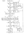
- the newly generated input signal ⁇ IN is compared with the input signal magnitude 6 INA for the forward limit of the stick-forward modulation zone ABDCA, to determine whether the newly generated ⁇ IN signal has a magnitude less than that compared ⁇ INA magnitude. If it has --signifying that the stick is at or forward of the ⁇ A position-- the output signal that is produced has the magnitude ⁇ OUTA , which is assigned to the ⁇ INA input signal magnitude, as illustrated by the box 24.
- This output signal magnitude corresponds to a limit of down-elevator actuation and is in this case assigned to all stick positions that are near the front limit of stick displacement.
- information concerning this input signal and the output signal magnitude produced in response to it is preserved, as 6 INT and ⁇ OUT , respectively, for use in processing the next generated input signal.
- the magnitude of the newly generated input signal ⁇ IN is found not to be smaller than ⁇ INA , it is next compared with an input signal magnitude ⁇ INH that corresponds to a stick position denoted by the point 6 H in FIG. 3, to determine whether the stick is in a range of its positions between the modulation zone E'F'H'G'E' and its most rearward position, in which range a relatively high gain is almost invariably desirable. If it is found to be in that rearmost range, then the output signal produced in response to the newly generated input signal will be assigned from a fifth sequence of input/output signal relationships, illustrated by line segment y'5 in FIG. 3, and which has a gradient k 5 . This determination of the output signal is illustrated by the box 25. Again, information concerning the input and output signal magnitudes is preserved for use in processing the next input signal, as denoted by ⁇ INT and ⁇ OUTT in box 25.
- the absolute value of that input signal is compared with an input signal magnitude ⁇ 1 , to determine whether the new-input signal corresponds to a stick position in a level flight range that is near the null point O and between the ranges of stick positions in which the respective modulation zones are applicable. If the stick position is found to be within that level flight range, and is at the positive side of the null point, the output signal generated in response to the newly generated input signal will be determined according to the sequence illustrated in FIG.
- the stored information S INT for the input signal and e OUTT for the output signal will correspond to the input and output signal magnitudes for the null position of the stick, as also shown in box 26. If the stick is at the negative side of the null position, the output signal can be determined in the same way but will of course have a negative sign in conformity with the negative sign of the input signal, since segment OD' is the negative counterpart of segment OE'.
- control stick If the process illustrated by boxes 10, 11 and 12 results in a determination that the control stick is not in any of the ranges tested for in that procedure, then it must be in one of the ranges of positions for which either the modulation zone ABDCA or the modulation zone E'F'H'G'E' is applicable. Accordingly, as illustrated by box 13, there is assigned to the newly generated input signal, as a presumptive or tentative value of the output signal that will be produced for it, the output signal magnitude which is related to that input signal in the particular "trim" sequence identified by the stored information for the last preceding input signal.
- the magnitude of the newly generated input signal is compared with zero, to determine whether it represents a stick-forward position or a stick-back position. If greater than zero, signifying a stick-back position (as is here assumed) the next stage of processing takes place as illustrated by the box 16; otherwise an analogous procedure is followed as illustrated by the box 15.
- point P in FIG. 3 designates the relationship between a newly generated input signal ⁇ IN and the presumptive output signal magnitude 6 p that is assigned to that input signal. That presumptive value is assigned because the stored information for the preceding input signal corresponds to point T l , which identifies the "trim" sequence that includes the input-output relationship designated by point P.
- the related output signal magnitude in the third sequence (segment F'H') would have the value denoted by point N
- the related output signal magnitude in the second sequence (G'E') would have the value denoted by point M. Therefore N designates a minimum magnitude that the actually produced output signal shall have, and M denotes a maximum value for it.
- the determination of these maximum and minimum values for stick-back positions is illustrated by box 16, and the corresponding determination for stick-forward positions is illustrated by box 15.
- the presumptive output magnitude is compared with the-maximum value just determined; and if it is greater than that compared magnitude, then, as illustrated by box 21, the actual output signal produced in response to the newly generated input signal has a magnitude equal to that maximum magnitude. (This condition, which is not illustrated, would exist for one of a succession of stick positions in the decrease direction). If the condition tested for in box 17 does not exist, the presumptive output signal magnitude is compared with the just-determined minimum magnitude N, as illustrated by box 18, and in this case if the assumed magnitude is less than the compared minimum magnitude, the produced output signal has that minimum magnitude. This is the condition illustrated in FIG. 3, wherein the output signal that is produced for the input signal 6IN is designated by point N.
- a control system operating with a gain control method based on rectilinear sequences such as are illustrated in FIG. 3 has been successfully tested under actual flight conditions, both with and without gust accelerations.
- the gradient for fine control was half of that for coarse control.
- the test demonstrated an advantageous influence upon control performance and control activity of the pilot, especially in gusty air, with less tendency towards overcontrol and pilot induced oscillations.
- Fig.5 schematically illustrates apparatus for practicing the method of this invention with an analog computor.
- the input ⁇ IN is a voltage having a value which at each instant signifies the existing position of the stick or control unit.
- the limit conditions depicted by the curve OE'F'H' in Fig.3 are generated in the apparatus illustrated by box 42 in Fig.5, irrespective of whether the stick is moving in the increase direction or in the decrease direction.
- the limit conditions depicted by the curve OE'G'H' are generated in a similar manner by the apparatus illustrated by box 43.
- the boxes inside it that are designated by k 1 and k 3 respectively designate multiplication of the input magnitude ⁇ IN by the gradient k 1 (corresponding to the slope of line segment F'H' in Fig.3) and by the gradient k 3 (corresponding to the slope of the line segment E'F').
- the applicable product ⁇ k is selected by the analog multiplexer switch SW2, which is controlled by the output of the priority encoder, and is fed to one input terminal of an adder or summing junction SUM2.
- the apparatus illustrated in box 42 also produces a fixed voltage corresponding to an offset value which compensates for the fact that the line segment F'H', if extended, would not pass through the null position.
- the switch SW2 also selects this fixed voltage when it is applicable, to be fed to the other input terminal of the summing junction SUM2, the output of which thus corresponds to the output magnitude on the line segment OE',E'F ⁇ or F'H', as the case may be, that is related to the then-existing input magnitude.
- the apparatus illustrated by box 43 and its cooperating summing junction SUM1 produces an output that corresponds to the output magnitude on the line segment OE', E'G' or G'H', as the case may be, that is related to the then-existing input magnitude; and it does this irrespective of whether the stick is moving in the increase or in the decrease direction.
- the determination of the direction in which the stick is being moved is made by apparatus illustrated by box 44, which can comprise a high-pass filter HP1 to which the input ⁇ IN is fed and which produces the derivative ⁇ of that input. That derivative is fed to a comparator COMP1 which produces a positive output if the stick is moving in the increase direction and a negative output if it is moving in the decrease direction.
- apparatus illustrated by box 44 can comprise a high-pass filter HP1 to which the input ⁇ IN is fed and which produces the derivative ⁇ of that input. That derivative is fed to a comparator COMP1 which produces a positive output if the stick is moving in the increase direction and a negative output if it is moving in the decrease direction.
- the output from the comparator COMP1 is fed to apparatus illustrated by box 45, which comprises inverters INV1, INV2 and INV3, a set-reset flip-flop MV1, and an EXCLUSIVE-OR gate GD1.
- the output of the flip-flop MV1 is fed to one input terminal of the EXCLUSIVE-OR gate GD1, where it is compared to the uninverted output of the comparator COMP1, which is connected with the other input terminal of that gate. If there is a change in the sign of the output from comparator COMP1, signifying a turning point or reversal of direction of stick movement, a short sign-shift pulse is issued by the EXCLUSIVE-OR gate GD1.
- the inverters INV1, INV2 and INV3 are so connected that a negative output from the comparator COMP1 sets the flip-flop MV1, so that it produces a "one" output, and a positive output from that comparator resets the flip-flop so that it produces a "zero” output.
- the inverter circuit INV1,INV2, INV3 serves as delay network, the delay in which determines the duration of the sign-shift pulse.
- the apparatus illustrated by box 46 comprises a pair of sample-and-hold circuits, one designated SH1 for the ⁇ IN magnitude, the other designated SH2 for the ⁇ OUT magnitude, which is fed back from the output of the signal processing apparatus. Both of these sample-and-hold circuits are rendered operative by a sign-shift pulse from the EXCLUSIVE-OR gate GD1.
- the information stored in the sample-and-hold circuits SH1 and SH2 identifies a point that is either in the modulation zone E'F'H'G'E' or on the short line segment OE', and in either case it thus also defines a "trim" sequence line which passes through that point and has the slope k 3 .
- the related magnitude GOUT of.the output on that defined line is given in terms of the stored input magnitude ⁇ INT and stored output magnitude ⁇ OUTT by:
- An output corresponding to the existing input magnitude ⁇ IN multiplied by the slope or gradient characteristic k 3 is available from the apparatus designated by either of the boxes 42 or 43 and is applied to one input terminal of the summing junction SUM3.
- An input corresponding to the stored output magnitude ⁇ OUTT from the sample-and-hold circuit SH2, is applied to another input terminal of the summing junction SUM3.
- From the sample-and-hold circuit SH1 an output corresponding to the stored input magnitude ⁇ INT is multiplied by the negative value of the slope characteristic k 3 , and the product of this multiplication is applied to the third terminal of the summing junction SUM3.
- the output from that summing junction thus corresponds to a presumptive value of the output magnitude ⁇ OUT .
- the output of the summing junction SUM1 (which corresponds to the output magnitude on the "decrease” curve H'G'E'O' (that is related to the existing input ⁇ IN ) is fed to one input terminal of the comparator COMP2, and the output of the summing junction SUM2 (corresponding to the output magnitude on the "increase” curve OE'F'H' that is related to the existing input ⁇ IH ) is fed to one input terminal of the comparator COMP3.
- the other input terminal of each of those comparators COMP2, COMP3 is connected with the output terminal of the summing junction SUM3.
- comparator COMP2 If the input from summing junction SUM3 to comparator COMP2 is smaller than the input to that comparator from summing junction SUM1, comparator COMP2 produces a "one” output; otherwise it produces a “zero” output. If the input from summing junction SUM3 to comparator COMP3 is larger than the input to that comparator from summing junction SUM2, comparator COMP3 produces a "one” output, otherwise it produces a "zero” output.
- AND-gate GD2 With “one" inputs to both of its input terminals, AND-gate GD2 produces a “zero” output and sets the function switch to either of its input terminals 1 or 0, both of which are connected to the output of summing junction SUM3, so that the produced output magnitude GOUT is the "trim” output generated at summing junction SUM3.
- the output from function switch SW3 will be taken either from its terminal 2 or its terminal 3, depending upon whether the output of comparator COMP1 is negative or positive.
- the output of that comparator is also fed to the function switch SW3 for control of it, so that with stick movement in the decrease direction the output ⁇ OUT follows the curve OE'G'H' and with stick movement in the increase direction the output GOUT follows the curve OE'F'H'.
- the system when the method of this invention is applied to a control system with a manipulatable control unit and a controlled device that is actuated in response to displacements of the control unit, the system operates with a large gain when the control unit is moved through a substantially large continuous displacement in either direction or through a succession of smaller displacements that are all in the same direction, but it operates with a small gain conducive to fine control when there has been a change in the direction of displacement of the control unit, and particularly during a small displacement immediately following such a change in direction.
- the method enables coarse actuations of the controlled device to be effected quickly, but greatly facilitates fine trimming of the controlled device in response to small displacements of the control unit.
- the operator can obtain more precise and suitable movements of the controlled device, and hence better control performance than was possible heretofore.
Landscapes
- Engineering & Computer Science (AREA)
- Automation & Control Theory (AREA)
- Aviation & Aerospace Engineering (AREA)
- Control Of Position Or Direction (AREA)
- Feedback Control In General (AREA)
- Threshing Machine Elements (AREA)
- Control Of Eletrric Generators (AREA)
- Electrical Discharge Machining, Electrochemical Machining, And Combined Machining (AREA)
- Crystals, And After-Treatments Of Crystals (AREA)
- Mechanical Control Devices (AREA)
Priority Applications (1)
| Application Number | Priority Date | Filing Date | Title |
|---|---|---|---|
| AT84850127T ATE41536T1 (de) | 1983-04-18 | 1984-04-17 | Verfahren um in einem steuersystem die antwortgenauigkeit zu veraendern. |
Applications Claiming Priority (2)
| Application Number | Priority Date | Filing Date | Title |
|---|---|---|---|
| SE8302136 | 1983-04-18 | ||
| SE8302136A SE442851B (sv) | 1983-04-18 | 1983-04-18 | Forfarande och anordning vid styrsystem |
Publications (3)
| Publication Number | Publication Date |
|---|---|
| EP0123665A2 true EP0123665A2 (de) | 1984-10-31 |
| EP0123665A3 EP0123665A3 (en) | 1986-01-08 |
| EP0123665B1 EP0123665B1 (de) | 1989-03-15 |
Family
ID=20350831
Family Applications (1)
| Application Number | Title | Priority Date | Filing Date |
|---|---|---|---|
| EP84850127A Expired EP0123665B1 (de) | 1983-04-18 | 1984-04-17 | Verfahren um in einem Steuersystem die Antwortgenauigkeit zu verändern |
Country Status (5)
| Country | Link |
|---|---|
| US (1) | US4589061A (de) |
| EP (1) | EP0123665B1 (de) |
| AT (1) | ATE41536T1 (de) |
| DE (1) | DE3477277D1 (de) |
| SE (1) | SE442851B (de) |
Cited By (1)
| Publication number | Priority date | Publication date | Assignee | Title |
|---|---|---|---|---|
| US8211493B2 (en) | 2004-10-01 | 2012-07-03 | Seiko Epson Corporation | Droplet ejection apparatus, method of manufacturing panel from base, image display apparatus and electronic apparatus |
Families Citing this family (6)
| Publication number | Priority date | Publication date | Assignee | Title |
|---|---|---|---|---|
| AU569780B2 (en) * | 1984-03-15 | 1988-02-18 | Alfred Leslie Gilmore | Improvements to bore hole pump sets |
| JPS61128319A (ja) * | 1984-11-28 | 1986-06-16 | Nippon Kogaku Kk <Nikon> | 駆動装置 |
| JPS6368913A (ja) * | 1986-09-10 | 1988-03-28 | Fujitsu Ltd | サ−ボ制御回路 |
| US5489830A (en) * | 1994-09-09 | 1996-02-06 | Mcdonnell Douglas Corporation | Control system with loadfeel and backdrive |
| US20030048259A1 (en) | 1998-10-01 | 2003-03-13 | Mark Steven Rowe | Apparatus and method for achieving absolute and relative positioning of a graphics cursor |
| FR3030449B1 (fr) * | 2014-12-19 | 2017-11-24 | Airbus Operations Sas | Procede et systeme de commande de direction pour un aeronef |
Family Cites Families (6)
| Publication number | Priority date | Publication date | Assignee | Title |
|---|---|---|---|---|
| DE1154853B (de) * | 1961-06-27 | 1963-09-26 | Continental Elektro Ind Ag | Einrichtung zur elektrischen Steuerung eines einem bewegten Objekt nachzufuehrenden Richtmittels |
| DE1224398B (de) * | 1962-08-18 | 1966-09-08 | Siemens Ag | Anordnungen zur Begrenzung des Stellbereiches eines Stellantriebs |
| US3644720A (en) * | 1969-10-06 | 1972-02-22 | Chandler Evans Inc | Gain multiplier |
| US4052598A (en) * | 1976-05-03 | 1977-10-04 | Hycom Incorporated | Control system with fast response |
| DE2807902C2 (de) * | 1978-02-24 | 1980-04-30 | Messerschmitt-Boelkow-Blohm Gmbh, 8000 Muenchen | Steuereinrichtung mit aktiver Kraft rückführung |
| US4218733A (en) * | 1978-11-13 | 1980-08-19 | Sybron Corporation | Adaptive gain controller |
-
1983
- 1983-04-18 SE SE8302136A patent/SE442851B/sv not_active IP Right Cessation
-
1984
- 1984-04-17 EP EP84850127A patent/EP0123665B1/de not_active Expired
- 1984-04-17 AT AT84850127T patent/ATE41536T1/de not_active IP Right Cessation
- 1984-04-17 DE DE8484850127T patent/DE3477277D1/de not_active Expired
- 1984-04-18 US US06/601,644 patent/US4589061A/en not_active Expired - Lifetime
Cited By (1)
| Publication number | Priority date | Publication date | Assignee | Title |
|---|---|---|---|---|
| US8211493B2 (en) | 2004-10-01 | 2012-07-03 | Seiko Epson Corporation | Droplet ejection apparatus, method of manufacturing panel from base, image display apparatus and electronic apparatus |
Also Published As
| Publication number | Publication date |
|---|---|
| ATE41536T1 (de) | 1989-04-15 |
| DE3477277D1 (en) | 1989-04-20 |
| US4589061A (en) | 1986-05-13 |
| SE442851B (sv) | 1986-02-03 |
| SE8302136D0 (sv) | 1983-04-18 |
| EP0123665B1 (de) | 1989-03-15 |
| EP0123665A3 (en) | 1986-01-08 |
| SE8302136L (sv) | 1984-10-19 |
Similar Documents
| Publication | Publication Date | Title |
|---|---|---|
| US4580210A (en) | Control system having variably biased manipulatable unit | |
| DE69221362T2 (de) | Steuergerät für mechanische Vorrichtungen | |
| US4589061A (en) | Method of varying response fineness in a control system | |
| US3333795A (en) | Flare computer | |
| US2931901A (en) | Nonlinear control apparatus | |
| CA1247218A (en) | Descent flight path control for aircraft | |
| US3887148A (en) | Aircraft glide slope coupler and landing system | |
| GB1263878A (en) | Automatic steering systems | |
| EP0743584B1 (de) | Flugzeug-Regelsystem für vertikale Position | |
| US4298833A (en) | Apparatus for damping operator induced oscillations of a controlled system | |
| US4312039A (en) | Transient free synchronization system | |
| US4413320A (en) | Control system | |
| US4609988A (en) | Automatic prediction and capture of a preselected altitude for aircraft | |
| US4336594A (en) | Automatic steering apparatus for ships | |
| US3460013A (en) | Self-adaptive control system | |
| EP0224279B1 (de) | Vorrichtung und Verfahren zum Generieren von Steuerbefehlen für ein Flugzeug unter Verwendung einer Rückkopplung mit nichtlinearer Verstärkung | |
| US4737905A (en) | Apparatus employing coordinate system and nonlinear transformations for moving a driven member in response to an operating member | |
| EP0444541B1 (de) | Verfahren und Vorrichtung zu einem allmählichen Übergang zwischen einer kalibrierten Luftgeschwindigkeitssteuerung und einer Machzahlsteuerung eines Flugzeuges | |
| US4659035A (en) | Rate estimation by mixing two independent rate signals | |
| CA1105152A (en) | Control system for deflecting an electron beam | |
| US4150911A (en) | Control device for the laying of pipe in deep water | |
| SU1534428A1 (ru) | Система автоматического управлени дл объектов с запаздыванием | |
| SU1758260A1 (ru) | Способ регулировани энергетической установки | |
| EP0012735A1 (de) | Verfahren und Vorrichtung zur Zielverfolgung | |
| US3310259A (en) | Missile glide path maintained constant by the use of static and pitot-head pressures |
Legal Events
| Date | Code | Title | Description |
|---|---|---|---|
| PUAI | Public reference made under article 153(3) epc to a published international application that has entered the european phase |
Free format text: ORIGINAL CODE: 0009012 |
|
| AK | Designated contracting states |
Designated state(s): AT CH DE FR GB IT LI |
|
| PUAL | Search report despatched |
Free format text: ORIGINAL CODE: 0009013 |
|
| AK | Designated contracting states |
Designated state(s): AT CH DE FR GB IT LI |
|
| 17P | Request for examination filed |
Effective date: 19860211 |
|
| 17Q | First examination report despatched |
Effective date: 19871014 |
|
| ITF | It: translation for a ep patent filed | ||
| GRAA | (expected) grant |
Free format text: ORIGINAL CODE: 0009210 |
|
| AK | Designated contracting states |
Kind code of ref document: B1 Designated state(s): AT CH DE FR GB IT LI |
|
| REF | Corresponds to: |
Ref document number: 41536 Country of ref document: AT Date of ref document: 19890415 Kind code of ref document: T |
|
| REF | Corresponds to: |
Ref document number: 3477277 Country of ref document: DE Date of ref document: 19890420 |
|
| ET | Fr: translation filed | ||
| PLBE | No opposition filed within time limit |
Free format text: ORIGINAL CODE: 0009261 |
|
| STAA | Information on the status of an ep patent application or granted ep patent |
Free format text: STATUS: NO OPPOSITION FILED WITHIN TIME LIMIT |
|
| 26N | No opposition filed | ||
| ITTA | It: last paid annual fee | ||
| PGFP | Annual fee paid to national office [announced via postgrant information from national office to epo] |
Ref country code: GB Payment date: 19980408 Year of fee payment: 15 |
|
| PGFP | Annual fee paid to national office [announced via postgrant information from national office to epo] |
Ref country code: FR Payment date: 19980409 Year of fee payment: 15 |
|
| PGFP | Annual fee paid to national office [announced via postgrant information from national office to epo] |
Ref country code: AT Payment date: 19980415 Year of fee payment: 15 |
|
| PGFP | Annual fee paid to national office [announced via postgrant information from national office to epo] |
Ref country code: DE Payment date: 19980424 Year of fee payment: 15 |
|
| PGFP | Annual fee paid to national office [announced via postgrant information from national office to epo] |
Ref country code: CH Payment date: 19980506 Year of fee payment: 15 |
|
| PG25 | Lapsed in a contracting state [announced via postgrant information from national office to epo] |
Ref country code: GB Free format text: LAPSE BECAUSE OF NON-PAYMENT OF DUE FEES Effective date: 19990417 Ref country code: AT Free format text: LAPSE BECAUSE OF NON-PAYMENT OF DUE FEES Effective date: 19990417 |
|
| PG25 | Lapsed in a contracting state [announced via postgrant information from national office to epo] |
Ref country code: LI Free format text: LAPSE BECAUSE OF NON-PAYMENT OF DUE FEES Effective date: 19990430 Ref country code: CH Free format text: LAPSE BECAUSE OF NON-PAYMENT OF DUE FEES Effective date: 19990430 |
|
| GBPC | Gb: european patent ceased through non-payment of renewal fee |
Effective date: 19990417 |
|
| REG | Reference to a national code |
Ref country code: CH Ref legal event code: PL |
|
| PG25 | Lapsed in a contracting state [announced via postgrant information from national office to epo] |
Ref country code: FR Free format text: LAPSE BECAUSE OF NON-PAYMENT OF DUE FEES Effective date: 19991231 |
|
| REG | Reference to a national code |
Ref country code: FR Ref legal event code: ST |
|
| PG25 | Lapsed in a contracting state [announced via postgrant information from national office to epo] |
Ref country code: DE Free format text: LAPSE BECAUSE OF NON-PAYMENT OF DUE FEES Effective date: 20000201 |