EP0123723A1 - Ausziehbarer Rahmen zum Transport von Containern - Google Patents
Ausziehbarer Rahmen zum Transport von Containern Download PDFInfo
- Publication number
- EP0123723A1 EP0123723A1 EP83109982A EP83109982A EP0123723A1 EP 0123723 A1 EP0123723 A1 EP 0123723A1 EP 83109982 A EP83109982 A EP 83109982A EP 83109982 A EP83109982 A EP 83109982A EP 0123723 A1 EP0123723 A1 EP 0123723A1
- Authority
- EP
- European Patent Office
- Prior art keywords
- stinger
- chassis
- wheel assembly
- shipping container
- rear wheel
- Prior art date
- Legal status (The legal status is an assumption and is not a legal conclusion. Google has not performed a legal analysis and makes no representation as to the accuracy of the status listed.)
- Granted
Links
- 230000000712 assembly Effects 0.000 claims abstract description 29
- 238000000429 assembly Methods 0.000 claims abstract description 29
- 230000000295 complement effect Effects 0.000 claims description 11
- 239000011800 void material Substances 0.000 claims description 4
- 239000003550 marker Substances 0.000 claims description 2
- 230000008878 coupling Effects 0.000 claims 4
- 238000010168 coupling process Methods 0.000 claims 4
- 238000005859 coupling reaction Methods 0.000 claims 4
- 238000000034 method Methods 0.000 claims 1
- 238000010276 construction Methods 0.000 description 2
- 230000002265 prevention Effects 0.000 description 2
- 238000007665 sagging Methods 0.000 description 2
- 244000261422 Lysimachia clethroides Species 0.000 description 1
- 238000012423 maintenance Methods 0.000 description 1
- 239000000463 material Substances 0.000 description 1
- 238000004806 packaging method and process Methods 0.000 description 1
- 238000007789 sealing Methods 0.000 description 1
- 238000004904 shortening Methods 0.000 description 1
- 239000002699 waste material Substances 0.000 description 1
Images

Classifications
-
- B—PERFORMING OPERATIONS; TRANSPORTING
- B62—LAND VEHICLES FOR TRAVELLING OTHERWISE THAN ON RAILS
- B62D—MOTOR VEHICLES; TRAILERS
- B62D1/00—Steering controls, i.e. means for initiating a change of direction of the vehicle
-
- B—PERFORMING OPERATIONS; TRANSPORTING
- B60—VEHICLES IN GENERAL
- B60P—VEHICLES ADAPTED FOR LOAD TRANSPORTATION OR TO TRANSPORT, TO CARRY, OR TO COMPRISE SPECIAL LOADS OR OBJECTS
- B60P1/00—Vehicles predominantly for transporting loads and modified to facilitate loading, consolidating the load, or unloading
- B60P1/64—Vehicles predominantly for transporting loads and modified to facilitate loading, consolidating the load, or unloading the load supporting or containing element being readily removable
- B60P1/6418—Vehicles predominantly for transporting loads and modified to facilitate loading, consolidating the load, or unloading the load supporting or containing element being readily removable the load-transporting element being a container or similar
- B60P1/6481—Specially adapted for carrying different numbers of container or containers of different sizes
Definitions
- the present invention relates to the shipping and transportation of goods in containers by truck. More particularly, the present invention relates to an adjustable truck trailer chassis that may accommodate shipping containers of various lengths.
- a container may be routed from a factory to a train terminal or shipping dock by truck, removed from the truck and placed on a railroad flatcar or into a ship's cargo hold, transported to a destination point, and then placed on another truck for distribution.
- the return chassis trip becomes a profit generating trip rather than an idle equipment return trip.
- the return load may not be a container of the same size as that delivered with the non-empty chassis.
- an empty chassis of the proper size must be sent to fetch the container while an idle empty chassis of the wrong size is returned to the trucking concern's yard or facility. This is a significant waste of the concern's capital equipment resources and personnel time.
- the present invention provides a universal shipping container chassis capable of transporting containers of all sizes. Because the present invention is able to accommodate shipping containers of all sizes, a shipping concern's inventory of chassis need not lie idle for a portion of the time. Thus, the shipping concern can maintain full use of all equipment. In the event of a large demand for any particular size chassis, the concern can readily provide those sizes to the limit of its equipment resources. Additionally, a trucking concern need not return an empty chassis to its facility or yard because the chassis did not happen to fit a container available for transport from a previous container delivery point. In this way, idle chassis road time is eliminated. Finally, a long container chassis may be collapsed to a more readily handled length for a return trip thereby reducing or eliminating transportation perils.
- the present invention includes a rear wheel assembly having a load-bearing platform portion adapted to securely receive and support one end portion of a shipping container.
- the platform portion is produced including industry standard upwardly projecting bolts that are operable to engage within corresponding sockets in a bottom portion of the container to be secured to the chassis. The bolts are also operable to lock the container to the platform.
- a fifth wheel assembly is provided by which the chassis is coupled to a tractor truck for towing.
- the fifth wheel assembly includes a load-bearing platform portion adapted to securely receive and support a second end portion of the shipping container.
- the fifth wheel assembly has upwardly projecting industry standard bolts for securely locking the container to the chassis at the fifth wheel portion thereof-
- the fifth wheel assembly also includes a retractable landing gear that may be operated between an extended position, wherein the chassis is supported by the landing gear, and a retracted position, wherein the chassis is supported by the fifth wheel portion of the tractor truck for towing.
- the universal adjustability of the present invention that allows a single chassis to accommodate containers of various sizes is a function of an elongate extensible stinger which adjustably couples the rear wheel assembly to the fifth wheel assembly with a selected spacing therebetween that corresponds to a desired chassis length. In this way, shipping containers of different lengths are readily accommodated by the chassis by the amount of spacing of the rear wheel assembly from the fifth wheel assembly accorded by the extended length of the stinger.
- the present invention also provides a locking mechanism for securing the stinger to the fifth wheel assembly and the rear wheel assembly at extended lengths that correspond to a selected shipping container length.
- the locking mechanism includes an elongate, inwardly biased pin associated with one or both of the wheel assemblies and operable for selected engagement with spaced apertures that are located along the stinger at positions that correspond to the various shipping container lengths.
- another embodiment of the invention allows setting of the chassis length as follows:
- the chassis is coupled to a truck tractor.
- the locking mechanism securing the stinger to the wheel assembly is released.
- the rear wheels are locked by applying the rear wheel brakes.
- the truck tractor is driven away from the rear wheel assembly to lengthen the chassis or backed toward the rear wheel assembly to shorten the chassis.
- the locking mechanism is reinserted to secure the wheel assemblies to the stinger.
- Yet another embodiment of the invention provides a rack and pinion mechanism, wherein the length of the chassis is adjusted by movement of a pinion that accordingly pushes or draws a rack associated with the stinger.
- the rack and pinion may be operated by hand crank or by any of a number of power assist means, such as electric, hydraulic, or pneumatic engines.
- An additional feature of the present invention is the inclusion of gathering surfaces or pockets at each corner portion of the chassis and proximate to the locking bolts.
- the gathering surfaces serve to guide and otherwise direct bottom surface corners of the container into engagement with the locking bolts. Accordingly, sure and ready engagement of the container with the chassis is provided.
- containers carried by the present invention are of a rigid construction.
- the present invention exploits the rigid property of the container to minimize the gauge of materials from which the extensible stinger portion of the present invention is constructed and accordingly reduces overall chassis weight.
- the load bearing platform portion of the rear wheel and fifth wheel assemblies bear the total weight of the container placed on the chassis. Rigidity between the rear wheel and fifth wheel assemblies is provided by the rigidity of the container itself.
- the chassis and the container in concert provide a uniform rigid container, chassis assembly.
- stinger rigidity allows the stinger to be formed in a plurality of sections.
- the rear wheel and fifth wheel assemblies may be more easily adjusted, one in relation to the other, to readily allow the chassis to accommodate various size containers. Because the container and chassis are unitary, stress and torsion are not transmitted to the stinger and wear is thus minimized. It is a result of this novel arrangement that the useful life of the chassis is significantly extended while maintenance, operation, and transportation costs are significantly reduced.
- the present invention provides a universal shipping container chassis for accommodating shipping containers of various lengths.
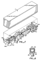
- Fig. 1 shows the chassis 10 in perspective and configured for towing by a truck tractor 12.
- a standard shipping container 11 is shown above and ready for mounting to chassis 10.
- the present invention includes a fifth wheel assembly 14 connected to a rear wheel assembly 15 by an extendible stinger 22.
- Fifth wheel assembly 15 is coupled to truck tractor 12 at fifth wheel 13.
- Such fifth wheel arrangements are well known in the art and have become a standard in the trucking industry.
- Fifth wheel assembly 14 rests on truck tractor rear wheels 16 when the chassis is configured to be towed to thereby transport a container.
- the fifth wheel assembly may also be supported by a retractable landing gear 21.
- Rear wheel assembly 15 receives a rear portion of container 11 and includes wheels 17 upon which the container and assembly rides. Spacing of the fifth wheel assembly from the rear wheel assembly is a function of the extent of extendible stinger 22.
- the stinger is complementary to and fits within channels 28 and 29 of the fifth wheel and rear wheel assemblies, respectively.
- An adjusting device 23 is provided for drawing the stinger into channel 28 or removing therefrom. In this way, the spacing between the fifth wheel assembly and rear wheel assembly can be changed thereby allowing the chassis to accommodate containers of various sizes.
- a similar adjusting device is included on channel 29 to correspondingly draw the stinger into and withdraw the stinger from the channel.
- Container 11 is of an industry standard type and includes front mounting sockets 30 and rear mounting sockets 31 that are configured for engagement with complementary pins located on the fifth wheel and rear wheel assemblies.
- the fifth wheel assembly includes cross members 18 and 19 having pins 24 and 25 attached thereto; the rear wheel assembly includes cross member 20 having pins 26 attached thereto.
- the present invention accommodates various sizes of containers according to the extension of stinger 22 and, in this embodiment of the invention, also according to the location of the front container pins in locking engagement with the pins on cross member 18 (pins 24) or cross member 19 (pins 25). Such arrangement is explained more fully below in the discussion of Fig. 3a.
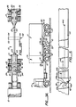
- Fig. 2a is a top plan view of the present invention showing stinger 22 retracted within channel members 28 and 29. Such a configuration is typical for trailers of between 20 and 24 feet in length. It can be seen from Figs. 1 and 2a that pins 24-26 are of an industry standard type for use with such industry standard containers. The pins, once engaged with the complementary container sockets, are operable to securely lock the container to the chassis for safe transport from point of origin to point of destination.
- Fig. 2b is a top plan view of the present invention showing stinger 22 extended from channels 28 and 29. Such arrangement is typically applicable for containers up to 40 feet in length. Operation of the invention is clearly seen when comparing Fig. 2a (stinger 22 retracted) with Fig. 2b (stinger 22 extended). Figs. 3a and 3b likewise show in side elevational format the retracted (Fig. 3a) and extended (Fig. 3b) configurations of the present invention.
- Fig. 3a is a side elevational view of the present invention showing a 20-foot container 11 mounted to chassis 10 and showing in phantom a 23-foot container lla mounted to said chassis.
- the Fig. additionally shows landing gear 20 in more detail including a supporting strut 32 and a landing gear footing 33.
- landing gear arrangements are well known for standard trucking equipment.
- the fifth wheel assembly and the rear wheel assembly provide a coplanar upper surface corresponding to the flat bottom surface llb of the container.
- the present invention provides a flat, horizontal planar region extending from the fifth wheel rearwardly, In this way, the present invention provides a simplified chassis which departs from typical "goose-neck" container chassis arrangements.
- Fig. 3a also shows a locking mechanism 34 for securing the stinger at a selected extent corresponding to that necessary for the length of container being transported. Locking device 34 is discussed in more detail below. It should be noted in Fig. 3a that for containers of the 20-foot size (11) and 23-foot size (lla) stinger 22 is in its minimum extended position. For this reason, cross members 18 and 19 are provided - cross member 18 for 23-foot containers and cross member 19 for 20-foot containers. Such arrangement is desirable in the embodiment of this invention to maintain an even distribution of container weight over the container supporting wheels 16/17.
- FIG. 2b wherein cross member 52 is shown including two sets of pins 53 and 54 by which pins 54 receive the front socket portion from the front end of a first container and pins 53 receive the rear socket portion of the rear end of another container.
- Fig. 3b shows the present invention configured for transporting a 40-foot chassis.
- the present invention requires adjustable extension of stinger 22 for all containers greater than 23 feet in length.
- a 40-foot container spans from cross member 20 to cross member 18, thereby covering cross member 19.
- pins 25 mounted to cross member 19 are of a hinged or retractable type well known in the industry. In this way, a large container of up to 40 feet may be placed covering cross member 19 and yet pins 25 are retracted out of the way so as to prevent interference with the secure mounting of the container to the chassis at pins 24 and 26 located on cross members 18 and 19, respectively.
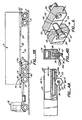
- Adjusting mechanism 23 is shown in more detail in Figs. 4a and 4b.
- a crank 36 is shown coupled to a pinion 37 including a set of pinion teeth 37a which engage within rack 38 and are complementary to rack teeth 38a. Accordingly, cranking motion of crank 36 draws stinger 22 into channel 28 or pushes stinger 22 out from channel 28. In this way, the spacing between the fifth wheel assembly and rear wheel assembly is readily adjusted.
- a hand crank 36a is shown as a portion of crank 36 in Fig. 4b, which is a cross-sectional view of the rack and pinion assembly. It can be seen in Fig. 4b that channel 28 is formed as a void within a bolster- like member into which stinger 22 firmly and snugly, yet movably, fits. A track portion 39 is included for receiving and mounting rack 38. Crank and pinion assembly 36/37 are held to channel member 28 by a bracket 40.
- a hand crank is shown as the adjusting means in this embodiment of the invention, other such engines may be provided. For example, a hydraulic, pneumatic, or electric motor can be provided for extending and retracting stinger 22.
- adjusting mechanism 23 can be provided at both the fifth wheel assembly and the rear wheel assembly, or it can be provided at either assembly as is suited for the application to which the present invention is put.
- the adjusting assembly can also be dispensed with altogether in some embodiments of the invention.
- Locking assembly 34 is shown is more detail in Figs. 5 and 6.
- stinger 22 is shown including a plurality of staggered apertures 44b-44d, said apertures being staggered from center and being located at different extensions along stinger 22.
- Each of said apertures is located at a position corresponding to a standard amount of extension, e.g. for 30-foot containers, 35-foot containers, 40-foot containers.
- a pin plate 42 is shown mounted to channel member 28 and including a plurality of apertures therein 43a-43d. Each aperture through pin plate 42 coincides with a corresponding aperture in stinger 22. Thus, aperture 43b through pin plate 42 coincides with aperture 44b through stinger 22 when a certain amount of desired extension is obtained.
- each stinger aperture determines the length of the chassis, which corresponds to the length of container to be carried. When the aperture is lined up with its corresponding aperture in plate 42, a pin is inserted therethrough and the stinger is locked in position for transportation of the container.
- a locking means 34 is shown associated with channel member 28, a similar locking means can also be associated with channel member 29 in addition to or instead of that associated with channel member 28.
- Fig. 6 shows a perspective in partial cross- section of a locking pin inserted through aperture 43 in channel member 28 for engagement with aperture 44 in stinger 22.
- Pin 46 includes a knob portion 48 by which the pin may be pulled outwardly to release it from engagement with aperture 44 and also includes a pin point 49 that engages with aperture 44 to lock stinger 22 in a selected position with channel member 28.
- Pin 46 in this embodiment of the invention is biased by a bias member, which may be a spring 47.
- the spring pushes outwardly against a pin shoulder portion 50 and pushes in an opposite direction against a shoulder portion 51 within aperture 43: In this way, the pin is set to lock into position as aperture 44 moves within alignment about pin point 49.
- the stinger automatically locks in position when a desired chassis length is obtained.
- locking means 34 includes pin arrangement 46, other such locking arrangements can be used in the present invention, such as cotter pins, bolts.
- FIG. 7 An alternative embodiment of the invention is shown in perspective view in Fig. 7.
- the chassis shown in perspective, has a rear wheel assembly 55 including wheels 72 and a fifth wheel assembly 56 including a fifth wheel hitch 71. Wheels 74 are shown having the spaced relation to fifth wheel assembly 56 that they would have if a towing tractor were coupled to the chassis.
- Fifth wheel assembly 56 also includes a landing gear 62 for supporting the chassis and any container load it is carrying when a towing tractor is not coupled to the chassis.
- landing gear 62 is shown having a support 73a in a retracted position; support 73b (shown in phantom) shows an extended, chassis supporting position of the landing gear.
- An elongate extensible stinger 57 is shown having two telescoping sections 58/59. The sections are arranged so that section 58 is readily recessed into fifth wheel assembly 56 as selected by stinger locking control 60.
- the locking control shown is of the type described above or may be of a similar type but including a hydraulic, pneumatic, or electrically operated release mechanism such that locking mechanism operation may be initiated remotely from the cab of the truck tractor or at any other convenient remote location.
- Second stinger section 59 is of lesser dimensions than stinger section 58 and, accordingly, readily telescopes into and out of first stinger section 58 as desired and as controlled by lock mechanism 61.
- lock mechanism 61 may be of the mechanical type described herein or may be of a power assisted type.
- Gathering surfaces 64a/b and 65a/b are provided on fifth wheel assembly 56 and rear wheel assembly 55, respectively.
- the gathering surfaces or pockets are flared, substantially vertical extensions at the corners of the fifth wheel and rear wheel assemblies and serve to guide a container into proper orientation with the chassis when the container is lowered to the chassis as shown in Fig. 7. Once guided into proper orientation with the chassis, the container is readily fastened thereto by industry standard locking bolts, described above.
- a marker light assembly 66 is included fastened to an underside portion of first stinger section 58 and having a light bar 67 and light 68.
- the light is provided to meet highway department requirements, where applicable.
- Light assembly 66 is operated by electrical power supplied, along with pressurized air, by cables 69. Power for the backup, rear, and brake lights, and air for the rear wheel assembly brakes are also supplied via cables 69.
- the cables are attached to extensible stinger 57 by means of hangers 70a-70f and are arranged in an accordian-like fashion. Accordingly, extending or shortening the chassis length is accomplished without having to lengthen or shorten or otherwise adjust the cables that provide air and electrical power from the truck tractor to the chassis and container assemblies.
- the elongated stinger may be provided in any number of sections as is convenient for the type and size range of containers being transported by the extensible chassis. Because the stinger sections telescope into and out of each other, there is a possibility of wear between the stinger sections, resulting from movement between the fifth wheel and rear wheel assemblies. Most of this movement, which consists of various components of stress and torsion, is damped or otherwise absorbed by the container itself. That is, when the container is fitted to the chassis, the chassis/container combination becomes a unitary assembly.
- the present invention exploits the rigid property of the container to provide a continuously rigid link between the fifth wheel and rear wheel assemblies.
- the combination of the container and the fifth wheel and rear wheel assemblies carries the full load weight and transmits most transport stress from the fifth wheel assembly to the rear wheel assembly through the container itself.
- This arrangement eliminates the need for heavy gauge stinger construction and allows the stinger to be formed in a plurality of sections, resulting in a lighter and more easily adjustable chassis.
- the present invention includes a clamp assembly 80 consisting of a clamp plate 81 and a piston 82, powered by a pneumatic, electric, or hydraulic power source 83. It is convenient in the exemplary embodiment of the invention to use a pneumatic power source which can be powered from the tractor truck's air line However, any source of power, including an electrical device such as a solenoid, can be used to power piston 82.
- the piston When the chassis is adjusted to accommodate various size shipping containers, the piston is withdrawn and plate 81 is released, allowing the stinger to be inserted or withdrawn from its associated wheel assembly or telescoping stinger portion.
- piston 82 When piston 82 is extended, plate 81 is forced into compressive abutment with a bottom surface of the stinger portion extending into and associated with clamp assembly 80. As a result, the stinger is locked into place within a surrounding portion of its associated wheel assembly or telescoping stinger portion, thus preventing torsional or stress-induced movement of the stinger member within its associated wheel assembly or telescoping stinger portion.
- the present invention provides clamp assembly 80 to take up slack along the stinger between the wheel assemblies.
- the life of the chassis is extended by the prevention of sagging at one end or the other of the chassis. This prevents wear and tear on the contact and moving points within the chassis.
- Prevention of such wear between the wheel assemblies and the stinger is very critical in any chassis which carries containers of the type described herein. If the planar relationship between the fifth wheel assembly and rear wheel assembly were disturbed due to wear, such that one assembly sagged or was out of alignment with another of the assemblies, it would not be possible to properly engage the container with the locking bolts on the chassis. As a result, the chassis would be useless for the transportation of containers.
- Including clamp assembly 80 in the present invention eliminates sagging and wear along and about the stinger assembly and thus prevents misalignment between the fifth wheel and rear wheel assemblies from occurring.
- additional cross members can be added to rear wheel assembly 15 in lieu of, or in addition to, those on fifth wheel assembly 14.
- An additional cross member can be added at a central portion of stinger 22 by which two containers of varying lengths can be accommodated by the present invention.
- the rear wheel assembly is adjusted for spacing from the additional, center cross member so that a container carried on that portion is properly positioned from the rear wheel cross member to the stinger cross member.
- the spacing between the fifth wheel cross member and the stinger cross member is independently adjusted to accommodate the container placed therebetween.
- Additional embodiments of the invention can provide devices other than a rack and pinion for adjusting the extent of the stinger or can dispense with adjusting means entirely.
- various types of locking arrangements can be employed. Therefore, the scope of the invention should be limited only by the breadth of the claims.
Landscapes
- Engineering & Computer Science (AREA)
- Transportation (AREA)
- Mechanical Engineering (AREA)
- Chemical & Material Sciences (AREA)
- Combustion & Propulsion (AREA)
- Body Structure For Vehicles (AREA)
Priority Applications (1)
| Application Number | Priority Date | Filing Date | Title |
|---|---|---|---|
| AT83109982T ATE25627T1 (de) | 1983-05-03 | 1983-10-05 | Ausziehbarer rahmen zum transport von containern. |
Applications Claiming Priority (4)
| Application Number | Priority Date | Filing Date | Title |
|---|---|---|---|
| US06/491,142 US4561671A (en) | 1983-05-03 | 1983-05-03 | Extensible chassis for hauling containers |
| US491142 | 1983-05-03 | ||
| US06/529,073 US4566714A (en) | 1983-05-03 | 1983-09-02 | Universal chassis for hauling containers |
| US529073 | 1983-09-02 |
Publications (2)
| Publication Number | Publication Date |
|---|---|
| EP0123723A1 true EP0123723A1 (de) | 1984-11-07 |
| EP0123723B1 EP0123723B1 (de) | 1987-03-04 |
Family
ID=27050322
Family Applications (1)
| Application Number | Title | Priority Date | Filing Date |
|---|---|---|---|
| EP83109982A Expired EP0123723B1 (de) | 1983-05-03 | 1983-10-05 | Ausziehbarer Rahmen zum Transport von Containern |
Country Status (9)
| Country | Link |
|---|---|
| US (1) | US4566714A (de) |
| EP (1) | EP0123723B1 (de) |
| KR (1) | KR850000330A (de) |
| AU (1) | AU568645B2 (de) |
| BR (1) | BR8305677A (de) |
| CA (1) | CA1224224A (de) |
| DE (1) | DE3369932D1 (de) |
| HK (1) | HK33788A (de) |
| PH (1) | PH24286A (de) |
Cited By (9)
| Publication number | Priority date | Publication date | Assignee | Title |
|---|---|---|---|---|
| EP0201615A1 (de) * | 1985-05-14 | 1986-11-20 | X-TEN Corporation | Anhänger für in Containern transportierte Ladung |
| GB2207399A (en) * | 1987-07-28 | 1989-02-01 | Kai Chea Ng | Modified container trailer |
| EP0206306A3 (de) * | 1985-06-24 | 1989-03-29 | X-TEN Corporation | Rahmen mit einem ausziehbaren gelenkigen Längsträger |
| NL9302012A (nl) * | 1993-11-19 | 1994-04-05 | Cornelis Gerardus Strien | Trailer voor vervoer van ISO-norm containers. |
| US5542807A (en) * | 1994-05-03 | 1996-08-06 | Galbreath Incorporated | Vehicle mounted, variable length hook hoist |
| US5803699A (en) * | 1996-11-12 | 1998-09-08 | Capitol Tool And Die Co. | Apparatus and method for loading and unloading containers |
| DE29910693U1 (de) * | 1999-03-06 | 2000-08-03 | R. Metternich Metallbau GmbH, 21107 Hamburg | Ausschub- oder Ausziehvorrichtung für ein Container-Chassis |
| DE10315145B3 (de) * | 2003-04-03 | 2004-11-04 | Hans Kotschenreuther | Langfahrzeug, insbesondere Sattelauflieger |
| NL1025455C2 (nl) * | 2004-02-10 | 2005-08-12 | Vlastuin Rolling Equipment B V | Verrijdbare draagconstructie. |
Families Citing this family (30)
| Publication number | Priority date | Publication date | Assignee | Title |
|---|---|---|---|---|
| US4665834A (en) * | 1985-08-16 | 1987-05-19 | Sea-Land Service Inc. | Apparatus for intermodal transport of highway containers |
| US4958845A (en) * | 1988-09-16 | 1990-09-25 | Parks Donald J | Extendable trailer apparatus |
| US5255933A (en) * | 1992-02-03 | 1993-10-26 | Calkins Manufacturing Company | Weight distributing hull and keel support for boat trailer frames |
| US5572837A (en) * | 1994-08-05 | 1996-11-12 | The Will-Burt Company | Pneumatic telescoping mast |
| US5573360A (en) * | 1995-03-16 | 1996-11-12 | Bennett; Richard C. | Pallet latching mechanism |
| DE29505611U1 (de) * | 1995-03-31 | 1996-08-01 | Meusburger Fahrzeugbau GmbH, 94535 Eging | Sattelschlepperanhänger |
| US6290377B1 (en) | 1996-01-16 | 2001-09-18 | The Will-Burt Company | Pneumatically telescoping mast having DC operated lighting and pivoting means |
| US5794960A (en) * | 1996-02-23 | 1998-08-18 | Stoughton Trailers, Inc. | Chassis with convertible gooseneck |
| CA2241385C (en) * | 1998-07-29 | 2007-01-09 | N. Royce Curry | Automotive transport tractors, semi-trailers, trailers and combinations thereof |
| US6186533B1 (en) * | 2000-01-28 | 2001-02-13 | Cormetal Of Usa, Inc. | Monotubular chassis for trailers |
| DE20004167U1 (de) * | 2000-02-07 | 2001-06-28 | Botzenhart, Alfred, 87781 Ungerhausen | Fahrzeug |
| US6484456B1 (en) | 2000-02-09 | 2002-11-26 | Featherstone Teamed Industries, Inc. | Telescoping mast assembly |
| US6546677B1 (en) | 2000-02-09 | 2003-04-15 | Featherstone Teamed Industries, Inc. | Telescoping mast assembly |
| GB0004349D0 (en) * | 2000-02-25 | 2000-04-12 | Morgan Motor Company Limited | Improvements relating to vehicles |
| GB0204687D0 (en) * | 2002-02-28 | 2002-04-17 | Extec Ind Plc | Tractor unit/trailer combination for suspended transport of equipment |
| US8534735B2 (en) * | 2003-06-05 | 2013-09-17 | The Riverbank, Llc | Apparatus for configuring the interior space of a vehicle |
| US6969104B2 (en) * | 2003-09-16 | 2005-11-29 | Green Charles T | Adjustable length chassis |
| US20060181063A1 (en) * | 2005-02-17 | 2006-08-17 | Eddings William L | Sliding goose neck trailer with sliding load bars |
| US20090261546A1 (en) * | 2008-04-16 | 2009-10-22 | Rowland Leroy J | Stackable trailers for transporting containers |
| US20090278326A1 (en) * | 2008-04-16 | 2009-11-12 | Stackable Chassis International, Llc | Kits, Components and Stackable Trailers for Transporting Containers |
| JP2010176277A (ja) * | 2009-01-28 | 2010-08-12 | Sanyo Electric Co Ltd | データ転送システム |
| USD635064S1 (en) | 2009-06-17 | 2011-03-29 | Stackable Chassis International, Llc | Landing gear adapter for trailer chassis |
| USD635495S1 (en) | 2009-06-17 | 2011-04-05 | Stackable Chassis International, Llc | Saddle for trailer chassis |
| USD642097S1 (en) | 2009-06-17 | 2011-07-26 | Stackable Chassis International, Inc. | Saddle for trailer chassis |
| US9555831B1 (en) * | 2013-03-14 | 2017-01-31 | Gale Dahlstrom | Tractor-trailer with convertible steering arrangement |
| US9527539B1 (en) * | 2015-08-13 | 2016-12-27 | Duo Lift Manufacturing Co., Inc. | Swather header transport trailer |
| CA2987421C (en) | 2016-12-20 | 2024-06-25 | Equipement Max-Atlas International Inc. | Extendable trailer for freight containers |
| KR102135473B1 (ko) * | 2020-01-15 | 2020-07-17 | 에이스캠퍼(주) | 조립식캠핑카의 차량프레임과 서브프레임의 장착장치 |
| WO2022032366A1 (pt) * | 2020-08-14 | 2022-02-17 | American Bull Implementos Rodoviários Sa | Semirreboque para transporte de containers |
| US20240109615A1 (en) * | 2022-10-03 | 2024-04-04 | Master Solutions, Inc. | Stretch Trailer With Pivotable Roller Mechanism |
Citations (5)
| Publication number | Priority date | Publication date | Assignee | Title |
|---|---|---|---|---|
| FR1084747A (fr) * | 1953-06-15 | 1955-01-24 | Perfectionnement aux remorques de grandes longueurs | |
| FR1522677A (fr) * | 1966-05-06 | 1968-04-26 | Dorsey Trailers | Accouplement de deux semi-remorques |
| GB1231404A (de) * | 1967-11-09 | 1971-05-12 | ||
| FR2264705A1 (en) * | 1974-03-18 | 1975-10-17 | Benalu Sa | Adjustable semi-trailer for container transport - has three section telescopic chassis with two alternative steering pivots |
| DE3037081A1 (de) * | 1977-12-20 | 1982-05-06 | Alfons 7321 Schlat Seibold | Lastfahrzeug |
Family Cites Families (16)
| Publication number | Priority date | Publication date | Assignee | Title |
|---|---|---|---|---|
| US2119800A (en) * | 1937-05-17 | 1938-06-07 | Roy H Tull | Telescoping extension for trucks and trailers |
| US2452358A (en) * | 1945-02-22 | 1948-10-26 | Long Fred Joe Dc | Axle and fifth wheel assembly for farm wagons |
| US2413910A (en) * | 1945-10-18 | 1947-01-07 | Diard Ray | Logging trailer |
| US2631885A (en) * | 1950-05-08 | 1953-03-17 | Thomas J Ault | Container fastening apparatus for transport vehicles |
| US2657939A (en) * | 1951-03-27 | 1953-11-03 | Monroe B Beebe | Rocking axle with steerable stub axles |
| US2856087A (en) * | 1957-01-08 | 1958-10-14 | Clarence R Steber | Telescopic boom boat trailer |
| US2900194A (en) * | 1957-03-08 | 1959-08-18 | Lay Manford Samuel De | Load equalizer for trailer |
| US3348711A (en) * | 1965-06-28 | 1967-10-24 | Emery T Gove | Straddle type carrier |
| US3451573A (en) * | 1967-07-03 | 1969-06-24 | Pacific Oxygen Co | Transporting system |
| US3486787A (en) * | 1967-10-09 | 1969-12-30 | Trailco Mfg & Sales Co | Retractable lock |
| FR1561208A (de) * | 1967-12-21 | 1969-03-28 | ||
| US3552325A (en) * | 1968-01-31 | 1971-01-05 | Gen Am Transport | Freight transportation system and components thereof |
| US3508762A (en) * | 1968-03-22 | 1970-04-28 | Clark Equipment Co | Container chassis |
| FR2098720A5 (de) * | 1970-07-24 | 1972-03-10 | Petetin Paul | |
| US4080080A (en) * | 1977-02-16 | 1978-03-21 | American Hospital Supply Corporation | Adjustable leg assembly |
| US4169611A (en) * | 1977-03-07 | 1979-10-02 | Smith Dentis M | Trailer tongue extension |
-
1983
- 1983-09-02 US US06/529,073 patent/US4566714A/en not_active Expired - Fee Related
- 1983-10-05 EP EP83109982A patent/EP0123723B1/de not_active Expired
- 1983-10-05 DE DE8383109982T patent/DE3369932D1/de not_active Expired
- 1983-10-12 PH PH29684A patent/PH24286A/en unknown
- 1983-10-14 BR BR8305677A patent/BR8305677A/pt not_active IP Right Cessation
- 1983-10-24 KR KR1019830005026A patent/KR850000330A/ko not_active Ceased
-
1984
- 1984-05-02 CA CA000453310A patent/CA1224224A/en not_active Expired
- 1984-05-02 AU AU27589/84A patent/AU568645B2/en not_active Ceased
-
1988
- 1988-05-02 HK HK337/88A patent/HK33788A/xx unknown
Patent Citations (5)
| Publication number | Priority date | Publication date | Assignee | Title |
|---|---|---|---|---|
| FR1084747A (fr) * | 1953-06-15 | 1955-01-24 | Perfectionnement aux remorques de grandes longueurs | |
| FR1522677A (fr) * | 1966-05-06 | 1968-04-26 | Dorsey Trailers | Accouplement de deux semi-remorques |
| GB1231404A (de) * | 1967-11-09 | 1971-05-12 | ||
| FR2264705A1 (en) * | 1974-03-18 | 1975-10-17 | Benalu Sa | Adjustable semi-trailer for container transport - has three section telescopic chassis with two alternative steering pivots |
| DE3037081A1 (de) * | 1977-12-20 | 1982-05-06 | Alfons 7321 Schlat Seibold | Lastfahrzeug |
Cited By (11)
| Publication number | Priority date | Publication date | Assignee | Title |
|---|---|---|---|---|
| EP0201615A1 (de) * | 1985-05-14 | 1986-11-20 | X-TEN Corporation | Anhänger für in Containern transportierte Ladung |
| EP0206306A3 (de) * | 1985-06-24 | 1989-03-29 | X-TEN Corporation | Rahmen mit einem ausziehbaren gelenkigen Längsträger |
| GB2207399A (en) * | 1987-07-28 | 1989-02-01 | Kai Chea Ng | Modified container trailer |
| NL9302012A (nl) * | 1993-11-19 | 1994-04-05 | Cornelis Gerardus Strien | Trailer voor vervoer van ISO-norm containers. |
| EP0649772A1 (de) * | 1993-11-19 | 1995-04-26 | Cornelis Gerardus Strien | Sattelauflieger, insbesondere für Containertransport |
| US5542807A (en) * | 1994-05-03 | 1996-08-06 | Galbreath Incorporated | Vehicle mounted, variable length hook hoist |
| US5803699A (en) * | 1996-11-12 | 1998-09-08 | Capitol Tool And Die Co. | Apparatus and method for loading and unloading containers |
| DE29910693U1 (de) * | 1999-03-06 | 2000-08-03 | R. Metternich Metallbau GmbH, 21107 Hamburg | Ausschub- oder Ausziehvorrichtung für ein Container-Chassis |
| DE10315145B3 (de) * | 2003-04-03 | 2004-11-04 | Hans Kotschenreuther | Langfahrzeug, insbesondere Sattelauflieger |
| NL1025455C2 (nl) * | 2004-02-10 | 2005-08-12 | Vlastuin Rolling Equipment B V | Verrijdbare draagconstructie. |
| EP1564117A1 (de) * | 2004-02-10 | 2005-08-17 | Vlastuin Rolling Equipment B.V. | Mobile Stutzstruktur |
Also Published As
| Publication number | Publication date |
|---|---|
| US4566714A (en) | 1986-01-28 |
| KR850000330A (ko) | 1985-02-26 |
| EP0123723B1 (de) | 1987-03-04 |
| BR8305677A (pt) | 1985-03-05 |
| HK33788A (en) | 1988-05-13 |
| CA1224224A (en) | 1987-07-14 |
| DE3369932D1 (en) | 1987-04-09 |
| AU2758984A (en) | 1984-11-08 |
| PH24286A (en) | 1990-05-29 |
| AU568645B2 (en) | 1988-01-07 |
Similar Documents
| Publication | Publication Date | Title |
|---|---|---|
| US4566714A (en) | Universal chassis for hauling containers | |
| US4561671A (en) | Extensible chassis for hauling containers | |
| US4597712A (en) | Trailer apparatus for transporting vehicles and other cargo | |
| US5183375A (en) | Container stacking apparatus | |
| US4986705A (en) | Stackable freight container for holding stacked chassis | |
| US4343401A (en) | Automobile containerized shipment support kit | |
| US5401129A (en) | Trailer for hauling metal coils | |
| US3567252A (en) | Vehicle formed by couplable container means with demountable couplable adapter frames | |
| US6309153B1 (en) | Intermodal transfer trailer | |
| CN1030390A (zh) | 可闭合的集装箱型的货箱装置 | |
| US3144838A (en) | Container support device for a railway car | |
| US20060269379A1 (en) | Chassis shipping unit | |
| US8708626B2 (en) | Freight carrier | |
| US7717656B2 (en) | Attachment device for moving cargo containers | |
| US4792268A (en) | Apparatus for supporting vehicles and the like | |
| US20250100792A1 (en) | Method and apparatus for increasing the volume of materials transported in a shipping container, truck, and/or semi trailer | |
| US5074725A (en) | Well car trailer adaptor | |
| JP3724588B2 (ja) | 上部構造付きボディ | |
| US4413943A (en) | Method and apparatus for loading and unloading a lengthy object from a transport vehicle | |
| US1611882A (en) | System and apparatus for handling freight | |
| US4496187A (en) | Trailer construction | |
| US3070041A (en) | Highway-railway transportation system and apparatus | |
| KR100476029B1 (ko) | 수평으로 실린 화물 유닛을 선박에 체결하기 위한 방법 및장치 | |
| EP0153023B1 (de) | Gerät zum Halten von Fahrzeugen und dergleichen | |
| US11214436B2 (en) | Transport platform |
Legal Events
| Date | Code | Title | Description |
|---|---|---|---|
| PUAI | Public reference made under article 153(3) epc to a published international application that has entered the european phase |
Free format text: ORIGINAL CODE: 0009012 |
|
| AK | Designated contracting states |
Designated state(s): AT BE CH DE FR GB IT LI LU NL SE |
|
| 17P | Request for examination filed |
Effective date: 19850412 |
|
| RAP1 | Party data changed (applicant data changed or rights of an application transferred) |
Owner name: X-TEN CORPORATION |
|
| GRAA | (expected) grant |
Free format text: ORIGINAL CODE: 0009210 |
|
| AK | Designated contracting states |
Kind code of ref document: B1 Designated state(s): AT BE CH DE FR GB IT LI LU NL SE |
|
| REF | Corresponds to: |
Ref document number: 25627 Country of ref document: AT Date of ref document: 19870315 Kind code of ref document: T |
|
| ITF | It: translation for a ep patent filed | ||
| REF | Corresponds to: |
Ref document number: 3369932 Country of ref document: DE Date of ref document: 19870409 |
|
| ET | Fr: translation filed | ||
| PLBE | No opposition filed within time limit |
Free format text: ORIGINAL CODE: 0009261 |
|
| STAA | Information on the status of an ep patent application or granted ep patent |
Free format text: STATUS: NO OPPOSITION FILED WITHIN TIME LIMIT |
|
| 26N | No opposition filed | ||
| ITTA | It: last paid annual fee | ||
| EPTA | Lu: last paid annual fee | ||
| PGFP | Annual fee paid to national office [announced via postgrant information from national office to epo] |
Ref country code: LU Payment date: 19941001 Year of fee payment: 12 |
|
| PGFP | Annual fee paid to national office [announced via postgrant information from national office to epo] |
Ref country code: FR Payment date: 19941007 Year of fee payment: 12 |
|
| PGFP | Annual fee paid to national office [announced via postgrant information from national office to epo] |
Ref country code: AT Payment date: 19941013 Year of fee payment: 12 |
|
| PGFP | Annual fee paid to national office [announced via postgrant information from national office to epo] |
Ref country code: SE Payment date: 19941014 Year of fee payment: 12 Ref country code: GB Payment date: 19941014 Year of fee payment: 12 |
|
| PGFP | Annual fee paid to national office [announced via postgrant information from national office to epo] |
Ref country code: BE Payment date: 19941020 Year of fee payment: 12 |
|
| PGFP | Annual fee paid to national office [announced via postgrant information from national office to epo] |
Ref country code: DE Payment date: 19941024 Year of fee payment: 12 |
|
| PGFP | Annual fee paid to national office [announced via postgrant information from national office to epo] |
Ref country code: CH Payment date: 19941025 Year of fee payment: 12 |
|
| PGFP | Annual fee paid to national office [announced via postgrant information from national office to epo] |
Ref country code: NL Payment date: 19941031 Year of fee payment: 12 |
|
| EAL | Se: european patent in force in sweden |
Ref document number: 83109982.5 |
|
| PG25 | Lapsed in a contracting state [announced via postgrant information from national office to epo] |
Ref country code: LU Free format text: LAPSE BECAUSE OF NON-PAYMENT OF DUE FEES Effective date: 19951005 Ref country code: GB Effective date: 19951005 Ref country code: AT Effective date: 19951005 |
|
| PG25 | Lapsed in a contracting state [announced via postgrant information from national office to epo] |
Ref country code: SE Effective date: 19951006 |
|
| PG25 | Lapsed in a contracting state [announced via postgrant information from national office to epo] |
Ref country code: LI Effective date: 19951031 Ref country code: CH Effective date: 19951031 Ref country code: BE Effective date: 19951031 |
|
| BERE | Be: lapsed |
Owner name: X-TEN CORP. Effective date: 19951031 |
|
| PG25 | Lapsed in a contracting state [announced via postgrant information from national office to epo] |
Ref country code: NL Effective date: 19960501 |
|
| GBPC | Gb: european patent ceased through non-payment of renewal fee |
Effective date: 19951005 |
|
| REG | Reference to a national code |
Ref country code: CH Ref legal event code: PL |
|
| PG25 | Lapsed in a contracting state [announced via postgrant information from national office to epo] |
Ref country code: FR Effective date: 19960628 |
|
| EUG | Se: european patent has lapsed |
Ref document number: 83109982.5 |
|
| PG25 | Lapsed in a contracting state [announced via postgrant information from national office to epo] |
Ref country code: DE Effective date: 19960702 |
|
| NLV4 | Nl: lapsed or anulled due to non-payment of the annual fee |
Effective date: 19960501 |
|
| REG | Reference to a national code |
Ref country code: FR Ref legal event code: ST |