EP0123744A1 - Contrôle des changements des quantités de débit de fluide d'une pluralité d'écoulements de fluide - Google Patents
Contrôle des changements des quantités de débit de fluide d'une pluralité d'écoulements de fluide Download PDFInfo
- Publication number
- EP0123744A1 EP0123744A1 EP83302436A EP83302436A EP0123744A1 EP 0123744 A1 EP0123744 A1 EP 0123744A1 EP 83302436 A EP83302436 A EP 83302436A EP 83302436 A EP83302436 A EP 83302436A EP 0123744 A1 EP0123744 A1 EP 0123744A1
- Authority
- EP
- European Patent Office
- Prior art keywords
- fluid
- flow
- gas
- rate
- streams
- Prior art date
- Legal status (The legal status is an assumption and is not a legal conclusion. Google has not performed a legal analysis and makes no representation as to the accuracy of the status listed.)
- Granted
Links
Images
Classifications
-
- C—CHEMISTRY; METALLURGY
- C09—DYES; PAINTS; POLISHES; NATURAL RESINS; ADHESIVES; COMPOSITIONS NOT OTHERWISE PROVIDED FOR; APPLICATIONS OF MATERIALS NOT OTHERWISE PROVIDED FOR
- C09K—MATERIALS FOR MISCELLANEOUS APPLICATIONS, NOT PROVIDED FOR ELSEWHERE
- C09K15/00—Anti-oxidant compositions; Compositions inhibiting chemical change
- C09K15/04—Anti-oxidant compositions; Compositions inhibiting chemical change containing organic compounds
- C09K15/30—Anti-oxidant compositions; Compositions inhibiting chemical change containing organic compounds containing heterocyclic ring with at least one nitrogen atom as ring member
-
- G—PHYSICS
- G01—MEASURING; TESTING
- G01F—MEASURING VOLUME, VOLUME FLOW, MASS FLOW OR LIQUID LEVEL; METERING BY VOLUME
- G01F1/00—Measuring the volume flow or mass flow of fluid or fluent solid material wherein the fluid passes through a meter in a continuous flow
-
- G—PHYSICS
- G01—MEASURING; TESTING
- G01F—MEASURING VOLUME, VOLUME FLOW, MASS FLOW OR LIQUID LEVEL; METERING BY VOLUME
- G01F1/00—Measuring the volume flow or mass flow of fluid or fluent solid material wherein the fluid passes through a meter in a continuous flow
- G01F1/704—Measuring the volume flow or mass flow of fluid or fluent solid material wherein the fluid passes through a meter in a continuous flow using marked regions or existing inhomogeneities within the fluid stream, e.g. statistically occurring variations in a fluid parameter
Definitions
- the present invention relates to monitoring flow-rate changes of a plurality of fluid streams, in order to identify their source.
- the present invention provides a method of determining which fluid stream of a plurality of fluid streams flowing through respective conduits flows at a changed rate, the method comprising the steps of:
- the feature of the characteristic may be the concentration (including presence or absence) or proportion of at least one substance in each composite sample.
- concentration may be determined by any convenient technique, e.g. thermal or electrical conductivity, NMR, colour, dielectric properties, emission spectra, X-ray spectra, heat of combustion, inter alia.
- the fluid streams are all gaseous,the existence or concentration or proportion of at least one substance in each sample may be determined by gas chromatography techniques. Whichever technique (or combination of techniques) is employed, step (c) is preferably performed automatically by comparison with a library or database of the features of the characteristics of fluid streams.
- steps (a), (b) and (c) of the method of the invention are repeated, and the interval between repeats is preferably as short as possible having regard to the type of equipment employed to perform the method.
- Appropriate and meaningful data may be obtained from non-consecutive repeats, particularly when the time interval between repeats is relatively short in relation to the time periods over which the said feature of the characteristic changes or takes to change to a final or lined-out value from a changing or transient value.
- the fluid streams flow into a common conduit from their respective conduits, and the sampling point is at a location suitable for recovering substantially representative samples from the common conduit.
- the method of the invention further comprises the steps of :
- synchronizing means are employed to control the timing of steps (a), (b) and (d) so that the said composite samples and the corresponding monitored flow-rates are obtained at corresponding respective times and intervals.
- the let-down valve and the safety valve are both prone to leakage, and such leakage results in the unplanned loss of gases resulting in higher operating costs for the process unit.
- instal a flowmeter at or near each valve to determine the flow rate of vented gas from each unit into each pipe, the large numbers of pipes and valves makes this approach exceedingly expensive.
- the method and apparatus of the invention provide a relatively low-cost alternative which can be used reliably in all normal plant operating modes.
- composite gas samples are periodically withdrawn from the common conduit which receives gases piped from process units and other sources via respective pipes and supplies the gases to the flare.
- Each composite gas sample is compared with a preceding composite gas sample to determine whether or not the composition of the gas in the common conduit has changed. Any change in the composition of the gas in the common conduit is due to the presence of different amounts of gas from one or more process units as a result of the operating conditions in the process units and/or variations in the leakage of gas from the process units.
- By comparing the compositions of successive (bût not necessarily consecutive) composite gas samples it is possible to determine the composition of the gas which has caused the change in composition.
- composition of the gas which has caused the change is correlated with the compositions of known gases produced in the process units (e.g. from a library or database of such compositions) and it is thereby possible to identify the process unit which is responsible for the change in the gas composition in the common conduit.
- each composite gas sample is analyzed by a gas chromatography analyzer, and the latter may be linked to micro- processor/comparator equipment which compares each analysis with a preceding analysis.
- the comparison may be effected in such a manner that by suitable computing, the composition of the gas causing the change of composition is determined, and by drawing on a library or database of gas compositions, the source of the change of composition may be identified.
- the method of the invention may be partially or fully automated. In the latter case, the source of the change of gas composition may be recorded and/or displayed.
- suitable equipment is employed to monitor the flow rate of fluid in the common conduit from which the representative samples are taken, and changes in the flow-rate are correlated with changes in the composition (and/or any other feature of a characteristic) of the monitored fluid, as substantially representatively sampled.
- the concentration (c) of a respective component in the said one stream can be calculated from the equation ? where G 1 and G 2 are respectively the concentrations of the respective component in the total flow in the common conduit at the time of the flow rates Q 1 and Q 2 .
- the percentage analysis of the flare gas which is the gas mixture resulting from combining the separate gas streams from the pipes A to E, is determined by a gas chromatograph.
- composition of the gas stream which has caused the change can be calculated, as follows :
- composition of a gas stream consisting of components , 1, 6 and 7 which would produce the changed percentage compositions determined above is easily calculated as follows:
- the change in flare gas composition can be expected to be due to the addition of gas released from one process unit, and the additional released gas has a composition consisting of : 20% component 1, 40% component 6 and 40% component 7.
- the process unit from which the additional gas has been released can easily be identified and the operation of the process unit can be checked to ascertain the reason for the release and loss of gas, and,if possible, to change the operating conditions to reduce or eliminate the loss. It is evident from the data given in the first two tables that the additional gas in the flare gas is from pipe C, but. it will be appreciated that it is not necessary to determine the flow or composition of gas in any one of the pipes communicating with the common conduit of the flare.
- a compositional analysis of the total gas flow before and after a change in flow rate can be calculated using equation (1), given infra. Such a compositional analysis permits identification of the gas stream which has a changed flow-rate, and/or permits of verification of the identity of the gas stream as identified by the calculations given previously.
- the example refers only to 5 pipes which can supply the flare. In practice, there would be many more, typically 300 to 500 in a refinery. Moreover, there may be many more than 8 components of the flare gas. However, the skilled technologist will appreciate that it is necessary to monitor only those gas components which will be significant in identifying the process unit from which gas can be released to the flare.
- the invention is useful in monitoring the normal operation of process units.
- the normal monitoring system of the plant will be employed to identify and rectify the cause of the perturbation.
- the invention is applicable to streams other than gas streams, and can be applied to liquid streams and solid streams (e.g. mixtures of particulate solids), and any combination of at least two of gases, liquids and solids streams.
- liquid streams and solid streams e.g. mixtures of particulate solids
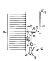
- waste and excess gases released from process units are burned in a flame 10 at the top of a flare stack 11.
- the waste gases are combined in a common conduit 12 for supply to the stack 11, and the conduit 12 receives gases from the process units via a plurality of respective pipes indicated generally by reference 13.
- the common conduit 12 may comprise a flowmeter 14 and a flow indicator 15 may display and/or record the flows measured by the flowmeter 14.
- Composite samples of gas are taken from the conduit 12 from a sampling point 16 via a valve 17 which is periodically (e.g. every 5 to 10 minutes) opened by a signal from a timing device (not shown) associated with gas analysis equipment 18.
- the gas analysis equipment 18 is suitably a gas chromatograph, and signals representative of the differential analysis of at least selected key components of successive (but not necessarily consecutive) gas samples are relayed either directly to an indicating and/or recording device 19 via line 20 and/or first to a comparator 21 which compares the signals with signals available from a database contained in a suitable memory device 22. The results of the operation of the comparator 21 are relayed to the recording and/or indicating device 19 (or to a separate, equivalent device) which indicates and/or records which process unit has caused a change in the composition of gas sampled at sampling point 16.
- the method of the invention is to be employed using equation (1) to identify, and/or verify the identity of, the stream whose flow-rate changes, the flow-rate in the common conduit 12, as detected by flowmeter 14, is relayed to a computer 23 which also receives gas composition data from the gas analysis equipment 18.
- the computer 23 is programmed to calculate the concentration of each component, or selected components, using equation (1).
- the flowmeter 14 is somewhat upstream of the sampling point 16.
- the equipment 18 is operated with an appropriate delay relative to the computer 23.
- the delay is governed by a synchronizing signal relayed to the equipment 18 from suitable means (not shown) associated either with the flowmeter 14 or the computer 23.
Landscapes
- Chemical & Material Sciences (AREA)
- Physics & Mathematics (AREA)
- Fluid Mechanics (AREA)
- General Physics & Mathematics (AREA)
- Engineering & Computer Science (AREA)
- Materials Engineering (AREA)
- Organic Chemistry (AREA)
- Sampling And Sample Adjustment (AREA)
Priority Applications (3)
| Application Number | Priority Date | Filing Date | Title |
|---|---|---|---|
| GB08135058A GB2109930B (en) | 1981-11-20 | 1981-11-20 | Monitoring the flow-rates of a plurality of fluid streams |
| DE8383302436T DE3375948D1 (en) | 1983-04-29 | 1983-04-29 | Monitoring the flow-rate changes of a plurality of fluid streams |
| EP83302436A EP0123744B1 (fr) | 1981-11-20 | 1983-04-29 | Contrôle des changements des quantités de débit de fluide d'une pluralité d'écoulements de fluide |
Applications Claiming Priority (2)
| Application Number | Priority Date | Filing Date | Title |
|---|---|---|---|
| GB08135058A GB2109930B (en) | 1981-11-20 | 1981-11-20 | Monitoring the flow-rates of a plurality of fluid streams |
| EP83302436A EP0123744B1 (fr) | 1981-11-20 | 1983-04-29 | Contrôle des changements des quantités de débit de fluide d'une pluralité d'écoulements de fluide |
Publications (2)
| Publication Number | Publication Date |
|---|---|
| EP0123744A1 true EP0123744A1 (fr) | 1984-11-07 |
| EP0123744B1 EP0123744B1 (fr) | 1988-03-09 |
Family
ID=26089102
Family Applications (1)
| Application Number | Title | Priority Date | Filing Date |
|---|---|---|---|
| EP83302436A Expired EP0123744B1 (fr) | 1981-11-20 | 1983-04-29 | Contrôle des changements des quantités de débit de fluide d'une pluralité d'écoulements de fluide |
Country Status (2)
| Country | Link |
|---|---|
| EP (1) | EP0123744B1 (fr) |
| GB (1) | GB2109930B (fr) |
Cited By (2)
| Publication number | Priority date | Publication date | Assignee | Title |
|---|---|---|---|---|
| WO1994027118A1 (fr) * | 1993-05-12 | 1994-11-24 | British Nuclear Fuels Plc | Mesure du debit d'un fluide |
| WO2000025097A1 (fr) * | 1998-10-28 | 2000-05-04 | Brulines Limited | Systeme et procede permettant de surveiller un debit de fluide |
Families Citing this family (1)
| Publication number | Priority date | Publication date | Assignee | Title |
|---|---|---|---|---|
| US10429067B2 (en) | 2016-11-30 | 2019-10-01 | Saudi Arabian Oil Company | Dynamic multi-legs ejector for use in emergency flare gas recovery system |
Citations (4)
| Publication number | Priority date | Publication date | Assignee | Title |
|---|---|---|---|---|
| US3036229A (en) * | 1959-12-24 | 1962-05-22 | Us Industries Inc | Well test programming system and programmer therefor |
| US3219107A (en) * | 1960-09-14 | 1965-11-23 | Socony Mobil Oil Co Inc | Remote and automatic control of petroleum production |
| FR1491118A (fr) * | 1966-09-02 | 1967-08-04 | Siemens Ag | Procédé pour déterminer le débit de gaz du gueulard dans les hauts-fourneaux |
| FR1523519A (fr) * | 1967-03-28 | 1968-05-03 | Shell Int Research | Perfectionnements apportés à la détection et à l'identification de matières |
Family Cites Families (1)
| Publication number | Priority date | Publication date | Assignee | Title |
|---|---|---|---|---|
| GB928216A (en) * | 1958-09-01 | 1963-06-12 | Reyrolle A & Co Ltd | Improvements relating to gas-sampling means for a gas-cooled nuclear reactor |
-
1981
- 1981-11-20 GB GB08135058A patent/GB2109930B/en not_active Expired
-
1983
- 1983-04-29 EP EP83302436A patent/EP0123744B1/fr not_active Expired
Patent Citations (4)
| Publication number | Priority date | Publication date | Assignee | Title |
|---|---|---|---|---|
| US3036229A (en) * | 1959-12-24 | 1962-05-22 | Us Industries Inc | Well test programming system and programmer therefor |
| US3219107A (en) * | 1960-09-14 | 1965-11-23 | Socony Mobil Oil Co Inc | Remote and automatic control of petroleum production |
| FR1491118A (fr) * | 1966-09-02 | 1967-08-04 | Siemens Ag | Procédé pour déterminer le débit de gaz du gueulard dans les hauts-fourneaux |
| FR1523519A (fr) * | 1967-03-28 | 1968-05-03 | Shell Int Research | Perfectionnements apportés à la détection et à l'identification de matières |
Cited By (2)
| Publication number | Priority date | Publication date | Assignee | Title |
|---|---|---|---|---|
| WO1994027118A1 (fr) * | 1993-05-12 | 1994-11-24 | British Nuclear Fuels Plc | Mesure du debit d'un fluide |
| WO2000025097A1 (fr) * | 1998-10-28 | 2000-05-04 | Brulines Limited | Systeme et procede permettant de surveiller un debit de fluide |
Also Published As
| Publication number | Publication date |
|---|---|
| GB2109930A (en) | 1983-06-08 |
| GB2109930B (en) | 1985-08-21 |
| EP0123744B1 (fr) | 1988-03-09 |
Similar Documents
| Publication | Publication Date | Title |
|---|---|---|
| US5450765A (en) | Apparatus for providing signal communication between the interior and exterior of a pipeline | |
| EP0281171A1 (fr) | Procédé et dispositif de prélèvement d'echantillons dans un écoulement de fluide | |
| US8342003B2 (en) | Systems and methods for measurement and analysis of pipeline contaminants | |
| US6561041B1 (en) | Production metering and well testing system | |
| CA1073052A (fr) | Methode et dispositif de surveillance de gaz detonants | |
| US4599217A (en) | Corrosion simulator useful for heat exchangers condensing vapors containing water and method for using same | |
| GB2178174A (en) | Method and apparatus for determining the amounts of petroleum and water in a crude oil outflow from a hydrocarbon well | |
| US4328700A (en) | Leak detection method and apparatus | |
| US4529703A (en) | Monitoring flow-rate changes of a plurality of fluid streams | |
| EP0123744A1 (fr) | Contrôle des changements des quantités de débit de fluide d'une pluralité d'écoulements de fluide | |
| EP0508895B1 (fr) | Procédé d'analyse de mélanges d'huiles hydrocarbonées utilisant la chromatographie par perméation de gel | |
| CA1187989A (fr) | Controle de fluctuation du debit d'une pluralite d'ecoulements | |
| US4319479A (en) | Method and an apparatus for detecting leakage of cooling water by measuring dissolved CO amount | |
| EP1629176B1 (fr) | Repartition compositionnelle en ligne | |
| US3943775A (en) | Method and apparatus for predicting the explosiveness of a volume containing inert gas and hydrocarbon vapors when mixed with air | |
| US4799166A (en) | Apparatus for automatically analyzing gases in oil | |
| JPS603522A (ja) | 複数の流体流の流量変化監視方法 | |
| RU2814740C1 (ru) | Способ определения массы нерегламентированных потерь углеводородов через уплотнения аппаратов, трубопроводов и трубопроводной арматуры | |
| RU2803023C1 (ru) | Способ газоконденсатных исследований скважин при постоянной температуре исследуемого газа в сепараторе | |
| Uzaini et al. | Development of Online Mercury Measurement System for High Pressure Liquid Hydrocarbon | |
| JPS6142212B2 (fr) | ||
| EP2097731A1 (fr) | Systemes et procedes de mesure et d'analyse de contaminants de pipeline | |
| Frant et al. | Process analytical measurements | |
| Koch et al. | Definition of assigned values for proficiency tests in water analysis | |
| Luck et al. | Methane emissions from gathering and boosting compressor stations in the US Supporting volume 1: Multi-day measurements of pneumatic controller emissions |
Legal Events
| Date | Code | Title | Description |
|---|---|---|---|
| PUAI | Public reference made under article 153(3) epc to a published international application that has entered the european phase |
Free format text: ORIGINAL CODE: 0009012 |
|
| AK | Designated contracting states |
Designated state(s): DE FR GB IT NL |
|
| 17P | Request for examination filed |
Effective date: 19850416 |
|
| 17Q | First examination report despatched |
Effective date: 19860612 |
|
| GRAA | (expected) grant |
Free format text: ORIGINAL CODE: 0009210 |
|
| AK | Designated contracting states |
Kind code of ref document: B1 Designated state(s): DE FR IT NL |
|
| ITF | It: translation for a ep patent filed | ||
| REF | Corresponds to: |
Ref document number: 3375948 Country of ref document: DE Date of ref document: 19880414 |
|
| ET | Fr: translation filed | ||
| PLBE | No opposition filed within time limit |
Free format text: ORIGINAL CODE: 0009261 |
|
| STAA | Information on the status of an ep patent application or granted ep patent |
Free format text: STATUS: NO OPPOSITION FILED WITHIN TIME LIMIT |
|
| 26N | No opposition filed | ||
| ITTA | It: last paid annual fee | ||
| PGFP | Annual fee paid to national office [announced via postgrant information from national office to epo] |
Ref country code: FR Payment date: 19920314 Year of fee payment: 10 |
|
| PGFP | Annual fee paid to national office [announced via postgrant information from national office to epo] |
Ref country code: DE Payment date: 19920316 Year of fee payment: 10 |
|
| PGFP | Annual fee paid to national office [announced via postgrant information from national office to epo] |
Ref country code: NL Payment date: 19920430 Year of fee payment: 10 |
|
| PG25 | Lapsed in a contracting state [announced via postgrant information from national office to epo] |
Ref country code: NL Effective date: 19931101 |
|
| NLV4 | Nl: lapsed or anulled due to non-payment of the annual fee | ||
| PG25 | Lapsed in a contracting state [announced via postgrant information from national office to epo] |
Ref country code: FR Effective date: 19931229 |
|
| PG25 | Lapsed in a contracting state [announced via postgrant information from national office to epo] |
Ref country code: DE Effective date: 19940101 |
|
| REG | Reference to a national code |
Ref country code: FR Ref legal event code: ST |