EP0123795A2 - Einteilige Wärmesenke für einen elektronischen Anordnungsmodul - Google Patents
Einteilige Wärmesenke für einen elektronischen Anordnungsmodul Download PDFInfo
- Publication number
- EP0123795A2 EP0123795A2 EP84101103A EP84101103A EP0123795A2 EP 0123795 A2 EP0123795 A2 EP 0123795A2 EP 84101103 A EP84101103 A EP 84101103A EP 84101103 A EP84101103 A EP 84101103A EP 0123795 A2 EP0123795 A2 EP 0123795A2
- Authority
- EP
- European Patent Office
- Prior art keywords
- heat sink
- fin elements
- unitary
- slots
- lid
- Prior art date
- Legal status (The legal status is an assumption and is not a legal conclusion. Google has not performed a legal analysis and makes no representation as to the accuracy of the status listed.)
- Granted
Links
Images

Classifications
-
- H—ELECTRICITY
- H10—SEMICONDUCTOR DEVICES; ELECTRIC SOLID-STATE DEVICES NOT OTHERWISE PROVIDED FOR
- H10W—GENERIC PACKAGES, INTERCONNECTIONS, CONNECTORS OR OTHER CONSTRUCTIONAL DETAILS OF DEVICES COVERED BY CLASS H10
- H10W40/00—Arrangements for thermal protection or thermal control
- H10W40/20—Arrangements for cooling
- H10W40/22—Arrangements for cooling characterised by their shape, e.g. having conical or cylindrical projections
-
- F—MECHANICAL ENGINEERING; LIGHTING; HEATING; WEAPONS; BLASTING
- F28—HEAT EXCHANGE IN GENERAL
- F28F—DETAILS OF HEAT-EXCHANGE AND HEAT-TRANSFER APPARATUS, OF GENERAL APPLICATION
- F28F3/00—Plate-like or laminated elements; Assemblies of plate-like or laminated elements
- F28F3/02—Elements or assemblies thereof with means for increasing heat-transfer area, e.g. with fins, with recesses, with corrugations
-
- H—ELECTRICITY
- H10—SEMICONDUCTOR DEVICES; ELECTRIC SOLID-STATE DEVICES NOT OTHERWISE PROVIDED FOR
- H10W—GENERIC PACKAGES, INTERCONNECTIONS, CONNECTORS OR OTHER CONSTRUCTIONAL DETAILS OF DEVICES COVERED BY CLASS H10
- H10W40/00—Arrangements for thermal protection or thermal control
- H10W40/40—Arrangements for thermal protection or thermal control involving heat exchange by flowing fluids
- H10W40/43—Arrangements for thermal protection or thermal control involving heat exchange by flowing fluids by flowing gases, e.g. forced air cooling
Definitions
- This invention relates generally to heat transfer mechanisms and more particularly to an improved heat transfer mechanism for removing the heat generated in an electronic circuit module assembly.
- the invention concerns a unitary heat sink for an electronic device module having a substrate with a plurality of electronic devices operatively mounted thereon, and a lid element mounted on the substrate forming an enclosure for the electronic devices. Also provided is a process for producing such a unitary heat sink.
- the high circuit densities in modern integrated circuit semiconductor devices require that the heat generated by their operation by efficiently removed in order to maintain the temperature of the devices within limits that will keep the operating parameters of the devices within predetermined ranges, and also prevent destruction of the device by overheating.
- the problems associated with heat removal are increased when the device is connected to the supporting substrate with solder terminals that electrically connect the device to appropriate terminals on the substrate as compared to a back bonded device where the support substrate acts as a heat sink.
- the heat transfer that can be accomplished through the solder bonds is limited, as compared to back bonded devices.
- the semiconductor devices are contained in an enclosure and the devices are mounted in or in contact with a heat sink.
- the heat sink can be cooled with liquid or air. However, when cooling requirements can be met, it is normally less expensive to dissipate the heat with a flow of air, which can be chilled, if desired.
- the lid or enclosure over the devices is also preferably made of ceramic with a corresponding coefficient of expansion.
- ceramic does not conduct heat as well as metal. Therefore, cooling fins formed of ceramic are relatively inefficient when compared to metal and may not be suitable to meet the requirements.
- Individual metal fins can be bonded to the ceramic to overcome the coefficient of expansion difference problems.
- the finned lid is fragile and relatively expensive because of the tedious and time-consuming operation of individually bonding the fins.
- a large unitary fin assembly can be bonded to the lid surface.
- the coefficient of expansion of metal and ceramic are quite dissimilar either the fins and lids will separate, and/or the assembly would bow when heated. At the very least, stresses are generated which can be detrimental to the reliability over the life of the package.
- U.S. 4,296,455 describes an impingement cooling system employing an individual hollow stud heat sink arrangement.
- the studs are individually bonded to a ceramic cover and not connected into a unitary assembly.
- IBM Technical Disclosure Bulletin, Vol. 23, No. 2, July 1980, p. 603, shows a cooling fin structure formed of individual serpentine shaped fins bonded to a ceramic cap.
- IBM Technical Disclosure Bulletin, Vol. 22, No. 6, November 1979, p. 2297 discloses a unitary heat sink design adapted for impingement cooling.
- the cooling studs are not hollow and are rigidly connected through the heat sink body.
- IBM Technical Disclosure Bulletin, Vol. 25, No. 4, September 1982, p. 1841 shows a heat sink design in which serpentine shaped fins are connected to form a unitary structure.
- the multi-leg structure and the particular connection of adjacent fins of the current invention are not disclosed.
- a more specific object of the invention is to provide an effective and efficient metal heat sink for mounting on ceramic lids that can be thermally cycled without imposing destructive or harmful stresses on the lid.
- the invention as claimed is intended to accomplish these objectives and to remedy the drawbacks of hitherto known structures.
- the advantages offered by the invention are mainly that the hereinafter described unitary heat sink assembly provides, due to the hollow multi-leg fins and their particular connections, for great flexibility and insensitivity to temperature effects caused by different expansion coefficients of the heat sink material and that of the lid of the semiconductor device module, and that the structure is easy to fabricate.
- FIG. 1 an air cooling system for high density integrated circuit modules for utilizing the heat sink of the invention is schematically illustrated.
- modules 10 Large scale integrated circuit chips (not shown) are packaged in modules 10.
- the modules are in turn supported by printed circuit board 11.
- the modules 10 each have a heat conductive covering surface and attached to this covering surface is a unitary slotted heat sink element 12.
- An air plenum 15 is spaced a suitable distance from the top surface of the integrated circuit module.
- an air moving device 16 Internal to the air plenum 15 in the surface 17 facing the integrated circuit board assembly of modules are in plurality of openings 18.
- Under each opening 18 is preferably a module 10 having the unitary heat sink 12 of the invention mounted thereon.
- a slit 19 which permits the exhausted air to be exited from the air cooling system.
- Heat sink 12 is adapted to be bonded directly to the surface of a heat generating body, more preferably the lid of a semiconductor package, wherein heat must be dissipated.
- the heat sink structure permits bonding directly to materials having a dissimilar coefficient of expansion since the bonding surface is broken up into a plurality of small surfaces that are free to move or flex to the degree necessary for adjusting to the expansion and contraction of the surface to which it is bonded.
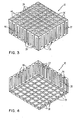
- Heat sink 12 has a plurality of upstanding cooling fin elements 20 that are hollow. Each fin has four upstanding leg portions 22 that are joined at the top of the fin 20. The leg portions 22 are capable of flexing to accommodate for expansion and contraction of the surface that the heat sink 12 is bonded to, as will be explained and illustrated in more detail.
- the leg portions 22 are preferably formed by the intersection of two slots 26 and 28.
- a hole 24 is provided in the top portion of each cooling fin when impingement cooling, in the combination in Fig. 1, is used for dissipating heat.
- the hole 24 extends downwardly to at least the slots 26 and 28 providing a passage through the fin with openings in the lower portion to allow cooling medium to flow downwardly and outwardly. This flow of fluid, normally air, provides effective heat dissipation. Turbulence is caused by air flowing outwardly about the four leg portions 22 after entering top opening 24, which dispels the boundary air layer that normally would impede heat transfer.
- heat sink 12 has a plurality of square flat base portions 30 which, in use, are bonded to the body to be cooled.
- the portions 30 are square, but could be rectangular or round as well.
- the base portions 30 are attached to the cooling elements 20 but in a very special manner.
- the leg portions 22 of the cooling fin elements 20 are each attached to a different but adjacent base portion 30.
- Each base portion 30 is thus attached to four different fin elements.
- the adjacent corners of four base portions 30 thus support a single fin element.
- any relative movement of the individual base portions 30, due to heating or cooling effects, is absorbed by flexing of the leg portions 22 of the fin elements.
- the heat sink structure is unitary because the base portions 30 are all tied together by the upper portions of the cooling fins 20.
- base portions 30 provide effective thermal transfer of heat to the heat fins 20. Furthermore, a hot spot, caused as for example by an active semiconductor device, beneath a base portion 30 results in transfer of heat to four separate heat fins which reduces thermal resistance and also promote a more uniform temperature profile in the heat generating body.
- the base portions 30 that support the fin elements along the edges of the heat sink 12 are approximately one-half the size of the centrally located base portions 30. This is necessary because the outside row of base portions are required to secure the leg portions of only two fin elements.
- the heat sink can be made of any suitable material having a thermal conductivity sufficient to meet the demands of the particular application. However, metals are preferred. Preferred metals are copper and aluminium.
- the heat sink can be bonded to the heat generating body by any suitable technique, as for example, by brazing or soldering.
- the support element i.e. the lid of a semiconductor package
- the unitary heat sink of the invention can be fabricated by the method which will now be described. It will be apparent that the relatively complex and intricate heat sink structure can be fabricated by performing a number of simple routine machining operations.
- a solid rectangular or square block of material having the desired size is selected.
- a first plurality of parallel spaced slots 26, as most clearly shown in Fig. 4 is machined in the bottom of the selected block. The depth of the slots is obviously less than the thickness of the block itself.
- a second plurality of parallel spaced slots 28 that are transverse to slots 26 is subsequently machined in the bottom of the block. This forms the surface configurations of base portions 30 that serves as the bonding interface.
- a third plurality of slots 44, positioned between slots 26 which overlap in the block, are machined in the top opposite side of the block.
- a fourth plurality of parallel slots 46 are machined from the top of the block which are positioned between slots 28 and are also in overlapping relation. These slots 44 and 46 form the exterior shape of the cooling fin elements 20. Holes 24 are drilled from the top of the block to open the fins for impingement cooling.
- slots 44 and 46 from the top of the block shape the exterior surface of the fins 20.
- Slots 26 and 28 from the bottom of the block form the base portions 30 of the fins and also shape the leg portions 22.
- the heat sink of the invention can be fabricated in any other suitable manner, as for example by casting. If the heat sink is cast, the slots 26, 28, 44 and 46 can be slightly tapered to facilitate removal of the heat sink 12 from the mold.
- the depth of the slots and the height of the cooling fin elements can be varied to meet the requirements of the specific application.
- the width of slots 26 and 28 constitutes approximately 1/3 to 1/2 of the total width of the fin elements 20.
- the relative dimensions of the slots 26 and 28 to the overall height of the cooling fin elements 20 determines the cooling effectiveness and capacity of the structure.
- the ratio of the height of the cooling element 20 to the width of slots 26 or 28 is the range of 5 to 50.
Landscapes
- Engineering & Computer Science (AREA)
- Physics & Mathematics (AREA)
- Thermal Sciences (AREA)
- Mechanical Engineering (AREA)
- General Engineering & Computer Science (AREA)
- Cooling Or The Like Of Semiconductors Or Solid State Devices (AREA)
Applications Claiming Priority (2)
| Application Number | Priority Date | Filing Date | Title |
|---|---|---|---|
| US48987583A | 1983-04-29 | 1983-04-29 | |
| US489875 | 1983-04-29 |
Publications (3)
| Publication Number | Publication Date |
|---|---|
| EP0123795A2 true EP0123795A2 (de) | 1984-11-07 |
| EP0123795A3 EP0123795A3 (en) | 1986-12-10 |
| EP0123795B1 EP0123795B1 (de) | 1990-05-02 |
Family
ID=23945634
Family Applications (1)
| Application Number | Title | Priority Date | Filing Date |
|---|---|---|---|
| EP84101103A Expired - Lifetime EP0123795B1 (de) | 1983-04-29 | 1984-02-03 | Einteilige Wärmesenke für einen elektronischen Anordnungsmodul |
Country Status (4)
| Country | Link |
|---|---|
| EP (1) | EP0123795B1 (de) |
| JP (1) | JPS59202657A (de) |
| CA (1) | CA1204523A (de) |
| DE (1) | DE3482156D1 (de) |
Cited By (5)
| Publication number | Priority date | Publication date | Assignee | Title |
|---|---|---|---|---|
| DE4314663A1 (de) * | 1993-05-04 | 1994-11-10 | Alusuisse Lonza Services Ag | Kühlkörper für Halbleiterbauelemente |
| EP0696160A2 (de) | 1994-08-02 | 1996-02-07 | Hoogovens Aluminium Profiltechnik GmbH | Kühlvorrichtung für elektrische bzw. elektronische Bauelemente mit einer Grundplatte und mit Kühlelementen sowie Verfahren zu deren Herstellung |
| EP2311085A4 (de) * | 2008-06-30 | 2014-09-10 | Alcatel Lucent Usa Inc | Monolithische kühlkörperentwürfe mit komplexer struktur |
| CN108321135A (zh) * | 2018-01-24 | 2018-07-24 | 西安交通大学 | 一种组合式柱状的芯片强化沸腾换热微结构及其制造方法 |
| CN116074994A (zh) * | 2021-10-29 | 2023-05-05 | 上海微电子装备(集团)股份有限公司 | 一种隔热结构及光配向设备 |
Families Citing this family (6)
| Publication number | Priority date | Publication date | Assignee | Title |
|---|---|---|---|---|
| US4765397A (en) * | 1986-11-28 | 1988-08-23 | International Business Machines Corp. | Immersion cooled circuit module with improved fins |
| GB2204181B (en) * | 1987-04-27 | 1990-03-21 | Thermalloy Inc | Heat sink apparatus and method of manufacture |
| JPH088421B2 (ja) * | 1991-03-20 | 1996-01-29 | さとみ 伊藤 | 放熱装置 |
| GB2276763B (en) * | 1993-03-30 | 1997-05-07 | Thermalloy Inc | Method and apparatus for dissipating thermal energy |
| JPH07321265A (ja) * | 1994-05-27 | 1995-12-08 | Fujitsu Ltd | 集積回路素子モジュールの冷却構造 |
| US5791406A (en) * | 1994-08-02 | 1998-08-11 | Hoogovens Aluminium Profiltechnik, Gmbh | Cooling device for electrical or electronic components having a base plate and cooling elements and method for manufacturing the same |
Family Cites Families (1)
| Publication number | Priority date | Publication date | Assignee | Title |
|---|---|---|---|---|
| US4296455A (en) * | 1979-11-23 | 1981-10-20 | International Business Machines Corporation | Slotted heat sinks for high powered air cooled modules |
-
1983
- 1983-11-30 JP JP58224556A patent/JPS59202657A/ja active Pending
-
1984
- 1984-02-03 EP EP84101103A patent/EP0123795B1/de not_active Expired - Lifetime
- 1984-02-03 DE DE8484101103T patent/DE3482156D1/de not_active Expired - Lifetime
- 1984-03-20 CA CA000449988A patent/CA1204523A/en not_active Expired
Cited By (5)
| Publication number | Priority date | Publication date | Assignee | Title |
|---|---|---|---|---|
| DE4314663A1 (de) * | 1993-05-04 | 1994-11-10 | Alusuisse Lonza Services Ag | Kühlkörper für Halbleiterbauelemente |
| EP0696160A2 (de) | 1994-08-02 | 1996-02-07 | Hoogovens Aluminium Profiltechnik GmbH | Kühlvorrichtung für elektrische bzw. elektronische Bauelemente mit einer Grundplatte und mit Kühlelementen sowie Verfahren zu deren Herstellung |
| EP2311085A4 (de) * | 2008-06-30 | 2014-09-10 | Alcatel Lucent Usa Inc | Monolithische kühlkörperentwürfe mit komplexer struktur |
| CN108321135A (zh) * | 2018-01-24 | 2018-07-24 | 西安交通大学 | 一种组合式柱状的芯片强化沸腾换热微结构及其制造方法 |
| CN116074994A (zh) * | 2021-10-29 | 2023-05-05 | 上海微电子装备(集团)股份有限公司 | 一种隔热结构及光配向设备 |
Also Published As
| Publication number | Publication date |
|---|---|
| EP0123795A3 (en) | 1986-12-10 |
| JPS59202657A (ja) | 1984-11-16 |
| DE3482156D1 (de) | 1990-06-07 |
| EP0123795B1 (de) | 1990-05-02 |
| CA1204523A (en) | 1986-05-13 |
Similar Documents
| Publication | Publication Date | Title |
|---|---|---|
| US4620216A (en) | Unitary slotted heat sink for semiconductor packages | |
| EP0127115B1 (de) | Wärmesenkstruktur für eine elektronische Packung | |
| KR100523498B1 (ko) | 고전력 마이크로프로세서를 냉각시키기 위한평행-판/핀-휜 하이브리드 구리 방열 장치 | |
| US5567986A (en) | Heat sink | |
| US4442450A (en) | Cooling element for solder bonded semiconductor devices | |
| US6263959B1 (en) | Plate type heat pipe and cooling structure using it | |
| US4009752A (en) | Warp-resistant heat sink | |
| US4860165A (en) | Semiconductor chip carrier package | |
| JP2981586B2 (ja) | ヒートシンク | |
| US5168348A (en) | Impingment cooled compliant heat sink | |
| US5489752A (en) | Process for dissipating heat from a semiconductor package | |
| US5097385A (en) | Super-position cooling | |
| EP0123795B1 (de) | Einteilige Wärmesenke für einen elektronischen Anordnungsmodul | |
| KR102754126B1 (ko) | 플립 칩 볼 그리드 어레이, 그리고 플립 칩 볼 그리드 어레이를 제조하기 위한 방법 | |
| KR930015998A (ko) | 고전력 전자 소자에 의해 발생된 열의 소산성이 개선된 회로 팩 | |
| JPH0157502B2 (de) | ||
| KR100232810B1 (ko) | 절첩식 권선 와이어 열전도 부재를 갖춘 흡열 구조물 | |
| US5025307A (en) | Modular semiconductor device | |
| JP2006287080A (ja) | メモリモジュール | |
| US5206713A (en) | Mounting silicon chips | |
| JPH08222668A (ja) | Icパッケージ | |
| US4972043A (en) | Multi-lead hermetic power package with high packing density | |
| JPS6219074B2 (de) | ||
| JPH06181395A (ja) | 放熱形プリント配線板 | |
| JP2002343909A (ja) | パワーモジュール |
Legal Events
| Date | Code | Title | Description |
|---|---|---|---|
| PUAI | Public reference made under article 153(3) epc to a published international application that has entered the european phase |
Free format text: ORIGINAL CODE: 0009012 |
|
| AK | Designated contracting states |
Designated state(s): DE FR GB IT |
|
| 17P | Request for examination filed |
Effective date: 19841123 |
|
| PUAL | Search report despatched |
Free format text: ORIGINAL CODE: 0009013 |
|
| AK | Designated contracting states |
Kind code of ref document: A3 Designated state(s): DE FR GB IT |
|
| 17Q | First examination report despatched |
Effective date: 19880119 |
|
| GRAA | (expected) grant |
Free format text: ORIGINAL CODE: 0009210 |
|
| AK | Designated contracting states |
Kind code of ref document: B1 Designated state(s): DE FR GB IT |
|
| REF | Corresponds to: |
Ref document number: 3482156 Country of ref document: DE Date of ref document: 19900607 |
|
| ET | Fr: translation filed | ||
| ITF | It: translation for a ep patent filed | ||
| ITTA | It: last paid annual fee | ||
| PLBE | No opposition filed within time limit |
Free format text: ORIGINAL CODE: 0009261 |
|
| STAA | Information on the status of an ep patent application or granted ep patent |
Free format text: STATUS: NO OPPOSITION FILED WITHIN TIME LIMIT |
|
| 26N | No opposition filed | ||
| PGFP | Annual fee paid to national office [announced via postgrant information from national office to epo] |
Ref country code: GB Payment date: 19940118 Year of fee payment: 11 |
|
| PGFP | Annual fee paid to national office [announced via postgrant information from national office to epo] |
Ref country code: FR Payment date: 19940126 Year of fee payment: 11 |
|
| PGFP | Annual fee paid to national office [announced via postgrant information from national office to epo] |
Ref country code: DE Payment date: 19940225 Year of fee payment: 11 |
|
| PG25 | Lapsed in a contracting state [announced via postgrant information from national office to epo] |
Ref country code: GB Effective date: 19950203 |
|
| GBPC | Gb: european patent ceased through non-payment of renewal fee |
Effective date: 19950203 |
|
| PG25 | Lapsed in a contracting state [announced via postgrant information from national office to epo] |
Ref country code: FR Effective date: 19951031 |
|
| PG25 | Lapsed in a contracting state [announced via postgrant information from national office to epo] |
Ref country code: DE Effective date: 19951101 |
|
| REG | Reference to a national code |
Ref country code: FR Ref legal event code: ST |