EP0123821A2 - Appareil pour couper des pièces de travail d'un cordon brut - Google Patents
Appareil pour couper des pièces de travail d'un cordon brut Download PDFInfo
- Publication number
- EP0123821A2 EP0123821A2 EP84102111A EP84102111A EP0123821A2 EP 0123821 A2 EP0123821 A2 EP 0123821A2 EP 84102111 A EP84102111 A EP 84102111A EP 84102111 A EP84102111 A EP 84102111A EP 0123821 A2 EP0123821 A2 EP 0123821A2
- Authority
- EP
- European Patent Office
- Prior art keywords
- receiving element
- receiving
- feed direction
- split pieces
- feed
- Prior art date
- Legal status (The legal status is an assumption and is not a legal conclusion. Google has not performed a legal analysis and makes no representation as to the accuracy of the status listed.)
- Granted
Links
Images


Classifications
-
- B—PERFORMING OPERATIONS; TRANSPORTING
- B23—MACHINE TOOLS; METAL-WORKING NOT OTHERWISE PROVIDED FOR
- B23D—PLANING; SLOTTING; SHEARING; BROACHING; SAWING; FILING; SCRAPING; LIKE OPERATIONS FOR WORKING METAL BY REMOVING MATERIAL, NOT OTHERWISE PROVIDED FOR
- B23D15/00—Shearing machines or shearing devices cutting by blades which move parallel to themselves
- B23D15/005—Shearing machines or shearing devices cutting by blades which move parallel to themselves for bias cutting of webs or sheets
-
- B—PERFORMING OPERATIONS; TRANSPORTING
- B23—MACHINE TOOLS; METAL-WORKING NOT OTHERWISE PROVIDED FOR
- B23D—PLANING; SLOTTING; SHEARING; BROACHING; SAWING; FILING; SCRAPING; LIKE OPERATIONS FOR WORKING METAL BY REMOVING MATERIAL, NOT OTHERWISE PROVIDED FOR
- B23D15/00—Shearing machines or shearing devices cutting by blades which move parallel to themselves
- B23D15/06—Sheet shears
-
- B—PERFORMING OPERATIONS; TRANSPORTING
- B23—MACHINE TOOLS; METAL-WORKING NOT OTHERWISE PROVIDED FOR
- B23D—PLANING; SLOTTING; SHEARING; BROACHING; SAWING; FILING; SCRAPING; LIKE OPERATIONS FOR WORKING METAL BY REMOVING MATERIAL, NOT OTHERWISE PROVIDED FOR
- B23D23/00—Machines or devices for shearing or cutting profiled stock
- B23D23/02—Machines or devices for shearing or cutting profiled stock otherwise than in a plane perpendicular to the axis of the stock
Definitions
- the invention relates to a device for producing split pieces from a heated raw material strand which is cyclically advanced to a splitting device, which has a base body with a lower knife aligned obliquely to the material strand and an upper knife fastened to a vertically movable cutting punch, and to which one receives and splits the split pieces a transport device feeding the forming device connects, the feed direction of the strand of material and the feed direction to the forming device being in an unchangeable relation.
- Such a device is mentioned for example in AT-B-351.337.
- a method for producing heated split pieces is described, wherein a uniform heating of the rod-shaped starting material and a continuous workflow are achieved by welding flat material rods to form a flat material strand.
- the strand which has been heated to the forging temperature, then enters the splitting device, in which the knives arranged at an angle to the direction of advance separate the splitting pieces roughly corresponding to the outline shapes of the products to be produced, which then to the drop forge.
- the heating of the strand takes place essentially parallel to the gap direction, that is to say sections extending obliquely to the strand.
- the invention has now set itself the task of creating a device in which despite changing the Thomasli nienlage the workflow is not disturbed as far as possible, and the adaptation to the changed conditions can be achieved in a simple manner.
- the two knives of the splitting device are arranged such that they can be rotated at an angle to the feed direction, and the transport device is dependent on it from the angular adjustment of the knives rotatable receiving element for the split pieces, which rotates each of the split pieces in a congruent feed position to the forming device.
- the adjustment of the angle of the two knives to the feed direction opens up a number of previously unavailable options.
- the deviation from the feed direction caused by the uneven elongations of a flat material strand is compensated for by the fact that the angle of the splitting device to the material strand is returned to the original amount despite its change in position.
- angle-adjustable knives Another advantage of the angle-adjustable knives is that, in order to produce longer or shorter split pieces, the angle to the feed direction can also be changed until the desired size of the split pieces can be separated from the sheet of flat material. If different sizes can be produced with known devices that coldly separate the split pieces (AT-B-361 759), the feed path of the material bars is changed, so that a much larger space is required. The A Of course, problems mentioned above do not arise from the outset with these facilities.
- Another significant advantage of the device according to the invention results from the possibility of producing split pieces whose cutting lines are not parallel.
- the rotatability of the knives allows flat material strands to be broken down into triangular and trapezoidal split pieces by rotating the knives after each cut. The split pieces therefore turn out rotated by 180 G alternately.
- Trapezoidal split pieces can be used, for example, to manufacture plowshares.
- the cut-off split pieces are rotated into the position that they require for processing in the subsequent forming machine, in particular a drop forge.
- the distance between the heating zone and the blades of the splitting device; of which the lower knife is preferably cooled, should be small in order to keep the temperature loss as small as possible.
- the arrangement of individually rotatable knives in the splitting device which of course must be rotated by the same amount, requires a relatively large width of the splitting device. It is therefore much more advantageous if the entire splitting device can be rotated about a vertical axis which runs through the longitudinal axis of the strand of material. After this version, its width remains at a minimum measure limited, which is composed of the length of the longest gap piece to be produced plus the bilateral guide area for the cutting punch.
- the splitting device is therefore arranged, for example, on a rotary table which has circular slots which are fastened behind by fastening elements.
- the type of attachment can be chosen to suit the circumstances, and various possibilities are also conceivable for the rotary movement of the entire splitting device: it can be done, for example, hydraulically or by means of a motor, if necessary also manually.
- the angle of rotation is preferably between 45 ° and 150 °.
- this is preferably rotatably mounted on a support arm about a vertical axis, the support arm being horizontally movable between the receiving position of the receiving element and a transfer position, in which each Splitting piece is located in the receiving element in the feed position to the forming device.
- the support arm itself can be pivoted about a vertical axis perpendicular to the feed direction of the split pieces for the shaping device, preferably by means of hydraulic devices between the receiving position and the transfer position.
- its horizontal displacement would also be conceivable.
- a preferred embodiment of the device according to the invention provides that the rotatable receiving element is held in the transfer position by spring loading in a central position in which it is aligned with a transport part extending in the feed direction to the forming device.
- the receiving element which automatically returns to the transfer position in this way, is brought into the receiving position by contacting the stops of the splitting device that change with the rotation of the knives, for example by pivoting the support arm, it can change from the neutral central position depending on the extent of the angle adjustment turn under tension of a return spring, which moves it back to the central position during the return to the transfer position. It is of course irrelevant whether the receiving element rotates to the left or to the right when it takes up the receiving position by contacting the splitting device. The receiving element will then also be in the neutral central position in the receiving position when a frequently given cutting angle of the knives is set. In any case, the longitudinal extent of the receiving element extends in the receiving position at an angle to the direction of advance.
- the receiving element is held in the receiving position in a central position in which it is fed direction is aligned, and between the recording and the transfer of each slit can be rotated alternately to the left or right, the two end positions differing by 180 °.
- the split pieces After transfer of the split pieces to the transport part extending to the forming device, the split pieces are therefore arranged in an orderly congruent arrangement, although they enter the receiving element in a position offset by 180 ° in each case.
- the receiving element can be rotated by 180 ° between the receiving and the transfer of every second split piece. This means that one split piece in each case is transported to the forming device in the cut-off position, and every second split piece which is rotated by 180 ° is turned into the corresponding position during the transfer into the subsequent transport part.
- the divided slit pieces When they are fed to the forming device, the divided slit pieces should cover the shortest possible feed path, in which the proportion of uncontrollable distances within which they are moved, for example by gravity, is as small as possible.
- a receiving drawer is formed as the receiving element, and the lower knife of the splitting device has a recess on the cutting edge side, into which the receiving drawer of the transport device is pushed horizontally in the receiving position.
- the transport device has a feed trough extending in the feed direction, the receiving drawer being aligned with the feed trough in the transfer position.
- a gripping pliers is used as the receiving element, which transfers the split pieces to a conveyor belt in the congruent position, which causes further travel.
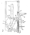
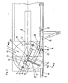
- the device according to the invention has a splitting device which is arranged on a rotary table 9 so as to be rotatable about the axis 24.
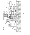
- the splitting device 1 consists of a base body 7, on which a lower knife 5 is fixed, and a cutting punch 2, which is movable vertically on guide columns 13 arranged in the base body 7, on which an upper knife 4 is attached.
- the movement of the cutting punch 2 takes place by means of a hydraulic device (not described in more detail) as a function of the horizontal, intermittent feed of a flat material strand 6 in the feed direction A.
- the axis 24 runs through the longitudinal axis of the flat material strand 6.
- a journal 29 serves as the axle bearing of the base body 7, which is inserted in the rotary table 9.
- circular-arc slots 10 are recessed, which are engaged by guide elements 12 which are inserted into the base body 7.
- guide elements 12 can be formed by machine screws with nuts, but preferably fasteners that can be released and fixed quickly can also be provided, for example hydraulic tensioning devices.
- a drive for the rotation of the splitting device 1 consists, for example, of a gear part 30 of a motor (not shown) (FIG. 5, 6) inserted into a spur toothing 29 of the base body 7, but it can also be done hydraulically.
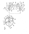
- the lower knife 5 is inserted into a laterally open recess 8 of the base body 7, and itself also has a recess 25 on the side of the cutting edge 26 (FIG. 4).
- the cutting edges 26 of the two knives 4, 5 are curved in order to separate split pieces 23 from the material strand 6, which roughly correspond to the outline shape of the products to be produced therefrom.
- Such products include wrenches and other tools.
- the knives 4, 5 of the splitting device 1 and thus their central plane running through the guide columns 13 are aligned at an angle to the feed direction A, which can be, for example, 25 ° for the production of wrenches. In this case, this angle is dependent on the width of the strand of material 6 to be processed and the length of the gap pieces 23 to be produced, which must additionally have gripping projections at both ends.
- This enables the strand to be heated much more uniformly than when the individual split pieces are heated.
- the heating takes place in inclined zones running approximately parallel to the splitting device 1, so that the end of the strand to be cut is heated uniformly over the width.
- the heating, different material properties and widths as well as thicknesses of the individual welded rods can lead to a curvature of the material strand 6 in its plane, so that a lateral deviation from the pushing direction A occurs. This changes the cutting angle to the feed direction A and thus also the position of the cutting line of the unchanged splitting device 1.
- the curved cutting edges now cause a change in the spacing of the cutting lines from one another when the material strand 6 laterally deflects, so that in the areas of small spacing, in particular in the transition areas to the absolutely necessary gripping lugs, a tapering which enables their breaking off or, in extreme cases, their complete separation can take place. If such a lateral deviation of the material strand 6, which leads to an undesired change in shape of the split pieces 23, is now found, the split device 1 is rotated by a certain angular amount, so that the originally selected angle to the feed direction A is restored in this way at all times .
- the rotation of the splitting device 1 also enables the inclination to be easily adjusted when the knives 4, 5 are changed, for example to produce splitting pieces 23 for longer or shorter wrenches, possibly in connection with a change in the feed length per work cycle.
- a transport device 14 is connected to the splitting device 1, which picks up the cut splitting pieces 23 and conveys them to the forming device, in particular to a drop forge in the feed direction B, which is approximately parallel to the feed direction A.
- the transport device 14 consists, on the one hand, of a receiving element 17 arranged on a support arm 15 and, on the other hand, of a further transport part 3.
- the receiving element 17 is in particular by a receiving drawer and the further transport part 3 by a feed trough 18 formed, which is coated by a pressure medium operated slide 20.
- the support arm 15 is angled several times and is pivotally mounted at the other end about a vertical axis 22 by means of a hydraulic device 16 (FIGS. 1-3).
- the receiving element 17 in the transfer position shown in FIGS. 1 and 2 closes a gap between the two parts of the further transport part 3, a strip-shaped stop 19 being provided as a limitation. From this transfer position, the receiving element 17 can be pivoted into the receiving position shown in FIGS. 3 and 4, in which it is partly inserted into the already mentioned recess 25 of the lower knife 5. A separated gap piece 23 therefore falls into the receiving element 17, which then 1, 2 is moved, and is fed from there by the slide 20 via the further transport part 3 of the drop forge.
- FIGS. 1-4 of an occasional adjustment of the angle of the splitting device 1 an exact contact of the receiving element 17, especially when it is implemented as a receiving drawer in the recess 25 of the lower knife 5, would no longer exist.
- the receiving element 17 is therefore rotatable on the support arm 15 about a vertical axis 21. so that it can adapt to the change in angle.
- the free, unintentional rotation of the receiving element is prevented by a spring element 27, which holds the receiving element 17 in a neutral central position by acting on both sides, or in the event of a rotation to adapt to the changed angle of the splitting device 1 to the feed direction A again returns the middle position in which it is in alignment with the transport part 3 in the transfer position.
- the angled support arm 15 is guided obliquely downward in a partial area, so that it can move below the slide 20 and its actuating device.
- the support 28 carrying the front part of the slider 20 can, for example, be approximately V-shaped.
- FIGS. 5 and 6 schematically show two further versions of the device according to the invention in plan view, the detailed version of the individual components preferably corresponding to that shown in FIGS. 1-4. While there the rotation of the splitting device 1 only to compensate for changes in position of the material strand 6 or 5 and 6 are suitable for producing triangular or trapezoidal split pieces, that is to say those in which the cut lines do not run parallel. The splitting device 1 must therefore be rotated into a different position after each cut. In each of the two figures, two successive work steps are shown in which split pieces are separated in a non-congruent position and then transferred to the congruent position.
- a split piece 23 was cut off from the heated material strand 6 introduced into the splitting device 1 in the feed direction A, the cutting line running at an angle ⁇ to the feed direction A, while the cut generated in the previous work cycle takes the angle ⁇ to the feed direction A. .
- the receiving element is rotated about the axis 21 on the support arm 15.
- the support arm 15 can be pivoted from the receiving position into the transfer position of the gap piece 23 to the further transport part 3, as also already mentioned.
- the split device 1 (arrow D) is rotated into the second cutting position (angle ⁇ ) during its transfer to the transport part 3, the strand of material 6 is advanced, and then the split piece is separated as soon as the receiving element 17 is again in the receiving position has returned.
- the now separated gap piece 23 is in a position rotated by 180 ° in the receiving element 17, as can be seen from the lower part of the drawing.
- a pivoting takes place in this case, the receiving element 17 by 90 0 in the opposite rotational direction (arrow C ').
- the two end positions of the receiving element 17 differ by 180 °, so that the gap pieces 23 are congruent.
- the transfer of the split pieces into congruent positions is achieved in that each first of the two twist split pieces in the cut position is fed from the transport device 14 in the unchanged position to the forming device, while every second split piece is conveyed to the transfer position during transport ( lower part of the drawing) is rotated by 180 °.
Landscapes
- Engineering & Computer Science (AREA)
- Mechanical Engineering (AREA)
- Forging (AREA)
- Disintegrating Or Milling (AREA)
- Processing Of Solid Wastes (AREA)
- Noodles (AREA)
- Seal Device For Vehicle (AREA)
Applications Claiming Priority (2)
| Application Number | Priority Date | Filing Date | Title |
|---|---|---|---|
| AT798/83 | 1983-03-08 | ||
| AT0079883A AT380416B (de) | 1983-03-08 | 1983-03-08 | Einrichtung zur herstellung von spaltstuecken |
Publications (3)
| Publication Number | Publication Date |
|---|---|
| EP0123821A2 true EP0123821A2 (fr) | 1984-11-07 |
| EP0123821A3 EP0123821A3 (en) | 1986-06-18 |
| EP0123821B1 EP0123821B1 (fr) | 1988-10-19 |
Family
ID=3499981
Family Applications (1)
| Application Number | Title | Priority Date | Filing Date |
|---|---|---|---|
| EP84102111A Expired EP0123821B1 (fr) | 1983-03-08 | 1984-02-29 | Appareil pour couper des pièces de travail d'un cordon brut |
Country Status (3)
| Country | Link |
|---|---|
| EP (1) | EP0123821B1 (fr) |
| AT (2) | AT380416B (fr) |
| DE (1) | DE3474641D1 (fr) |
Cited By (2)
| Publication number | Priority date | Publication date | Assignee | Title |
|---|---|---|---|---|
| FR2573687A1 (fr) * | 1984-11-27 | 1986-05-30 | Daimler Benz Ag | Dispositif de cisaillage en biais de l'extremite d'un tube |
| FR2636872A1 (fr) * | 1988-09-28 | 1990-03-30 | Peddinghaus Rolf | Installation pour tronconner des sections de barres d'acier a partir d'une barre d'acier |
Families Citing this family (1)
| Publication number | Priority date | Publication date | Assignee | Title |
|---|---|---|---|---|
| JP7230034B2 (ja) * | 2018-01-30 | 2023-02-28 | ヒューレット-パッカード デベロップメント カンパニー エル.ピー. | 媒体切断構成および方法 |
Family Cites Families (6)
| Publication number | Priority date | Publication date | Assignee | Title |
|---|---|---|---|---|
| US2767789A (en) * | 1954-06-01 | 1956-10-23 | Littell Machine Co F J | Oscillating shear for cutting trapezoidal shapes |
| US3122042A (en) * | 1961-01-13 | 1964-02-25 | Littell Machine Co F J | Oscillating die and punch press combination |
| US3440910A (en) * | 1967-03-23 | 1969-04-29 | Harry E Scribner | Universal shear |
| US4022088A (en) * | 1976-03-18 | 1977-05-10 | Lothar Stotzel | Process and apparatus for the cutting of transformer core sheets |
| DE2752912C2 (de) * | 1977-11-26 | 1985-06-27 | C. Behrens Ag, 3220 Alfeld | Schneidpresse zur Bearbeitung plattenförmiger Werkstücke aus Blech od. dgl. |
| AT351337B (de) * | 1978-03-24 | 1979-07-25 | Franz Kroesbacher Kommanditges | Verfahren zur herstellung von erwaermten spaltstuecken fuer gesenkschmieden |
-
1983
- 1983-03-08 AT AT0079883A patent/AT380416B/de not_active IP Right Cessation
-
1984
- 1984-02-29 DE DE8484102111T patent/DE3474641D1/de not_active Expired
- 1984-02-29 EP EP84102111A patent/EP0123821B1/fr not_active Expired
- 1984-02-29 AT AT84102111T patent/ATE38003T1/de not_active IP Right Cessation
Cited By (2)
| Publication number | Priority date | Publication date | Assignee | Title |
|---|---|---|---|---|
| FR2573687A1 (fr) * | 1984-11-27 | 1986-05-30 | Daimler Benz Ag | Dispositif de cisaillage en biais de l'extremite d'un tube |
| FR2636872A1 (fr) * | 1988-09-28 | 1990-03-30 | Peddinghaus Rolf | Installation pour tronconner des sections de barres d'acier a partir d'une barre d'acier |
Also Published As
| Publication number | Publication date |
|---|---|
| DE3474641D1 (en) | 1988-11-24 |
| ATA79883A (de) | 1985-10-15 |
| EP0123821A3 (en) | 1986-06-18 |
| EP0123821B1 (fr) | 1988-10-19 |
| ATE38003T1 (de) | 1988-11-15 |
| AT380416B (de) | 1986-05-26 |
Similar Documents
| Publication | Publication Date | Title |
|---|---|---|
| EP0721385B1 (fr) | Installation de production continue d'elements de construction | |
| DE2334072A1 (de) | Verfahren und vorrichtung zum zuschneiden von bogenmaterial | |
| DE2347281A1 (de) | Verfahren und vorrichtung zum zerteilen von tiefgefrorenen platten von lebensmitteln in einzelportionen | |
| DE2254262C2 (de) | Vorrichtung zum Anbringen von Beschlägen auf Werkstücken | |
| DE3217038A1 (de) | Verfahren und vorrichtung zum stanzschneiden von bahn- oder plattenfoermigem schneidgut | |
| DE2208642A1 (de) | Verfahren und maschine zum zerschneiden von fleischscheiben | |
| DE1502997A1 (de) | Blechschere zum Besaeumen und Schneiden der Randstreifen | |
| EP1351783A1 (fr) | Dispositif de coupe transversale de bandes metalliques | |
| DE3312746C2 (fr) | ||
| EP0123821B1 (fr) | Appareil pour couper des pièces de travail d'un cordon brut | |
| DE3300999C2 (de) | Vorrichtung zum Zuschneiden von Bogenmaterial | |
| DE2129139C2 (de) | Verfahren und Vorrichtung zum Herstellen von Reißverschlüssen mit kuppelgliederfreien Bereichen | |
| DE3442466C2 (fr) | ||
| DE69422626T2 (de) | Zuführvorrichtung für schneidvorrichtung | |
| DE115964C (fr) | ||
| DE3536949C2 (fr) | ||
| DE2553586A1 (de) | Verfahren zum bearbeiten von fischskeletten | |
| DE2523203A1 (de) | Stanzgeraet zur herstellung spitzgezahnter stosskanten an furnierstreifen o.dgl. | |
| DE3734836C2 (fr) | ||
| DE1752934C3 (de) | Verfahren zur Herstellung von Heizkörperplatten | |
| DE1611016C (de) | Verfahren zum kontinuierlichen Herstellen von beschnittenen Druckerzeugnisblöcken und Vorrichtung zur Durchführung dieses Verfahrens | |
| DE2621836A1 (de) | Vorrichtung zur weiterverarbeitung eines knaeckebrotbandes beliebiger laenge | |
| DE694251C (de) | Vorrichtung zur Herstellung von Sammelbuechern, degereiht sind | |
| DE182815C (fr) | ||
| DE180340C (fr) |
Legal Events
| Date | Code | Title | Description |
|---|---|---|---|
| PUAI | Public reference made under article 153(3) epc to a published international application that has entered the european phase |
Free format text: ORIGINAL CODE: 0009012 |
|
| AK | Designated contracting states |
Designated state(s): AT DE FR GB IT SE |
|
| RAP1 | Party data changed (applicant data changed or rights of an application transferred) |
Owner name: EUMUCO AKTIENGESELSCHAFT FUER MASCHINENBAU |
|
| RAP1 | Party data changed (applicant data changed or rights of an application transferred) |
Owner name: EUMUCO AKTIENGESELSCHAFT FUER MASCHINENBAU |
|
| PUAL | Search report despatched |
Free format text: ORIGINAL CODE: 0009013 |
|
| AK | Designated contracting states |
Kind code of ref document: A3 Designated state(s): AT DE FR GB IT SE |
|
| 17P | Request for examination filed |
Effective date: 19860711 |
|
| 17Q | First examination report despatched |
Effective date: 19871014 |
|
| ITF | It: translation for a ep patent filed | ||
| GRAA | (expected) grant |
Free format text: ORIGINAL CODE: 0009210 |
|
| AK | Designated contracting states |
Kind code of ref document: B1 Designated state(s): AT DE FR GB IT SE |
|
| REF | Corresponds to: |
Ref document number: 38003 Country of ref document: AT Date of ref document: 19881115 Kind code of ref document: T |
|
| REF | Corresponds to: |
Ref document number: 3474641 Country of ref document: DE Date of ref document: 19881124 |
|
| ET | Fr: translation filed | ||
| GBT | Gb: translation of ep patent filed (gb section 77(6)(a)/1977) | ||
| PLBE | No opposition filed within time limit |
Free format text: ORIGINAL CODE: 0009261 |
|
| STAA | Information on the status of an ep patent application or granted ep patent |
Free format text: STATUS: NO OPPOSITION FILED WITHIN TIME LIMIT |
|
| 26N | No opposition filed | ||
| ITTA | It: last paid annual fee | ||
| PGFP | Annual fee paid to national office [announced via postgrant information from national office to epo] |
Ref country code: GB Payment date: 19930105 Year of fee payment: 10 |
|
| PGFP | Annual fee paid to national office [announced via postgrant information from national office to epo] |
Ref country code: FR Payment date: 19930120 Year of fee payment: 10 |
|
| PGFP | Annual fee paid to national office [announced via postgrant information from national office to epo] |
Ref country code: SE Payment date: 19930125 Year of fee payment: 10 |
|
| PGFP | Annual fee paid to national office [announced via postgrant information from national office to epo] |
Ref country code: AT Payment date: 19930225 Year of fee payment: 10 |
|
| PGFP | Annual fee paid to national office [announced via postgrant information from national office to epo] |
Ref country code: DE Payment date: 19930308 Year of fee payment: 10 |
|
| PG25 | Lapsed in a contracting state [announced via postgrant information from national office to epo] |
Ref country code: GB Effective date: 19940228 Ref country code: AT Effective date: 19940228 |
|
| PG25 | Lapsed in a contracting state [announced via postgrant information from national office to epo] |
Ref country code: SE Free format text: LAPSE BECAUSE OF NON-PAYMENT OF DUE FEES Effective date: 19940301 |
|
| GBPC | Gb: european patent ceased through non-payment of renewal fee |
Effective date: 19940228 |
|
| PG25 | Lapsed in a contracting state [announced via postgrant information from national office to epo] |
Ref country code: FR Effective date: 19941031 |
|
| PG25 | Lapsed in a contracting state [announced via postgrant information from national office to epo] |
Ref country code: DE Effective date: 19941101 |
|
| REG | Reference to a national code |
Ref country code: FR Ref legal event code: ST |
|
| EUG | Se: european patent has lapsed |
Ref document number: 84102111.6 Effective date: 19941010 |