EP0123898A2 - Orgue-accordéon électronique - Google Patents
Orgue-accordéon électronique Download PDFInfo
- Publication number
- EP0123898A2 EP0123898A2 EP84103349A EP84103349A EP0123898A2 EP 0123898 A2 EP0123898 A2 EP 0123898A2 EP 84103349 A EP84103349 A EP 84103349A EP 84103349 A EP84103349 A EP 84103349A EP 0123898 A2 EP0123898 A2 EP 0123898A2
- Authority
- EP
- European Patent Office
- Prior art keywords
- accordion
- pressure sensor
- bellows
- oscillators
- switches
- Prior art date
- Legal status (The legal status is an assumption and is not a legal conclusion. Google has not performed a legal analysis and makes no representation as to the accuracy of the status listed.)
- Withdrawn
Links
Images
Classifications
-
- G—PHYSICS
- G10—MUSICAL INSTRUMENTS; ACOUSTICS
- G10H—ELECTROPHONIC MUSICAL INSTRUMENTS; INSTRUMENTS IN WHICH THE TONES ARE GENERATED BY ELECTROMECHANICAL MEANS OR ELECTRONIC GENERATORS, OR IN WHICH THE TONES ARE SYNTHESISED FROM A DATA STORE
- G10H1/00—Details of electrophonic musical instruments
- G10H1/32—Constructional details
- G10H1/34—Switch arrangements, e.g. keyboards or mechanical switches specially adapted for electrophonic musical instruments
-
- G—PHYSICS
- G10—MUSICAL INSTRUMENTS; ACOUSTICS
- G10H—ELECTROPHONIC MUSICAL INSTRUMENTS; INSTRUMENTS IN WHICH THE TONES ARE GENERATED BY ELECTROMECHANICAL MEANS OR ELECTRONIC GENERATORS, OR IN WHICH THE TONES ARE SYNTHESISED FROM A DATA STORE
- G10H2230/00—General physical, ergonomic or hardware implementation of electrophonic musical tools or instruments, e.g. shape or architecture
- G10H2230/045—Special instrument [spint], i.e. mimicking the ergonomy, shape, sound or other characteristic of a specific acoustic musical instrument category
- G10H2230/245—Spint accordion, i.e. mimicking accordions; Electrophonic instruments with one or more typical accordion features, e.g. special accordion keyboards or bellows, electrophonic aspects of mechanical accordions, Midi-like control therefor
Definitions
- the invention relates to an electronic accordion organ with an accordion, the controls (buttons) of which, in addition to the accordion valves, also operate electrical switches, with the switches being able to selectively control oscillators or oscillator groups of a control unit.
- buttons or keys of the accordion serving as operating elements can be used in addition to the tone generation in the accordion itself to generate tones in the manner of an electronic control via an electronic control device.
- a single accordion player can produce further voices in parallel, which he can vary in a variety of ways known per se.
- the volume, timbre, reverb and the like of the additional voices can be set so that the overall impression is that of orchestral accompaniment to the accordion.
- the known accordion organs of the type mentioned above only consisted of electrical switches which were also operated by the buttons or keys of the accordion.
- the actual sound generation in the electronic control unit was carried out in a manner known per se, namely, as is known from conventional electronic organs.
- the keyboard of an electronic organ was thus remotely controlled by the corresponding keyboard or the button board of an accordion.
- the known devices of this type were therefore only suitable for accordions whose operation was identical to that of a conventional electronic organ, i.e. the known devices could only be used for chromatic key or button accordions.
- Diatonic accordion are widely used, at least in certain geographic areas and it can not be assumed in every case from the fact that someone who is a diato - dominated African button accordion, is also able to play a chromatic button or key accordion and vice versa .
- the invention is therefore based on the object of developing an electronic accordion organ of the type mentioned in such a way that it makes the diverse possibilities of electronic generation of accompaniment tones also available for diatonic accordions.
- the accordion is diatonic, that a pressure sensor is connected to a bellows of the accordion and assumes different electrical states, depending on whether the bellows is pulled, pressed or not under load, that each switch at least two oscillators are assigned and that, depending on the electrical state of the pressure sensor, one of the oscillators is switched through to generate sound.
- the invention thus completely achieves the underlying task, because the operating states of the pulled or pressed bellows, which are typical of the diatonic instrument, are converted into an electrically evaluable signal, so that overall the area of application of the electronically generated accompanying music extends to such instruments with relatively simple switching means who are working diatonic.
- the invention also has the essential advantage that complete assemblies can be taken from electronic organs known per se and that only additional switching units are required for the selective actuation of the pair of oscillators or oscillator groups (the latter for the case of chords as accompanying music).
- the pressure sensor is designed as a pressure switch with two contacts and a central position.
- This embodiment has the advantage that a strict distinction between the operating states “pulled bellows” and “pressed bellows” is possible, so that no undefined states occur during breaks when the accordion player does not load the bellows.
- the pressure switch is in its middle position and undefined switching states cannot occur because the pressure sensor swings back and forth between the states “pulled” and pressed "when the bellows is not loaded.
- the pressure switch has a pressure-dependent deflectable membrane which carries a fork-shaped contact element which encloses a contact strip with conductive coverings arranged on both sides and separated from one another.
- This embodiment has the advantage that the pressure sensor or pressure switch required for this special application is of particularly simple construction and permits reliable detection of the three operating states.
- switches are connected to the respectively associated plurality of oscillators via a switchover unit that can be controlled by the pressure sensor.
- This arrangement has the advantage that a logical AND operation and selection is carried out because one of the two oscillators or oscillator groups can then and only be actuated when both the assigned key is pressed and the associated operating state of the bellows is present. This also results in a particularly high level of security against unintentional triggering of an oscillator in transition states between individual buttons or switches or from pulling to pressing the bellows.
- the switchover unit has two electronic transmission links, the transmitter of which can be controlled jointly by the switch and the receiver of which can be selectively controlled by the pressure sensor.
- the Transmission lines are formed by optocouplers, the light-emitting diodes of which can be controlled jointly by the switches and whose phototransistors or photoresistors can be selectively controlled by the contacts of the pressure switch serving as a pressure sensor.
- This embodiment of the invention has the essential advantage that it is particularly suitable for electronic control due to the required operating voltages and currents.
- the electronic transmission links in the form of optocouplers are particularly small and therefore take up very little space in the control unit. Furthermore, such transmission lines require only low operating power, so that the power requirement and, accordingly, the heat loss are extremely low.
- Another important advantage of this embodiment is that such electronic transmission links, in particular with optocouplers, operate silently compared to mechanical switching elements, for example relays, a property that is particularly important when making music.
- the use of the optocouplers also allows a perfectly clean galvanic separation between the instrument on the one hand and the electronic control unit on the other, so that interferences of all kinds, which have a particularly negative effect when playing music, are avoided with a high degree of certainty.
- the light-emitting diodes and / or the phototransistors can be connected to delaying means, in particular capacitors.
- This embodiment of the invention takes advantage of the electronic transmission links, in particular optocouplers, in that the transmission properties can be influenced with relatively little effort.
- the switchable delay means in the form of capacitors allow the switch-on and switch-off processes to be delayed, so that there is a reverberation effect in the tones generated.
- extensive switching measures are otherwise required for this, only fewer components and switching elements are required for the organ according to the invention.
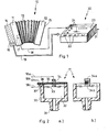
- buttons 16 connect to the right housing half 11. It goes without saying that, instead of the buttons 16, corresponding keys can also be provided. For the sake of clarity, only a part of the buttons 16 is shown in FIG. 1.
- the left housing half 12 carries in a plane, perpendicular to the plane of the drawing, further buttons 15, which are also referred to as "basses” and which serve to produce the accompaniment harmonies (chords), while the melody is usually played with the button board 14.
- each button 16 is assigned two different tones, one tone being generated when the bellows 13 is pulled and the other tone when the bellows 13 is pressed.
- the diatonic accordion 10 now has a pressure sensor 17 inside, which is connected to the interior of the bellows 13.
- a signal line 18 leads away from the pressure sensor 17.
- the buttons 16 of the accordion 10 each still work together with electrical switches, which are explained in more detail below. The switching states of these switches are transmitted via a common data line 19. It goes without saying that not only the buttons 16 of the button board 14 but also the buttons 15 can work with corresponding switches to produce the accompanying basses.
- the line 18 and the data line 19 lead to an electronic control device, which is designated overall by 20 in FIG. 1.
- the control unit 20 has operating elements 22 on a front sloping surface and further operating elements 24 in an upper, recessed operating field 23.
- the controls 22, 24 can be push buttons, knobs, sliders, toggle switches and the like. They are used in a manner known per se for adjusting the volume for the melody or the bass accompaniment, for raising or lowering the highs and lows, for setting the speed of an accompanying rhythm or for other functions such as are inherent in the technology of electronic organs are known.
- the switching states of the melody buttons 16 and possibly the accompanying bass buttons 15 are transmitted to the electronic control unit 20 in the organ according to the invention, as is the signal from the pressure sensor 17 which indicates whether the bellows 13 is being pressed or pulled or whether he is unencumbered.
- Corresponding oscillators or groups of oscillators can now be controlled in the control unit 20, so that tones are generated in parallel with the accordion playing, which serve as accompanying music.
- the accordion player can also reduce the volume of the tone of the accordion by correspondingly gentle actuation of the bellows 13 to such an extent that the tone generation of the control unit 20 comes to the fore.
- the control unit 20, regardless of the parallel melody generation to the accordion 10 can also contain rhythm units which are known per se and which ensure a corresponding accompanying rhythm.
- the signals generated by the electronic control unit 20 and used for sound generation are transmitted via an output line 21 to loudspeakers (not shown in FIG. 1).
- the pressure sensor 17 is shown in detail, specifically in two mutually perpendicular sections.
- the pressure sensor 17 consists of a housing 30, for example made of an injection-molded plastic, to which a connecting piece 31 is connected, which in turn is connected to the interior of the bellows 13.
- the housing 30 encloses a pressure chamber 32 because it is covered on its top by a membrane 33, for example a rubber membrane.
- the membrane 33 carries a fork-shaped contact element 34, as can be seen particularly well from FIG. 2 b.
- the two contacts that result from the fork shape of the contact element 34 are designated 34a (top) and 34b (bottom).
- the contact element 34 encloses a contact strip 35, which consists of an electrically non-conductive material.
- the contact strip 35 is provided on its upper side 36 and on its lower side 37 each with an electrically conductive covering, which, however, are not connected to one another.
- the diaphragm 33 bends upwards when the bellows 13 is pressed, when there is overpressure in the pressure chamber 32, so that the lower contact 34b comes into contact with the conductive coating on the underside 37 of the contact strip 35 device.
- the membrane 33 bends downward and the upper contact 34a comes into contact with the conductive coating on the upper side 36 of the contact strip 35.
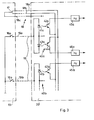
- the pressure sensor 17 can be seen at the top left, which is characterized as an electronic switch. Furthermore, one can see switches 16a, 16b assigned to the individual buttons 16, which only represent a large number of switches which can be assigned to buttons 16 and 15, respectively.
- Double optocouplers 40a, 40b and corresponding others are provided in control unit 20.
- Each double optocoupler, for example 40a consists of two light-emitting diodes (LED) 41a and 43a, to which photo transistors 42a, 44a or photo resistors are assigned.
- the anodes of the two light-emitting diodes 41a, 43a are put together at a positive potential, while the cathodes are connected together to a wire 19a which leads to the switch 16a and from there to ground.
- the associated phototransistors 42a, 44a are connected in such a way that the emitter of transistor 42a is connected to one switch contact and the emitter of transistor 44a is connected to the other switch contact of pressure sensor 17.
- the collectors of transistors 42a, 44a lead to oscillators 45a, 46a.
- the remaining double optocouplers 40b and others are connected in a corresponding manner and control corresponding oscillators 45b and others with different oscillator frequencies in each case.
- the changeover switch of the pressure sensor 17 reaches the lower switching position, for example, so that the emitters of the transistors 42a, 42b and so on are connected to a positive potential. If, for example, the button that is assigned to the switch 16a is actuated, the two light-emitting diodes 41a, 43a light up. However, since only transistor 42a is switched on and transistor 44a is not, only oscillator 45a is driven and generates a tone.
- the optocouplers used In contrast to mechanical switches, the optocouplers used also have a "soft" switching behavior, so that annoying cracking noises, whether caused indirectly by the mechanical switching elements or by bouncing or switching cracking of the mechanical contacts, do not occur.
- the optocouplers used in accordance with the invention also open up the possibility, be it with phototransistors or with photoresistors, of changing the switch-on behavior of the electrical elements light-emitting diodes / pototransistors / photoresistors by deliberately switching on delay means, in particular capacitors. This has the effect that the respective oscillator is switched on or off with a delay, so that a delay or reverberation effect can be achieved with very simple switching means.
Landscapes
- Physics & Mathematics (AREA)
- Engineering & Computer Science (AREA)
- Acoustics & Sound (AREA)
- Multimedia (AREA)
- Push-Button Switches (AREA)
- Folding Of Thin Sheet-Like Materials, Special Discharging Devices, And Others (AREA)
Applications Claiming Priority (4)
| Application Number | Priority Date | Filing Date | Title |
|---|---|---|---|
| DE8309283U | 1983-03-29 | ||
| DE8309283 | 1983-03-29 | ||
| DE19833337187 DE3337187C1 (de) | 1983-03-29 | 1983-10-13 | Elektronische Harmonika-Orgel |
| DE3337187 | 1983-10-13 |
Publications (2)
| Publication Number | Publication Date |
|---|---|
| EP0123898A2 true EP0123898A2 (fr) | 1984-11-07 |
| EP0123898A3 EP0123898A3 (fr) | 1985-10-23 |
Family
ID=25814811
Family Applications (1)
| Application Number | Title | Priority Date | Filing Date |
|---|---|---|---|
| EP84103349A Withdrawn EP0123898A3 (fr) | 1983-03-29 | 1984-03-27 | Orgue-accordéon électronique |
Country Status (2)
| Country | Link |
|---|---|
| EP (1) | EP0123898A3 (fr) |
| DE (1) | DE3337187C1 (fr) |
Cited By (2)
| Publication number | Priority date | Publication date | Assignee | Title |
|---|---|---|---|---|
| NL1007166C2 (nl) * | 1997-09-30 | 1999-03-31 | Cornelis Nicolaas J Roozendaal | Muziekinstrument met een balg. |
| CN110390924A (zh) * | 2019-07-31 | 2019-10-29 | 天津华韵乐器有限公司 | 一种电子手风琴 |
Families Citing this family (3)
| Publication number | Priority date | Publication date | Assignee | Title |
|---|---|---|---|---|
| DE3514941A1 (de) * | 1985-04-25 | 1986-01-09 | Hans Werner 7000 Stuttgart Bäcker | Ferngesteuerte tasten-musikinstrumente |
| CH715803B1 (de) * | 2019-01-18 | 2020-08-31 | Carboneon Gmbh | Handzuginstrument. |
| CN113436594A (zh) * | 2021-07-09 | 2021-09-24 | 北京东奇众科技术有限公司 | 电子手风琴贝斯按钮式键盘 |
Family Cites Families (4)
| Publication number | Priority date | Publication date | Assignee | Title |
|---|---|---|---|---|
| US3402251A (en) * | 1965-06-30 | 1968-09-17 | Bergen Lab Inc | Electrical accordion-organ |
| US3610802A (en) * | 1969-09-04 | 1971-10-05 | Bell Accordion Corp | Combination accordion-organ musical instrument |
| US3918343A (en) * | 1974-11-07 | 1975-11-11 | Thomas Joseph Gumina | Accordion pickup |
| DE2803078A1 (de) * | 1978-01-25 | 1979-07-26 | Karlheinz Neumayer | Bedienungsvorrichtung fuer musikinstrumente |
-
1983
- 1983-10-13 DE DE19833337187 patent/DE3337187C1/de not_active Expired
-
1984
- 1984-03-27 EP EP84103349A patent/EP0123898A3/fr not_active Withdrawn
Cited By (2)
| Publication number | Priority date | Publication date | Assignee | Title |
|---|---|---|---|---|
| NL1007166C2 (nl) * | 1997-09-30 | 1999-03-31 | Cornelis Nicolaas J Roozendaal | Muziekinstrument met een balg. |
| CN110390924A (zh) * | 2019-07-31 | 2019-10-29 | 天津华韵乐器有限公司 | 一种电子手风琴 |
Also Published As
| Publication number | Publication date |
|---|---|
| DE3337187C1 (de) | 1984-08-02 |
| EP0123898A3 (fr) | 1985-10-23 |
Similar Documents
| Publication | Publication Date | Title |
|---|---|---|
| DE19780109C2 (de) | Tastenmusikinstrument mit Tastenbereich-Anzeigegerät | |
| DE3150853C2 (de) | Vorrichtung zum Erkennen der Art eines Spieltastenanschlags und entsprechender Änderung der charakteristischen Merkmale eines Musikklangs bei einem elektrischen Musikinstrument (Anschlag-Aufnehmer) | |
| DE68922007T2 (de) | Tastenkraftermittlung für automatische Klaviere. | |
| DE3303859C2 (de) | Einrichtung zum Einstellen einer Klangfarbe | |
| DE2526458A1 (de) | Elektronisches musikinstrument mit akkorderzeugung | |
| DE2421633C3 (de) | Elektronische Orgel mit automatisierter Akkordbildung | |
| DE2053245B2 (de) | Elektronisches musikinstrument | |
| DE3332477A1 (de) | Elektronisches musikinstrument mit einer vorrichtung zur lokalisierung von klangbildern | |
| DE2526457B2 (de) | Elektronisches Musikinstrument | |
| DE3337187C1 (de) | Elektronische Harmonika-Orgel | |
| DE3304995C2 (de) | Rein gestimmtes elektronisches Musikinstrument | |
| US3305620A (en) | Organ chord switching mechanism | |
| DE2555083A1 (de) | Registriereinrichtung fuer elektronische musikinstrumente | |
| DE2526624A1 (de) | Fussbetaetigte steuereinrichtung fuer elektronische musikinstrumente | |
| DE2308963A1 (de) | Elektronisches musikinstrument | |
| CH643671A5 (de) | Elektronisches musikinstrument. | |
| DE19581930B4 (de) | Klavier mit einem eingebauten elektronischen Musikinstrument | |
| DE2511199A1 (de) | Elektronisches musikinstrument | |
| DE3712706C2 (fr) | ||
| CH614303A5 (en) | Electronic tone-generating device for installation into a piano, and piano having the tone-generating device | |
| DE2807873B1 (de) | Registriereinrichtung fuer elektronische Musikinstrumente | |
| DE2446428A1 (de) | Schaltung zur transposition und bildung von akkorden | |
| DE3343855C2 (fr) | ||
| DE102004030643A1 (de) | Steueranordnung für ein Musikinstrument, insbesondere ein Akkordeon | |
| DE584092C (de) | Musikinstrument mit Tonerzeugung durch elektrische Schwingungskreise |
Legal Events
| Date | Code | Title | Description |
|---|---|---|---|
| PUAI | Public reference made under article 153(3) epc to a published international application that has entered the european phase |
Free format text: ORIGINAL CODE: 0009012 |
|
| AK | Designated contracting states |
Designated state(s): AT CH FR IT LI |
|
| PUAL | Search report despatched |
Free format text: ORIGINAL CODE: 0009013 |
|
| AK | Designated contracting states |
Designated state(s): AT CH FR IT LI |
|
| STAA | Information on the status of an ep patent application or granted ep patent |
Free format text: STATUS: THE APPLICATION IS DEEMED TO BE WITHDRAWN |
|
| 18D | Application deemed to be withdrawn |
Effective date: 19860624 |