EP0123969A2 - Procédé pour la fabrication d'un feutre tubulaire sans fin, et appareil pour exécuter ce procédé - Google Patents
Procédé pour la fabrication d'un feutre tubulaire sans fin, et appareil pour exécuter ce procédé Download PDFInfo
- Publication number
- EP0123969A2 EP0123969A2 EP84103904A EP84103904A EP0123969A2 EP 0123969 A2 EP0123969 A2 EP 0123969A2 EP 84103904 A EP84103904 A EP 84103904A EP 84103904 A EP84103904 A EP 84103904A EP 0123969 A2 EP0123969 A2 EP 0123969A2
- Authority
- EP
- European Patent Office
- Prior art keywords
- line
- marking
- felt
- tubular felt
- marking line
- Prior art date
- Legal status (The legal status is an assumption and is not a legal conclusion. Google has not performed a legal analysis and makes no representation as to the accuracy of the status listed.)
- Granted
Links
Images




Classifications
-
- D—TEXTILES; PAPER
- D04—BRAIDING; LACE-MAKING; KNITTING; TRIMMINGS; NON-WOVEN FABRICS
- D04H—MAKING TEXTILE FABRICS, e.g. FROM FIBRES OR FILAMENTARY MATERIAL; FABRICS MADE BY SUCH PROCESSES OR APPARATUS, e.g. FELTS, NON-WOVEN FABRICS; COTTON-WOOL; WADDING ; NON-WOVEN FABRICS FROM STAPLE FIBRES, FILAMENTS OR YARNS, BONDED WITH AT LEAST ONE WEB-LIKE MATERIAL DURING THEIR CONSOLIDATION
- D04H18/00—Needling machines
- D04H18/02—Needling machines with needles
Definitions
- the invention relates to a method for producing and / or treating an endless tubular felt or similar tubular structure, in which material, for example a nonwoven fibrous web, a coating, longitudinal threads or the like, is continuously produced in this direction on the tubular felt which is at least partially manufactured and rotates in the circumferential direction Applied width and / or the tubular felt is treated in a width, for example flamed or needled, which is less than that of the tubular felt, the application or treatment by a relative movement of the or to the tubular felt transversely to its direction of travel helically - if necessary with partial overlap - done.
- material for example a nonwoven fibrous web, a coating, longitudinal threads or the like
- the invention further relates to a device for performing this method with at least two spaced-apart transport rollers for the already manufactured th part of the tubular felt and with a feed device for applying the material to and / or with a treatment device for the already produced part of the tubular felt, a displacement device being provided for the relative movement between the hose felt and the feed device or the treatment device in the axial direction of the transport rollers .
- the device has two mutually adjustable transport rollers over which the part of the tubular felt that has already been produced runs.
- a non-woven web is fed continuously in the direction of rotation of the tubular felt, in such a way that this non-woven web partially overlaps with an edge of the already made tubular felt. After laying the nonwoven fleece, it is needled with the tubular felt.
- the device disclosed in DE-AS 23 24 985 works in reverse kinematic fashion. With this device, it is not the tubular felt that is moved transversely, but rather the feeding device for the nonwoven fibrous web. However, the tubular felt is formed in the same way by screwing the nonwoven web together with partial overlap.
- nonwoven webs are placed in such a way that there are no changes in basis weight or thickness. This can occur, for example, due to uncontrolled migration of the hose on the transport rollers or due to fluctuations in the transverse movement of the feed device.
- treatment and processing measures such as flaming, needles, brushes or the like.
- This can also be done in such a way that a corresponding device of small width is pushed over the width of the tubular felt rotating in the circumferential direction or, conversely, the tubular felt is moved transversely under the stationary device.
- Similar kinematic conditions apply to the treatment of hose felts or the corresponding hose hose form given in roll calenders.
- threads that run at a distance from one another can also be applied to a tubular felt to form longitudinal drainage channels, in which one or more threads are passed side by side through the gaps of a reed onto the surface of the tubular felt.
- a tubular felt By moving either the tubular felt or the feed device for the threads transversely, they receive a helical course on the tubular felt, it also being essential here that the spacing between the applied threads is as uniform as possible.
- the invention is based on the object of improving the method mentioned at the outset in such a way that there is a uniform application of material or a uniform treatment of the tube fill.
- Another object is to find a device for performing this method.
- the first-mentioned object is achieved according to the invention by continuously applying at least one marking line in the running direction in the circumferential direction in the circumferential direction, the position or the distance of which from a neighboring marking line in the running direction behind it is scanned contactlessly as the actual value, the relative movement in each case is set so that the sampled actual value deviates as little as possible from a certain target value.
- the marking line serves here, as it were, as an indicator for the actual relative movement between tubular felt and the application or treatment, whereby the cross-offset of the Mar The marking line at a distance from the point where it is applied is scanned without contact and then this actual value is compared with a target value.
- the actual value can then be adjusted to the setpoint by readjusting the drive for the transverse movement, so that the most uniform possible transverse movement is achieved.
- This uniform transverse movement ensures, for example when applying a nonwoven web, that the continuous construction of the tubular felt takes place optimally, the thickness being largely the same over the entire width.
- the marking line can be scanned at different locations. It has proven to be advantageous to scan the position of the marking line before the tubular felt has made a full revolution with the marking line. In this area, the transverse movement which has meanwhile been carried out becomes particularly clear and thus easily palpable, but with the disadvantage that this is only detected shortly before a complete revolution is completed.
- the distance between the revolutions or revolutions of a marking line can also be scanned.
- the marking line then forms a helical line on the already finished tubular felt, the distance between the adjacent parts of the line being a measure of the respective transverse movement.
- Such a distance measurement can also be carried out by g e if there is first a first one, behind it in the running direction and at a transverse distance to this one second marking line is applied and then the distance between the two marking lines is scanned. This has the advantage that one does not have to wait for a full revolution of the marking line to scan the distance.
- the marking line is to be applied there according to the invention does not mean that it must be continuous. It is also sufficient if the marking line is composed of dashes or dots. Washable paint can be used as the material for the marking line, for example. Has proven to be particularly useful. to apply a marking thread as a marking line, which contrasts strongly in color with the color of the tubular felt. In this case, yarns which are as smooth as possible are expediently suitable as the marking thread, in particular if the marking thread, as is particularly advantageous, is applied with the already produced part of the tubular felt before the consolidation of a nonwoven fiber web. In this way, the marking thread is needled with the tubular felt, so that it then no longer changes its position. Despite this vernade lung, it can then be easily removed after it has been scanned without damaging the tubular felt.
- optical methods are particularly suitable as scanning methods.
- an apparatus for carrying out this method is provided by at least one application device for continuously applying the marking line to the tubular felt in its circumferential direction and characterized by a non-contact scanning device for detecting the position of the marking line or its distance from an adjacent marking line in the running direction behind the application device (s), the application device (s) and the scanning device being arranged immovably with respect to one another when the tube film is moved transversely and in the case of a transversely moving feed device or treatment device, are coupled to the displacement device and the scanning device is connected to an electronic evaluation device for determining the difference between the actual value supplied by the scanning device for the position or the distance of the marking line (s) and the target value specified for this purpose and the evaluation device is connected to a control device for determining a manipulated value for adjusting the drive of the displacement device in the direction of minimizing the difference.
- the device of the generic type is therefore provided with a control device for carrying out the method according to the invention, the actual value of the transverse movement for the control device being determined from the position of the marking line or the distance between two adjacent ones beard marking lines is obtained.
- the control device acts on the displacement device in such a way that the actual transverse movement of the tubular felt corresponds as uniformly as possible to a predetermined target value.
- the application device (s) is or are arranged in the running direction in front of the consolidation device, which is particularly advantageous if a marking thread is applied as the marking line, since this is then fixed on the tubular felt by the consolidation device .
- a second application device can be arranged behind the first, viewed in the direction of travel. The measure of the distance between the marking lines applied by the two application devices then corresponds to the actual transverse movement of the tubular felt.
- the scanning device in the region of two adjacent parts of the marking line after more than one revolution and to design the scanning device for detecting the distance between the two neighboring parts of this marking line. In this case, the distance is also scanned as the actual value, but only the application of a marking line is necessary.
- the scanning device in the area of the marking line shortly before the end of a revolution arranged and the scanning device is designed for detecting the position of the marking line.
- This scanning device has proven itself in practice despite the relatively large distance between the application of the marking line and the scanning, since the change in position is particularly clear in this area when the transverse movement changes.
- the marking line (s) contrast or contrast visually with the tubular felt and that the scanning device works optoelectronically.
- This is believed to be the simplest method for applying a marking line and scanning it.
- This can, for example, have a light transmission measuring device, as is known as a scanner or light barrier measuring device.
- the video camera should be arranged so that the marking line (s) runs parallel to the scanning lines of the video camera, in order in this way to obtain a video signal with a constant SignaLampLitude between two line-tipping pulses.
- the video camera and the marking line (s) are coordinated with one another in such a way that the marking line (s) takes up at least six scanning lines. This serves to provide a clear video signal regardless of to get any glitches.
- the evaluation device expediently has a detector circuit for detecting the marking line (s) and a counting circuit for counting the scanning lines from the beginning of the image to the video signal of the marking line (s) and / or between two such video signals, the counting value being the actual value for the control device.
- the detector circuit can be designed in such a way that it has a shift register clocked by the tilting pulses of the video camera and reset by the tilting pulses of the video camera for the shifting of tilting pulses, the video signal controlling an input port such that only the tilting video signals when present the marking line (s) enter the shift register.
- An AND circuit should be connected to the shift register, which only emits a signal when three successive line break pulses are present. In this way, the signal output is largely secured against interference when a marking is detected.
- the counting circuit consists of a line tipping pulse counter, a line tipping pulse memory connected to it and a counter acted upon by a multivibrator, this counter being controlled by every second tipping pulse in such a way that the line tipping pulse memory stores a takeover pulse for taking over the count value in the line tipping pulse
- Line tilt pulse counter receive a clear pulse before the next line tilt pulse arrives.
- the line break pulses of two fields recorded in the line break pulse counter are put into a memory and the line break pulse counter is reset to its initial position, so that he can again capture the line break pulses of two fields.
- a gate can be connected in front of the input of the line tilt pulse counter, which is controlled by the detector circuit via a counting flip-flop in such a way that it is blocked by a signal from the detector circuit when a signal is present and opens when there is an image switch pulse. In this way, only the line tipping pulses arrive in the line tipping pulse counter that occur from the beginning of a field until the complete detection of the marking line.
- a data flip-flop is provided in parallel with the counting flip-flop, which can be switched to the gate instead of the counting flip-flop and is controlled by the counting flip-flop and the detector circuit in such a way that when a first signal from the detector circuit is present, the gate opened and locked again when a second signal is present.
- the control device is expediently designed as a PI controller. Such a controller has proven to be sufficient so that the arrangement of a PID controller is not necessary.
- the setpoint input and the output of the control value are expediently carried out via optocouplers so that the microprocessor is galvanically isolated from the input or output.
- the application device (s) has or have a spool provided with a marking thread.
- a storage feeder should be arranged between the spool and the tubular felt so that the marking thread can be removed from the spool without interference.
- the marking thread should be guided onto the tubular felt by a guide plate provided with a guide groove.
- a take-off device for the marking thread should be provided, which consists of a motor-driven spool.
- switches are expediently provided for controlling the bobbin drive as a function of the run-off angle of the marking thread, so that precise synchronization with the rotation of the hose felt can be dispensed with.
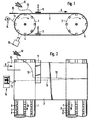
- the device shown in FIGS. 1 and 2 essentially consists of two transport rollers 1, 2 which are arranged axially parallel to one another and around which a partially built-up tubular felt 3 is guided.
- the transport rollers have grooves 4, 5, distributed in parallel to their axes, in their transport surfaces, in which transport chains 6, 7 are guided.
- These wear needle pieces 8, 9 which surround the tubular felt 3.
- the transport rollers 1, 2 turn the hose felt 3 in the direction of the arrow A.
- the hose becomes simultaneous felt 3 moved transversely by means of the transport chains 6, 7 and needle pieces 8, 9, namely in the direction of the arrows B, C.
- a nonwoven web 10 is placed on the top edge of the tubular felt 3 in FIG. 2 and runs in from a brim in the direction of the arrow D.
- the fiber fleece web 10 overlaps two thirds of its width with the already assembled tubular felt 3. It is consolidated by means of a needle machine 11 arranged behind the first transport roller 1 and connected to the tubular felt 3. From Figure 1 it can be seen that it is a double-working needle machine 11, which solidifies the tubular felt 3 both in the upper and in the lower run. Up to this point, the device essentially corresponds to that according to DE-PS 16 6o 765.
- a marking thread 13 is drawn off from a cross-wound bobbin 12 and placed on the tube felt 3 at a specific point by means of devices described in more detail below. This is done in front of the needle machine 11 so that the marking thread 13 is needled with the tubular felt 3. The marking thread 13 then moves with the tubular felt 3, executing the helical line shown in FIG. 2. In the area of the transport roller 1, it is pulled off a roll-off device 14 again from the surface of the tubular felt 3 and rolled up. Previously, its position assumed due to the transverse movement was recorded by a video camera 15 with a Vidikon tube.
- the width of the marker thread 13 and the arrangement The video camera 15 is matched to one another in such a way that the marking thread 13 runs parallel to the scanning lines of the video camera 15 into the recorded video image and the video camera 15 detects the marking thread 13 with at least 6 scanning lines, ie 3 scanning lines per field.
- lighting fixtures can also be attached so that the marking thread 13 stands out as strongly as possible from the surface of the tubular felt 3. For this purpose, it should also contrast as much as possible with the color of the tubular felt 3, which is generally achieved with a deep black thread, since the tubular felt 3 is generally very light.
- a thread that is as smooth as possible, but that should have a fiber structure so that it can be needled and fixed into the surface of the tubular felt 3 as the marking thread 13.
- a marking thread 13 a marking line can of course also be applied with the help of colored pencils, also with fluorescent colors.
- the application of metal threads is also conceivable if the scanning device is then adapted accordingly.
- FIGS. 3 to 5 show how the tubular felt 3 is built up in stages.
- a further fiber nonwoven web b is then placed on this, in such a way that two thirds of its width come to lie on the fiber nonwoven web a and one third of the width protrudes on the left edge.
- Another third non-woven nonwoven web c is then applied to the nonwoven web b by two thirds overlapping and another nonwoven web d is applied to this.
- the subsequent nonwoven fibrous webs lay on top of the previous nonwoven fibrous web in the same way as the nonwoven fibrous web d.
- the resulting tubular felt consists of three layers of fiber fleece webs that are needled together.
- the transverse movement is optimal in the example according to FIG. 3, so that the weight per unit area is uniform.
- Figure 4 shows in principle the same structure of a tubular felt, only that in this case the transverse movement in the direction of the arrow E is too great. In this way, the overlap of the nonwoven web b 'over the nonwoven web a' is less than two thirds L of their width.
- the FaservLiesbahn c 'and of course also with the FaservLiesbahn d' whereby it can be seen that there is a gap between the respective upper parts of the FaservLiesbahn c 'and d', where the thickness - theoretically - only doubles
- the thickness of a nonwoven fibrous web is three times the desired thickness instead of the desired. Such a change in thickness is detrimental to the properties of the tubular felt, but has frequently occurred with the device according to DE-PS 16 6o 765.
- the application device for the marking thread 13 is shown in more detail in the side view, the arrow A indicating the direction of movement of the tube felt 3.
- the marking thread 13 is first wound on a package 12, the package 12 being provided with an outlet net 16.
- the marking thread 13 is removed from the cross winder 12 overhead and passes via the guide eyelets 17, 18, 19 to a storage feeder 2 0 , as is known from embroidery. This periodically fills the yarn store on its bobbin and ensures constant thread take-up tension.
- the marking thread 13 is drawn off from the storage feeder 20 by the movement of the tubular felt 3, whereby it is placed on the tubular felt 3 by means of a guide plate 21, which has guide grooves for this purpose, and is then attached directly by the needle machine 11. This arrangement ensures that the marking thread 13 is always placed on the tubular felt 3 at the same point and with the same possible tension.
- the trigger device 14 shown in FIG. 7 has a base plate 22, on which a trigger coil 23 is rotatably mounted, which is driven by a geared motor 24.
- the marking thread 13 runs into the take-off device 14 - from the one not shown here Tubing felt 3 going out - via a slotted eyelet 25, then passes through a fixed eyelet 26 and then an eyelet 28 which is guided transversely on a rail 27 before it reaches the take-off spool 23.
- the eyelet 28 is shifted from time to time so that the marking thread 13 is wound evenly over the width of the take-off spool 23.
- the geared motor 24 is set in such a way that more and more marking thread 13 is drawn off with the take-off spool 23 than is necessary.
- the marking thread 13 moves into the position 13a shown in broken lines due to the tension then exerted.
- a switch 30 is actuated via a sensor 29, which switches off the geared motor 24, so that the marking thread 13 is no longer wound onto the take-off spool 23.
- the marker thread 13 then soon assumes the solid position 13b, in which it actuates the sensor 31 of a switch 32. This switches the geared motor 24 on again, so that the marking thread 13 is wound up again. In this way, the removal of the marking thread 13 from the tubular felt 3 is easy.
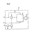
- the block diagram shown in FIG. 8 relates to a detector circuit 33 for an evaluation device shown in more detail in FIG. 9, which is connected to the video camera 15 (FIG. 1).
- the image projected onto their Vidikon tube is - as usual - broken down into 625 scan lines, with every other line being scanned in succession. A picture is thus broken down into two fields and transmitted.
- the video camera 15 delivers a video signal, the voltage of which is proportional to the brightness of the line being scanned Is part of the picture.
- the video camera 15 is arranged such that the marking thread 13 runs parallel to the scanning lines, so that the marking thread is scanned by the Videkon tube as darkened times, whereby a corresponding video signal is produced.
- pulses are also picked up by the video camera 15, which once indicate the beginning of the scanning of a field, which signal the so-called image flip pulses and the start of the scanning of a line, the so-called line flip pulses.
- the detector circuit 33 has a shift register 34, at whose input line break pulses F are present. Via a parallel line 35, the tilting pulses also simultaneously indicate the clock for the shift register 34.
- the image tilt pulses G are received via a further input on the shift register 34. They have the task of returning the shift register 34 to a defined initial state when a field has been scanned.
- the video signal H arrives first in an amplifier 36 and then in a threshold switch 37. This opens a gate 38 as soon as a video signal H arrives that has scanned a dark line originating from the marking thread 13.
- a line break pulse F reaches the shift register 34 via the then opened gate. If the next line scanned is also dark, the next line break pulse F also goes into the shift register. The same thing happens when the third line scanned is dark.
- An AND circuit 39 connected to the shift register 34 only lets out a signal if at least three successive line tilting pulses F in the shift register 34 have been pushed through.
- the then outgoing SignaL means "Marking thread recognized".
- the shift register 34 is reset by the image flip pulse G and is then ready to receive line flip pulses F from the second field.
- the gate 38 is then opened again accordingly for the line tilting pulses F as soon as a video signal H. from the scanning of dark lines is present. An output signal is therefore generated for each field behind the AND circuit 39.
- FIG. 9 shows the block circuit diagram of the entire evaluation device, the detector circuit 33 being shown here only as a single block.
- the line break pulses F go via a line 40 to a gate 41 and from there to a line break pulse counter 42, where they are counted when the gate 41 is open.
- the gate 41 is controlled via a multiple switch 43. In the drawn position of the multiple switch 43, the gate 41 is continuously open. In this way, all of the line break pulses F reach the line break pulse counter 42.
- the gate 41 is controlled by a counting flip-flop 44. T his Zählflipflop 44 erphasett to a d.ie via line 45 Rudkippimpulse 6. These control the Zählflipflop 44 so that the gate is opened 41st At the beginning of each field, the line tilting pulses F can thus reach the line tilting pulse counter 42.
- the gate 41 remains open until the detector circuit 33 emits a control pulse for switching the counting flip-flop 44. This happens - as explained in more detail in the description of FIG. 8 - whenever a total of three dark lines are scanned and the associated ones Row flip pulses F through which shift register 34 have been shifted.
- the gate 41 is closed, so that the line-tipping pulse counter 42 no longer receives line-tipping pulses F.
- the counting flip-flop 44 is switched over again by the image tilting pulse G, so that the gate 41 is opened again.
- a data flip-flop 46 is arranged in parallel with the counting lip 44. It is then connected to the gate 41 by means of the multiple switch 43 when the distance between two marking threads is to be detected. For this purpose, the data flip-flop 46 is brought into a defined position at the beginning of each field by means of the image tilt pulse G via the line 45, the counting flip-flop 44 and the line 47, in which the gate 41 is locked.
- the line flip pulse counter 42 therefore initially does not receive any line flip pulses F.
- the data flip-flop 46 is only changed over by an output pulse from the detector circuit 33 and then opens the gate 41. This occurs - as described above - when three dark lines have been scanned, that is to say a first marker thread has been detected is.
- the second marker thread lying next to it will then be detected by again scanning three dark lines and then generating a corresponding output signal in the detector circuit 33 for switching the data flip-flop 46.
- the gate 41 is closed again by this switching.
- the line-tipping pulse counter 42 then only counted the line-tipping pulses F that occurred between the two marking threads captured by the video camera next to one another, for the sake of accuracy it should be added that the first three line-tipping pulses F, which occur when the second marking thread is detected, are also counted . In this case, too, the line break pulses F of both fields are added together in the line break pulse counter 42.
- the line tipping pulse counter 43 is connected to a line tipping pulse memory 48, to which the count value in the line tipping pulse counter 42 is transferred after two fields have been scanned. This is done by means of a further counter 49, which is acted upon by a high-frequency multivibrator 50.
- the image tilting pulses G also enter the counter 49 via a line 51, a divider 2: 1 52 being interposed. The divider 52 ensures that only every second image tilt pulse G reaches the counter 49.
- Three outputs are connected to the line break pulse memory 48, the first output leading to a digital display 55 for the counter reading in the line break pulse memory 48, the second output forming the binary output for the subsequent control device and the third output going to a DigitaL analog converter, for example one Control plotter.
- line 53 there is also a line 58 which supplies synchronization pulses to the computer shown in FIG. 1o.
- Figure 1o shows the block diagram of the control device for the PI controller, with which the drive of the transport chains 6, 7 ( Figure 2) is to be controlled so that the actual transverse movement of the tubular felt 3 corresponds as constant as possible to a certain setpoint.
- a computer based on a microprocessor is installed in the control device. Appropriate software controls this microprocessor 59.
- the target value for the transverse movement of the tubular felt 3 is specified via a latching switch 6o.
- This one has Connection to a relay block 61. This is currently in a position in which the latching switch 6 0 is connected directly to a converter 62 for the drive motor of the transport chains 6, 7.
- This drive motor not shown here, is therefore not regulated at a glance, but only receives the target value.
- the converter 62 receives this specification in particular when the microprocessor 59 is switched off or when faults have occurred.
- the position of the latching switch 60 and thus the target value are then read into the microprocessor 59 via optocouplers 63, an input multiplexer 64 and an input port 65.
- the control value After the control value has been calculated, it is sent to the converter 62 via the output port 66, the output multiplexer 67, the optocouplers 63 and the relay block 61. Before this, however, the relay block 61 must be brought into the automatic position, which is done with the aid of a control circuit 68.
- the control circuit 68 is controlled on the one hand by a further detector circuit 69, which reports to the control circuit 68 whether the needle machine 11 is in operation or not. In the latter case, the edge control circuit 68 causes the microprocessor 59 to no longer calculate a new control value.
- the control circuit 68 is also controlled by an operating part 7o. From this operating part 7o, the relay block 61 can be switched manually, for example to interrupt the activity of the microprocessor 59. For the rest, the operating part 7o is used to send the control factors to the microprocessor 59 for the P and I portion. These must be adapted to the time constant of the control path, which is determined by the length of the tubular felt and its speed of rotation.
- a selection circuit 71 is provided for successively reading in the control factors and is connected to the microprocessor 59 via an input port 72 and an output port 73.
- the operating part 7o is connected to the microprocessor 59 via a further input port 74, via which a start pulse can be given in the microprocessor 59, which sets the microprocessor 59 in a defined starting position.
- a further switch causes the control circuit 68 to switch the relay block 61 into the automatic position.
- the evaluation device 75 shown in more detail in FIGS. 8 and 9 is shown here only by means of a BLock without further specification.
- the binary output 56 shown in FIG. 9 leads out of this evaluation device 75 and goes to a buffer stage 76, which gives the count value of the line-to-point pulses F to the microprocessor 59 via the input port 77.
- Each newly determined value triggers an interrupt 78, as a result of which the microprocessor 59 is signaled that the count value is stable at the input port 77 for a defined period of time.
- the microprocessor 59 reads in a value every second, waiting beforehand for the synchronization pulse coming from the counter 49 in FIG. Appropriate software then performs certain checks before the microprocessor 59 calculates a manipulated variable. This includes, in particular, checking whether there is actually a marking thread in the camera area. This is not the case, there is a jump to an alarm loop with a corresponding display and then a program abort. If the controls indicate that the microprocessor 59 is to calculate a set value, then the count values of the line break pulses given to the microprocessor 59 are first compared with the correspondingly specified SoLL value and the difference is formed. The proportional and integral values are then determined and the control value is then calculated. A conversion of the initially binary control value into a BCD value then takes place, which is then output. Then the jump back and waiting for your own seconds.
Landscapes
- Engineering & Computer Science (AREA)
- Textile Engineering (AREA)
- Treatment Of Fiber Materials (AREA)
Priority Applications (1)
| Application Number | Priority Date | Filing Date | Title |
|---|---|---|---|
| AT84103904T ATE27316T1 (de) | 1983-04-30 | 1984-04-07 | Verfahren zum herstellen eines endlosen schlauchfilzes sowie vorrichtung zum durchfuehren dieses verfahrens. |
Applications Claiming Priority (4)
| Application Number | Priority Date | Filing Date | Title |
|---|---|---|---|
| DE3315834 | 1983-04-30 | ||
| DE3315834 | 1983-04-30 | ||
| DE19833319241 DE3319241A1 (de) | 1983-04-30 | 1983-05-27 | Verfahren zum herstellen eines endlosen schlauchfilzes sowie vorrichtung zum durchfuehren dieses verfahrens |
| DE3319241 | 1983-05-27 |
Publications (3)
| Publication Number | Publication Date |
|---|---|
| EP0123969A2 true EP0123969A2 (fr) | 1984-11-07 |
| EP0123969A3 EP0123969A3 (en) | 1985-05-02 |
| EP0123969B1 EP0123969B1 (fr) | 1987-05-20 |
Family
ID=25810448
Family Applications (1)
| Application Number | Title | Priority Date | Filing Date |
|---|---|---|---|
| EP84103904A Expired EP0123969B1 (fr) | 1983-04-30 | 1984-04-07 | Procédé pour la fabrication d'un feutre tubulaire sans fin, et appareil pour exécuter ce procédé |
Country Status (3)
| Country | Link |
|---|---|
| US (1) | US4614969A (fr) |
| EP (1) | EP0123969B1 (fr) |
| DE (2) | DE3319241A1 (fr) |
Cited By (7)
| Publication number | Priority date | Publication date | Assignee | Title |
|---|---|---|---|---|
| AT384834B (de) * | 1985-06-21 | 1988-01-11 | Fehrer Textilmasch | Vorrichtung zum herstellen von genadelten papiermaschinenfilzen |
| DE3937651A1 (de) * | 1988-11-22 | 1990-05-23 | Fehrer Textilmasch | Verfahren und vorrichtung zum aufnadeln eines vliesbandes auf eine umlaufende, endlose traegerbahn |
| EP0464258A1 (fr) * | 1990-06-13 | 1992-01-08 | Thomas Josef Heimbach GmbH & Co. | Feutre, en particulier pour machine à papier et son procédé de fabrication |
| DE4229749A1 (de) * | 1991-09-16 | 1993-03-18 | Fehrer Textilmasch | Vorrichtung zum aufbringen eines vliesbandes auf eine endlos umlaufende traegerbahn |
| DE4229750A1 (de) * | 1991-09-16 | 1993-03-18 | Fehrer Textilmasch | Vorrichtung zum aufbringen eines vliesbandes auf eine endlos umlaufende traegerbahn |
| DE4229579A1 (de) * | 1991-09-16 | 1993-04-01 | Fehrer Textilmasch | Vorrichtung zum aufbringen eines vliesbandes auf eine endlos umlaufende traegerbahn |
| DE102007000579A1 (de) | 2007-10-26 | 2009-04-30 | Voith Patent Gmbh | Papiermaschinenbespannungen, insbesondere für Pressfilze, und Verfahren zu deren Herstellung |
Families Citing this family (14)
| Publication number | Priority date | Publication date | Assignee | Title |
|---|---|---|---|---|
| US4777706A (en) * | 1987-09-14 | 1988-10-18 | Morrison Berkshire, Inc. | Apparatus for manufacturing endless needled paper machine felts |
| JPH0734956Y2 (ja) * | 1989-12-29 | 1995-08-09 | 日本フエルト株式会社 | チューブラニードリング装置 |
| US5268076A (en) * | 1990-06-13 | 1993-12-07 | Thomas Josef Heimbach Gmbh & Co. | Spiral wound papermaking-machine felt |
| US5202170A (en) * | 1991-04-08 | 1993-04-13 | Wangner Systems Corporation | Papermaking felt with a non-spiralled machine direction fiber batt |
| US5864931A (en) * | 1991-05-23 | 1999-02-02 | Thomas Josef Heimbach Gmbh & Co. | Felt, in particular a papermaking-machine felt, and method for its manufacture |
| US5349728A (en) * | 1992-05-27 | 1994-09-27 | Nippon Felt Co., Ltd. | Magnetic position marker and control system for production of felt |
| JPH11293583A (ja) * | 1998-04-10 | 1999-10-26 | Mitsubishi Heavy Ind Ltd | 多孔質ウェブの連続乾燥装置 |
| US6927857B2 (en) * | 2002-03-09 | 2005-08-09 | Kimberly-Clark Worldwide, Inc. | Process for the detection of marked components of a composite article using infrared blockers |
| US6888143B2 (en) * | 2002-03-09 | 2005-05-03 | Kimberly-Clark Worldwide, Inc. | Apparatus and method for inspecting pre-fastened articles |
| US6900450B2 (en) | 2002-03-09 | 2005-05-31 | Kimberly-Clark Worldwide, Inc. | Method and apparatus for inferring item position based on multiple data |
| US6919965B2 (en) | 2002-03-09 | 2005-07-19 | Kimberly-Clark Worldwide, Inc. | Apparatus and method for making and inspecting pre-fastened articles |
| US6885451B2 (en) | 2002-03-09 | 2005-04-26 | Kimberly-Clark Worldwide, Inc. | Infrared detection of composite article components |
| US7123765B2 (en) * | 2002-07-31 | 2006-10-17 | Kimberly-Clark Worldwide, Inc. | Apparatus and method for inspecting articles |
| WO2017203524A1 (fr) * | 2016-05-24 | 2017-11-30 | Twine Solutions Ltd. | Système, machine et procédé permettant de traiter des fils ou des parties de ces derniers |
Family Cites Families (5)
| Publication number | Priority date | Publication date | Assignee | Title |
|---|---|---|---|---|
| US3101175A (en) * | 1959-09-23 | 1963-08-20 | Wald Ind Inc | Road striping machine with electronic sight |
| US3497413A (en) * | 1964-01-20 | 1970-02-24 | Owens Corning Fiberglass Corp | Apparatus for making a tubular body of fibrous glass |
| DE1660765A1 (de) * | 1967-09-15 | 1971-08-05 | Richard Dilo | Verfahren zum Herstellen endloser Papiermaschinenfilze oder technischer Schlauchfilze und Vorrichtung zum Durchfuehren des Verfahrens |
| FI53844C (fi) * | 1972-06-27 | 1978-08-10 | Tampereen Verkatehdas Oy | Foerfarande foer tillverkning av en naolad aendloes maskinfilt |
| EP0005462B1 (fr) * | 1978-05-22 | 1983-06-08 | Siemens Aktiengesellschaft | Procédé pour positionner deux objets à ajuster l'un sur l'autre |
-
1983
- 1983-05-27 DE DE19833319241 patent/DE3319241A1/de not_active Withdrawn
-
1984
- 1984-04-07 EP EP84103904A patent/EP0123969B1/fr not_active Expired
- 1984-04-07 DE DE8484103904T patent/DE3463797D1/de not_active Expired
- 1984-04-24 US US06/603,324 patent/US4614969A/en not_active Expired - Lifetime
Cited By (13)
| Publication number | Priority date | Publication date | Assignee | Title |
|---|---|---|---|---|
| AT384834B (de) * | 1985-06-21 | 1988-01-11 | Fehrer Textilmasch | Vorrichtung zum herstellen von genadelten papiermaschinenfilzen |
| DE3937651A1 (de) * | 1988-11-22 | 1990-05-23 | Fehrer Textilmasch | Verfahren und vorrichtung zum aufnadeln eines vliesbandes auf eine umlaufende, endlose traegerbahn |
| FR2639367A1 (fr) * | 1988-11-22 | 1990-05-25 | Fehrer Textilmasch | Procede et dispositif pour piquer un ruban de voile sur une bande-support sans fin tournant en continu |
| US4962576A (en) * | 1988-11-22 | 1990-10-16 | Textilmaschinenfabrik Dr. Ernst Fehrer Aktiengesellschaft | Process and apparatus for needling a non-woven strip to a revolving endless carrier web |
| EP0464258A1 (fr) * | 1990-06-13 | 1992-01-08 | Thomas Josef Heimbach GmbH & Co. | Feutre, en particulier pour machine à papier et son procédé de fabrication |
| DE4229749A1 (de) * | 1991-09-16 | 1993-03-18 | Fehrer Textilmasch | Vorrichtung zum aufbringen eines vliesbandes auf eine endlos umlaufende traegerbahn |
| DE4229750A1 (de) * | 1991-09-16 | 1993-03-18 | Fehrer Textilmasch | Vorrichtung zum aufbringen eines vliesbandes auf eine endlos umlaufende traegerbahn |
| FR2681344A1 (fr) * | 1991-09-16 | 1993-03-19 | Fehrer Textilmasch | Dispositif pour placer un ruban de voile de carde sur une bande-support tournant sans fin. |
| FR2681345A1 (fr) * | 1991-09-16 | 1993-03-19 | Fehrer Textilmasch | Dispositif pour placer un ruban de voile de carde sur une bande-support tournant sans fin. |
| DE4229579A1 (de) * | 1991-09-16 | 1993-04-01 | Fehrer Textilmasch | Vorrichtung zum aufbringen eines vliesbandes auf eine endlos umlaufende traegerbahn |
| DE4229750C2 (de) * | 1991-09-16 | 1995-03-23 | Fehrer Textilmasch | Vorrichtung zum Aufbringen eines Vliesbandes auf eine endlos umlaufende Trägerbahn |
| DE4229579C2 (de) * | 1991-09-16 | 1995-11-09 | Fehrer Textilmasch | Vorrichtung zum Aufbringen eines Vliesbandes auf eine endlos umlaufende Trägerbahn |
| DE102007000579A1 (de) | 2007-10-26 | 2009-04-30 | Voith Patent Gmbh | Papiermaschinenbespannungen, insbesondere für Pressfilze, und Verfahren zu deren Herstellung |
Also Published As
| Publication number | Publication date |
|---|---|
| DE3463797D1 (en) | 1987-06-25 |
| EP0123969A3 (en) | 1985-05-02 |
| US4614969A (en) | 1986-09-30 |
| EP0123969B1 (fr) | 1987-05-20 |
| DE3319241A1 (de) | 1984-11-15 |
Similar Documents
| Publication | Publication Date | Title |
|---|---|---|
| EP0123969B1 (fr) | Procédé pour la fabrication d'un feutre tubulaire sans fin, et appareil pour exécuter ce procédé | |
| DE2739681C2 (de) | Vorrichtung zum Reinigen der Siebe und Filze in Papiermaschinen | |
| DE3024095A1 (de) | Wickelmaschine zum aufwickeln von strangfoermigem wickelgut auf eine spule | |
| DE3425939C2 (fr) | ||
| DE2620806C2 (de) | Verfahren zum Übergeben eines laufenden Fadens von einer Anspinnvorrichtung an ein Spinnaggregat | |
| EP0240799A1 (fr) | Procédé et dispositif pour régler la longueur et les mailles d'articles tricotés | |
| AT391676B (de) | Verfahren und vorrichtung zum aufnadeln eines vliesbandes auf eine umlaufende, endlose traegerbahn | |
| DE2605978A1 (de) | Verfahren und vorrichtung zur steuerung des anspinnvorgangs bei rotor- spinnmaschinen | |
| DE4310905A1 (de) | Verfahren und Vorrichtung zur Fadenverlegung auf einer Kreuzspule | |
| EP0627508A1 (fr) | Appareil de diagnostic | |
| DE3910870C2 (fr) | ||
| EP0291710B1 (fr) | Procédé et dispositif pour surveiller la partie rattachée du fil sur un métier à filer à bout libre | |
| DE2752477C2 (de) | Einrichtung zum Steuern der Bewegungen des das Schärblatt tragenden Schlittens einer Konus- Schärmaschine beim Schären eines Wickels | |
| EP0937165A1 (fr) | Procede et dispositif d'ourdissage sectionnel avec un ourdissoir sectionnel a cone | |
| EP0994975A1 (fr) | Procede et dispositif d'ourdissage avec un ourdissoir sectionnel | |
| DE2635200C2 (de) | Fadenzuführeinrichtung | |
| DE29509993U1 (de) | Anlage zur Herstellung mindestens eines Wirkbandes mit umhäkelten Gummifäden | |
| EP0617149B1 (fr) | Procédé pour égaliser de rubans de fibres textiles | |
| AT396125B (de) | Vorrichtung zum aufbringen eines vliesbandes auf eine endlos umlaufende traegerbahn | |
| DE9112257U1 (de) | Konusschärmaschine | |
| EP0589089B1 (fr) | Dispositif pour amener une étoffe à une découpeuse | |
| DE4241722C2 (de) | Verfahren zum Überwachen und Steuern der Vorschubgeschwindigkeit eines ununterbrochenen Zigarettenstranges in einer Zigarettenfertigungsmaschine | |
| DE1266189B (de) | Steuerung des Antriebs eines Krempel- oder Kardensatzes | |
| EP2169098A1 (fr) | Procédé destiné au fonctionnement d'une machine de coupe conique et machine de coupe conique | |
| EP0022812A1 (fr) | Dispositif de preparation du fil de trame dans un metier sans navette |
Legal Events
| Date | Code | Title | Description |
|---|---|---|---|
| PUAI | Public reference made under article 153(3) epc to a published international application that has entered the european phase |
Free format text: ORIGINAL CODE: 0009012 |
|
| AK | Designated contracting states |
Designated state(s): AT DE FR GB IT |
|
| PUAL | Search report despatched |
Free format text: ORIGINAL CODE: 0009013 |
|
| AK | Designated contracting states |
Designated state(s): AT DE FR GB IT |
|
| 17P | Request for examination filed |
Effective date: 19850328 |
|
| 17Q | First examination report despatched |
Effective date: 19860203 |
|
| D17Q | First examination report despatched (deleted) | ||
| GRAA | (expected) grant |
Free format text: ORIGINAL CODE: 0009210 |
|
| AK | Designated contracting states |
Kind code of ref document: B1 Designated state(s): AT DE FR GB IT |
|
| REF | Corresponds to: |
Ref document number: 27316 Country of ref document: AT Date of ref document: 19870615 Kind code of ref document: T |
|
| ITF | It: translation for a ep patent filed | ||
| REF | Corresponds to: |
Ref document number: 3463797 Country of ref document: DE Date of ref document: 19870625 |
|
| ET | Fr: translation filed | ||
| PLBE | No opposition filed within time limit |
Free format text: ORIGINAL CODE: 0009261 |
|
| STAA | Information on the status of an ep patent application or granted ep patent |
Free format text: STATUS: NO OPPOSITION FILED WITHIN TIME LIMIT |
|
| 26N | No opposition filed | ||
| ITTA | It: last paid annual fee | ||
| REG | Reference to a national code |
Ref country code: GB Ref legal event code: IF02 |
|
| PGFP | Annual fee paid to national office [announced via postgrant information from national office to epo] |
Ref country code: DE Payment date: 20030222 Year of fee payment: 20 |
|
| PGFP | Annual fee paid to national office [announced via postgrant information from national office to epo] |
Ref country code: GB Payment date: 20030317 Year of fee payment: 20 |
|
| PGFP | Annual fee paid to national office [announced via postgrant information from national office to epo] |
Ref country code: FR Payment date: 20030417 Year of fee payment: 20 |
|
| PGFP | Annual fee paid to national office [announced via postgrant information from national office to epo] |
Ref country code: AT Payment date: 20030424 Year of fee payment: 20 |
|
| PG25 | Lapsed in a contracting state [announced via postgrant information from national office to epo] |
Ref country code: GB Free format text: LAPSE BECAUSE OF EXPIRATION OF PROTECTION Effective date: 20040406 |
|
| PG25 | Lapsed in a contracting state [announced via postgrant information from national office to epo] |
Ref country code: AT Free format text: LAPSE BECAUSE OF EXPIRATION OF PROTECTION Effective date: 20040407 |
|
| REG | Reference to a national code |
Ref country code: GB Ref legal event code: PE20 |