EP0124015A2 - Verfahren und Vorrichtung zur Reduzierung von Bildartefakten wegen Unbeständigkeit der Projektionsmessung - Google Patents
Verfahren und Vorrichtung zur Reduzierung von Bildartefakten wegen Unbeständigkeit der Projektionsmessung Download PDFInfo
- Publication number
- EP0124015A2 EP0124015A2 EP84104342A EP84104342A EP0124015A2 EP 0124015 A2 EP0124015 A2 EP 0124015A2 EP 84104342 A EP84104342 A EP 84104342A EP 84104342 A EP84104342 A EP 84104342A EP 0124015 A2 EP0124015 A2 EP 0124015A2
- Authority
- EP
- European Patent Office
- Prior art keywords
- projection
- scan
- measurements
- projections
- ray
- Prior art date
- Legal status (The legal status is an assumption and is not a legal conclusion. Google has not performed a legal analysis and makes no representation as to the accuracy of the status listed.)
- Granted
Links
Images



Classifications
-
- G—PHYSICS
- G06—COMPUTING OR CALCULATING; COUNTING
- G06T—IMAGE DATA PROCESSING OR GENERATION, IN GENERAL
- G06T12/00—Tomographic reconstruction from projections
- G06T12/10—Image preprocessing, e.g. calibration, positioning of sources or scatter correction
-
- A—HUMAN NECESSITIES
- A61—MEDICAL OR VETERINARY SCIENCE; HYGIENE
- A61B—DIAGNOSIS; SURGERY; IDENTIFICATION
- A61B6/00—Apparatus or devices for radiation diagnosis; Apparatus or devices for radiation diagnosis combined with radiation therapy equipment
- A61B6/02—Arrangements for diagnosis sequentially in different planes; Stereoscopic radiation diagnosis
- A61B6/03—Computed tomography [CT]
- A61B6/037—Emission tomography
-
- G—PHYSICS
- G06—COMPUTING OR CALCULATING; COUNTING
- G06T—IMAGE DATA PROCESSING OR GENERATION, IN GENERAL
- G06T2211/00—Image generation
- G06T2211/40—Computed tomography
- G06T2211/412—Dynamic
-
- Y—GENERAL TAGGING OF NEW TECHNOLOGICAL DEVELOPMENTS; GENERAL TAGGING OF CROSS-SECTIONAL TECHNOLOGIES SPANNING OVER SEVERAL SECTIONS OF THE IPC; TECHNICAL SUBJECTS COVERED BY FORMER USPC CROSS-REFERENCE ART COLLECTIONS [XRACs] AND DIGESTS
- Y10—TECHNICAL SUBJECTS COVERED BY FORMER USPC
- Y10S—TECHNICAL SUBJECTS COVERED BY FORMER USPC CROSS-REFERENCE ART COLLECTIONS [XRACs] AND DIGESTS
- Y10S378/00—X-ray or gamma ray systems or devices
- Y10S378/901—Computer tomography program or processor
Definitions
- This invention relates to a method for reducing artifacts due to projection measurement inconsistencies at the beginning anc end of a scan. More specifically, the invention relates to such method particularly suitable for use with imaging modalities such as, for example, transmission-computed tomograpny (CT), emission-computed tomography, nuclear magnetic resonance (NMR), and ultrasound.
- imaging modalities such as, for example, transmission-computed tomograpny (CT), emission-computed tomography, nuclear magnetic resonance (NMR), and ultrasound.
- Each of the aforeidentified imaging modalities may utilize sets of projection data obtained at a plurality of projection angles througn a transaxial slice of an object undergoing examination.
- the projection data are used to reconstruct images of the slice.
- the preferred emoodiments of the invention utilizing divergent ray fan beam and parallel ray peam projecticns will be disclosed herein with reference to medical diagnostic applications of transmission-computed tomography and emission-computed tomograony, respectively. Sucn images also find uses in many non-destructive testing applications which are contemplated within the scope of the present invention.
- transmission-computed tomograpny refers to measurement of radiation transmitted through an object and will also oe referred to hereinafter as CT.
- Emission-computed tomography refers to measurement of radiation emitted from within the object by, for examole, radio-pharmacsutical isotopes.
- the projections are optained by measuring the transmission or emission of radiation along parallel ray caths.
- Early CT apparatus utilized a radiation source collimated to procuce a "pencil" peam of radiation with a single detector to detect radiaticn not aosorbed or scattered by the object.
- a projection was ootained by the joint translation of the source and detector so as to linearly scan the ooject.
- the beam, intensity modulated by the internal features of the object intercepting the radiation, was detected and converted to an electrical signal of corresponding intensity.
- the angle of the beam was rotated by a small amount relative to the object and the translation repeated. The process was continued so as to obtain projections or views covering at least 180° of an arc.
- a large number of current readings were made at a large numoer of points during the linear translate motion.
- Emission-computed tomography can also be performed using a translate-rotate technique.
- a single collimated detector would translate and rotate and thereby measure the emission of radiation from the oody along sets of parallel rays. It is more common for a scintillation camera equipped with a parallel nole collimator to be used. The collimator defines the parallel rays. The camera is made to rotate about a stationary object. In this way, the translation motion is eliminated and only rotation through the set of angles is necessary to obtain a plurality of projections, as will be more fully disclosed hereinafter.
- the parallel ray beam is replaced oy a single fan beam of raciation composed of divergent rays wnich are detected simultaneously by a plurality of detectors.
- the source and detectors are made to orbit jointly about an isocenter to obtain projections for a full 360 degrees.
- Fan-beam scanning may also be employed in emission-computed tomography and in ultrasound imaging.
- NMR NMR
- parallel-ray projections are optained by varying the directions of magentic-field gradients within a transverse slice of an object to be stuoied. with each gradient direction corresponding to a projection, the gradient directions are varied to obtain projections from at least 180° of an arc.
- NMR principles may be found in "Nuclear Magnetic Resonance Imaging in Medicine,” Igahu-Shoin, L. Kaufaman, et al, Editors, and in “NMR Imaging in Sicmedicine,” Academic Press, P. Mansfield and P. G. Morris.
- the projection data ootained by any of the aforementioned methods are processea with the aid of a aigital-ccmputer means in accordance with tecnniques well known to the art to produce the desired transverse images.
- a preferred reconstruction tecnnique employs convolution and back projecticn-cf the oata.
- This and other suitable reconstruction techniques is provided by BrooKs and Di Chiro in "Principles of Computer-Assisted Tomography (CAT) and Radiographic and Radioisotcpic Imagirg" Phys. Med. Biol., Volume 21, No. 5, pages 689-732, 1976.
- a problem frequently encountered in reconstructing images from projections is that, regardless of the modality used or the particular beam geometry employee to obtain the projection data, a finite period of time elacses between the acquisition of the first projection and the last projection. during this interval, the object moves continuously, most projections will pe consistent with their neighbors, but the first ana last views will be inconsistent. As a result, streak artifacts pointing to the position of the radiation source (in the case of CT) when the first and last projections were measured will appear in the reconstructed image. Even if the object moves abruptly, some inconsistency between the first and last projections may be present, and streaks in the direction of the first/last projection (in addition to other motion artifacts) may be visible. Such artifacts in the reconstructed images may be also due to subtle error in the rotational motion of the scanner or mechanical stability of the device.
- a related problem can arise in practical scanning macnines used to collect projection data.
- CT macnines for example, if the detector and X-ray tude are not rigidly mounted on the rotating member, there may be a gravitationally induced relative motion between them and mechanical hysteresis. This undesired comoonent of hysteresis will cause projection inconsistencies which in turn can produce streak artifacts in the image much like those due to object motion.
- NMR machines a similar effect can be caused by non-linearities in the gradient magnetic fields and imbalance between the orthogonal components.
- motion should not be limited to the case of motion of the scanned object alone, but should be oroadened to include any relative motion effects which result in ray inconsistencies between the first and last views of the scan.
- an object of the invention to provide a method for reducing the effects of motion-related artifacts in images reconstructed from projections having inconsistencies therein.
- a method for constructing images of an object slice which is useful with a plurality of mocalities such as, for example, transmission- and emission-computed tomography, nuclear magnetic resonance and ultrasound.
- the images are constructed from projection data measurements taken through the slice at a plurality of projection angles in the course of a scan of the object slice.
- the projection measurements are made up of individual ray measurements.
- the method includes the steo of modifying the relative contributions of projection measurements. The relative contribution of projection measurements in a predetermined angular scan region in at least one of the beginning and end of the scan are reduced, while the relative contributions of projection measurements in a second precetermined angular scan region near the middle of the scan are increased.
- the measurements in the second predetermined region contain, in the apsence of object motion or scanner geometry aberrations, similar information to that measured over the first predetermined region.
- the increase in relative contribution from the centrally located scan measurements compensates for the reduction in contribution of measurements in the beginning and/or the end cf the scan.
- the projection measurements with reduced and increased contributions together with the remaining unmodified measurements are dsed to construct an image of the object slice. Artifacts attributaple to inconsistencies in projection measurements at the beginning and enc of the scan are reduced in the resulting image.
- FIGURE 1 depicts a patient 101 undergoing examination by an emission tomography camera system 103, while being supported by a cantilevered table 105.
- patient 101 receives an internal dose of radio-pharmaceutical compounds which emit gamma-ray energy.
- the gamma-ray energy emanating from the patient is detected by a detector 117 for imaging internal portions of the patient.
- a structure is provided for supporting detector 117 and for rotating the detector in a circular oroit around the patient.
- the structure includes a.base 107 having upright stanchions 106 anc 108 extencing vertically therefrom and supporting an upright circular frame 110.
- the upright circular frame comprises an outer circular ring 111 and a concentric inner circular ring 115 adapted for concentric relative rotation.
- the inner circular ring supports an elongated frame 113.
- the elongated frame pivotally supports detector head 117 and has a counterweignt 119 at the opposite end.
- Frame 113 is positioned generally at the lateral axis cf balance between the detector head and the counterweight so that the detector head can be easily tilted to a desired position.
- patient 101 is generally positioned along the central longitudinal axis of circular frame 110.
- Detector 117 is carefully positioned so that it is close to the patient and is tangent to the orbital path without interferring with the patient or table.
- a drive system 109 described in greater detail in aforementioned Patent 4,216,381, provides the means for rotating elongated frame 113 within circular frame 110 by rotating the inner ring 115 relative to the outer ring 111.
- the drive system is carefully controlled so that the detector will be advanced in incremental steps while the emission data is being accumulated.
- the detector is advanced throung 128 evenly spaced increments during a 360° orbit of the patient. In theory, a rotation through only 180° would oe sufficient, but rotation through 360° is performed to minimize internal attenuation effects insofar as is possible.
- Detector 117 is illustrated in simplified form as being mace up of a parallel hole collimator 201 for admitting gamma rays 207 emitted from patient 101 and travelling along suostantially parallel paths toward a scintillator material 203 which generally comprises sodium iodide or cesium iodide. It snould be noted that in some emission-tomograony apparatus, the coillimator is made up of either divergent or convergent holes, such that the projections measured for divergent rays are analogous to the fan-beam-scan geometry utilized, for example, in CT.
- the fan-beam empodiment of the invention is disclosed hereinafter.
- the scintillator material Upon excitation by the gamma radiation, the scintillator material emits flashes of lignt which are converted to electrical currents by photodetectors, such as photomultiplier tubes 205.
- the induced electrical currents are proportional to the magnitude of the lignt intensity received.
- the signals produced by the photodetectors are comoined to estimate the location at which the scintillation took place.
- a detailed description of the operation and structure of a scintillation camera may be found in U.S. Patent No. 3,011,057.
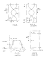
- detector 117 is advanced either clockwise or counterolockwise through a series of positions as indicated by arrows 209 .in FIG. 2a to gather information from many directions in a 360° oroit of the patient.
- the angular position of the detector is enccced to correlate with the emission data.
- the encoded position on the detector ana the signals provided by the scintillation camera are digitized and processed in a well-known manner by means of digital-computer apparatus. This information is then used to reconstruct the gathered data for display in a conventional visual image display device, such as a cathode-ray tuoe (not shown).
- a transmission-computed tomography apparatus such as that schematically depicted in FIG. 9 utilizing a fan-beam geometry will now be described.
- a body 901 undergoing examination is interposed between an X-ray source 903 and an array of X-ray detectors, generally designated 905, supported in a detector housing 907.
- the detector housing may, for example, be filled with an ionizaole gas, such as xenon, at a high pressure to increase the X-ray-stopping power thereof.
- X-ray source 903 typically includes a collimation means 909 which functions to confine the x-ray energy emanating from the source to a substantially planar, fan-shaped beam 911.
- a central sector of X-ray beam 911 irradiates body 901 and is transmitted therethrough to a group 913 of ionization chamber cells in the center of array 905.
- the angle of the X-ray fan beam is larger than the angle subtended by body 901 so that two peripheral sectors 915 of beam 911 are transmitted past the body without substantial attenuation to two groups of reference cells 917 at the periphery of the array.
- central group of cells 913 may, for example, comprise as many as 730 separate ionization detector cells, wnile each of the peripneral detector cell groups 917 may comprise a group of 6 independent cells.
- Eacn cell in the array is made up of a pair of positively charged anoce plates 919 and a negatively charged cathode plate 921 interposed therepetween forming an ionization chamber.
- X-ray photons entering the ionization chamber interact with the xenon gas and ionize it to produce electron/ion pairs.
- the positively charged ions are collected at signal electrodes 921 and incuce a signal current therein indicative of the X-ray intensity, wnile the electrons are collected at anodes 919.
- the electrical signal current obtained at each signal electrode 921 is produced precominantly by x-ray energy entering a single detector cell.
- the X-ray source and the detector array are caused, in one embodiment of scan geometries, to rotate jointly either clockwise or counterclockwise about the body, as suggested by arrows A and B in FIG. 9.
- the X-ray source and the detector array are mounted in-a gantry (not shown) and rotated jointly so as to obtain data from 3 6 0 0 .
- U .S. Patents 4,112,303 and 4,115,695 disclose details of gantry construction. A preferred embodiment of the detector array is disclosed in U .S.
- Patent 4 ,272,680 also assigned to the same assignee as the present invention. It should be noted that the method in accordance with the invention may be advantageously employed with other CT scan geometries sucn as that, for example, known to those skilled in the art as the "fourth generation.”
- the detector comprises a stationary annular structure which surrounds the object to be studied, while the radiation source is caused to orbit the object to obtain measurements from a plurality of projection angles.
- Signals from each detector cell in central group 913 and peripheral group of cells 917 in FIG. 9 are' applied by means of data-acquisition channels, such as those generally designated 923 to a data-acquisition means 925 which is of conventional design. From the data-acquisition means, the signals are applied for processing by a digital computer 927 to produce cross-sectional images of body 1 using techniques well known to the art and which will be described in greater detail hereinafter.
- the reconstructed images may be displayec on a cathode-ray tube monitor 929, for example.
- the signals provided by the peripheral detector cells 917 in response to excitation by unattenuated radiation from source 903 are utilized to compensate for variations in the intensity of X-ray source 903.
- Other uses for signals generated by the reference detector cells are disclosed and claimed in U.S. Patent Nos. 4,068,306 and 4,070,707, both assigned to the same assignee as the present invention.
- the data measured during a 360 0 scan of the object using one of the modalities described hereinbefore can be graonically displayed by means of sinogram such as that illustrated in FIG. 3,
- the horizontal axis cf the sinogram is the position along a projection, wnile the vertical axis corresponds to the angles of the measured projections (views).
- the value at eacn point in the ⁇ sinogram is the measured projection value.
- the point will trace a trajectory on the sinogram as it projects onto points nearer to the center of the detector and eventually onto the left side of the detector (FIG. 2b).
- the point will reverse direction and will terminate the trajectory at the starting point.
- the trajectory traced out is a sine wave for the parallel-beam-scan geometry.
- the sinusoid is slightly different for points situated in different locations in the object.
- the amplituce of the sine wave is determined by the distance of a point from the center of rotation while the pnase is determined by the angle that the line joining the point with the center of rotation makes when it intersects a reference direction, for example, the X-axis.
- the radioisotope density determines the amplitude of the measured readings (in the absence of noise) at the point where the point projects onto the detector.
- the sinogram is the superposition of tne sine waves for the indivicual points.
- a fan-beam sinogram is a display of the measured projections with the X-axis corresponding to the angle within a fan-beam projection and the vertical axis corresponding again to the angle of the projections.
- the trajectory of a point is no longer precisely a sine wave but looks very similar to a sinusoid. Since parallel-beam and fan-beam sinograms appear so similar to the eye, both will be described below with reference to FIG. 3.
- the sinogram in FIG. 3 shows a trajectory 301 of a point ooject.
- the trajectory begins at a position on the detector axis designated A 1 and terminates at a point A 2 wnich correspends to the same point on the axis.
- a 1 a position on the detector axis designated A 1
- a 2 wnich correspends to the same point on the axis.
- this coincidence is true only if point P remains stationary during the scan. If point P moves slowly curing the scan, then it will start at a point, for example, a 1 on the sinogram, out rather than ending at point 305 indicated along the lower horizontal axis in FIG. 3 (i.e., at the same position on the detector axis) it will end at a slightly different point B 2 .
- Point B 2 is offset from the starting position by a distance D.
- overscanning One known method used in transmission-computed tomography, for example, to reduce the effects of inconsistencies between the first and the last views is called overscanning.
- data is collected from a scan of the object which exceeds the normal 360 0 orbit.
- data may be collected for an additional 40°, that is, between 0° and 4 00 0 . This is illustrated on the sinogram depicted in FIG. 4.
- the data taken during the first 40° and for the last 4 0 0 of rotation should be redundant (except for measurement noise). In the presence of motion, they will differ and reflect the appearance of the object at the beginning and end of the scan time respectively.
- the old view 1 is weighted very little and view N v +1 has a much larger weight.
- the sum of the weight assigned to the views N v +1 and 1 should be unity as indicated on the vertical axis of FIG. 5.
- the resulting view is more similar to view N v (at 360 - > 3 degrees) than the original first view.
- views 2 and N v +2 are combined, the weight on view 2 is increased relative to the weight on view 1, while the weignt on view N v +2 is decreased. Again, the sum of the weights for view 2 and view N v +2 should be unity. This process is continued so that when views N and N v + N o are comoined, the old view, N , is weighed a lot and the resulting view is similar to view N o +1 which is not in the overscan region.
- the weights may be arranged in any suitable manner, provided the weight pairs for each view add to 1.
- FIGURE 5 illustrates several possibilities.
- the weights may be linear functions of view angle, as depicted by curve 501, or they may be cubic functions of angle as depicted by curve 503.
- Combining the weights in accordance with curve 503 is most effective in smoothing out the inconsistencies between the first and last views.
- the weignts may be arranged in a step-wise manner, as indicatec by curve 505.
- the advantage with curve 505 is that the views are essentially averaged, thereby improving the signal-to-noise ratio.
- Curves 501 and 503 are more effective than curve 505 in reducing motion-related artifacts; however, because the weights are unequal, the signal-to-noise ratio is somewhat lower for curves 501 and 503 than for curve 505. This is not a severe proolem, since in all of these the signal-to-noise ratios will be better than that cf the conventional non-overscan image.
- the distribution of weights in the overscan sinogram is shown in FIG. 6. Because of the overscan processing, especially if the weights increase anc decrease smoothly, any discrepancy due to motion is feathered out and the resulting image will contain fewer artifacts.
- underscan a method is disclosed herein, termed "underscan,” which has the apility to reduce motion artifacts utilizing the information in a normal 360° scan.
- underscan will cause the quantum noise content of the image to increase somewhat, thus reducing the dose efficiency, this penalty need not be paid all of the time, since the method can be applied retrospectively only when needed.
- the retrospective application of the method is possible since, in a typical system, the scan data can be electronically stored for later processing. Therefore, in the event that an image exhibits motion artifacts, the underscan method may be used to improve the quality of the image thus, in fact, making the scan more efficient.
- the underscan method can be most easily and simply understood with reference to a parallel-beam-scan geometry, such as that described by way of example with reference to FIG. 2a and with additional reference to FIG. 2b for the emission-tomograohy mocality.
- the underscan method recognizes that the 360° projection measurement data set already contains the required redundant information necessary to compensate for discontinuities between the first anc the last views.
- the views at the beginning and end of the scan still are processed with reduced weignts in order to achieve artifact reduction.
- this method it is not necessary to overscan to obtain the extra views necessary to compensate the reduced weight for the views having inconsistencies.
- parallel-ray geometry as seen in FIG.
- a ray at position r in one projection is duplicated in a position -r in the projection 180° away as seen in FIG. 2b, proviced that no motion or geometry errors nave occurred during the scan.
- the first view taken at 0 degrees and the last view, N v will contain inconsistencies which will result in streak artifacts in the direction of these projections.
- the first view is weighed by a small amount. In an overscan, an extra view was used to compensate for this reduced weight on view 1.
- the 360° parallel-ray data set already contains the required information in view 1 + (N v /2).
- the first view is assigned a weignt of W 1 and the mirror view, number 1 + N v , is assigned a weight of 2-W 1 .
- view N v receives a reduced weignt W v which can oe equal to W 1 to maintain symmetry and view N v receives a weight of 2-W v .
- the possible manner of arranging the weights is depicted graphically in FIG. 7 and by means of a sinogram in FIG. 8.
- the weights are typically increased monotonically toward 1 at the beginning of the scan for view angles between 0 and 8 0 , as indicated along the horizontal axis.
- the weights are reduced monotonically at the end of the scan between view angles of 360 0 - 8 o and 360°.
- Compensatory weights are applied to the views near the middle of the data set between view angles 180° - 8 and 180° + ⁇ 0 .
- the compensatory weights applied to views near the middle of the scan data set are needed in order to keep the compined weights of all pairs constant.
- Curves 701, 703, and 705 in FIG. 7 illustrate three exemplary arrangements which may be used for the weights in the underscan technique.
- Curve 701 is a linear function of view angle.
- Curve 703 depicts the use of cuoic functions of view angle for the regions where the weignts are not ecual to one and represents the preferred arrangement, since it has the greatest effectiveness of the three in reducing motion-related artifacts.
- Curve 705 shows the use of piecewise-constant weignts and is the least effective of the three in recuding motion artifacts.
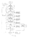
- FIGURE 10 is a simplified summary in flow-chart format of the processing steps in reconstructing an image from either parallel-ray or fan-beam projections. This sequence of steps is well known to those skilled in tomographic imaging. Additionally, FIG. 10 shows that the underscan weighting method in accordance with the present invention can be incorporated into the reconstruction process at preferably one of various positions. Generally, the reconstruction process includes preprocessing of the measured data which is then followed by image reconstruction by one of several available methods. In the preferred embodiment, backprojection of filtered projections is used. Filtering may be accomplished by a number of methods known to the art by, for examole, convolution or frequency space filtering using Fourier transformation.
- FIGURE 10 shows steps typical of those used for transmission tomography.
- i is the view index and reconstruction begins with preprocessing of the first view.
- Preprocessing begins with the steo of offset correction needed to compensate for the fact that even without any X-ray excitation there may be what is called a "dark current" produced in the detectors or electronics.
- the offset correction step eliminates this current by suotracting it.
- Gain compensation is necessitated by the fact thai each data channel, such as data-transmission channels 923 in FIG. 9, may nave different gain due to the unequal sensitivity of the detector cells themselves, or due to the electronic gain variations.
- the reference-normalization step is utilized to compensate for the fact that the X-ray beam intensity during any given view can vary.
- the normalization is performed by monitoring the X-ray beam intensity by means of one or more of the reference detector cells 917 depicted at the periphery of detector 907 in FIG. 9. Alternatively, the intensity of the X-ray source may be monitored cy detectors positioned near collimator 909. The method of the present invention can be inserted after this normalization steo.
- the method may alternatively be applied following the logarithmic-correction step which generally follows the normalization step in the pre-processing sequence of a transmission tomographic scanner.
- the method may alternatively be applied following the step of beam-hardening correction which follows the step of the logarithmic correction.
- the beam-hardening correction step is necessitated by the fact that X-ray are not monochromatic so that the lower energy x-rays are preferentially absorbed.
- the transmitted X-rays are richer in high energies and become more penetrating or "harder” so that a uniform material appears progressively less dense.
- Such hardening, if uncorrected, may introduce an artifact known as "cupping" in the reconstructed images.
- the beam-hardening step is followed by filtering, for example, by convolving the data with the convolution filter.
- the preprocessed data may be used as input to one of the alternate reconstruction methods.
- the filtered projection is backprojected. If weights that are uniform across projections are chosen, the method of the present invention may be inserted after the filtering step. This entire process is repeated for all views. If iterative reconstruction techniques are used, the various views are processed several times and are compared to calculated views produced from a brior estimate of the ooject. In this comparison any weighting applied to the jata must be taken into account, for examole, by comparing the weighted measured projections produced in accordance with the invention to similarly weigntea calculated projections:
- the first way the present invention can be applied to fan-beam-scan geometry is to use the underscan method with the methods of reordering and rebinning, as described, for example, in U.S. Patent No. 4,075, 492 issued to Boyd et al, which is assigned to the same assignee as the present invention and which is incorporated herein by reference.
- the methods of reordering and repinning are used to produce a set of parallel-ray projections from the fan-oeam projections. These methods rely on the fact that, while the measurements within a fan-beam projection are not along parallel rays, proper sorting of fan-beam projections can produce sets of measurements along rays that are nearly parallel.
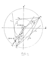
- the measurements p(8, ⁇ ) and p(8', ⁇ + 8 - 8') are line integrals made along parallel lines.
- the radiation source is positioned at a point S 1 .
- G 1 the central ray of the fan beam, i.e., the ray that passes through the center of rotation 0 which is the origin of the coordinate system, forms an angie 8 with respect to the negative Y-axis.
- the limits of the fan beam are defined by the rays E 1 and F 1 which are tangent to the scan field of view A.
- R be a ray of interest within this fan beam.
- FIG. 11 shows a second fan beam formed when the source is in position S 2 .
- the peripneral rays of the oeam at S 2 are not shown to preserve clarity in FIG. 11.
- This second fan peam is at an angle 8' with respect to the negative Y-axis.
- ray R' within the second fan beam is parallel to ray R.
- the angle of R' with respect to the central ray G 2 of the fan beam to which it belongs is ( ⁇ + 8 - 9').
- One complicating factor in these reordering methods is that the measurements are generally not made continuously but are discrete in both 8 and ⁇ .
- the line integral along R is measured twice; once when the source is at S 1 where the view angle is 8 degrees and the ray angle is ⁇ degrees, and again wnen the source is at S 3 where the view angle is 8+18C+20 degrees and the ray angle is - ⁇ derress.
- G 3 is the central ray of the fan beam produced wnen the source is at S 3 and E 3 and F 3 are the limits of this fan beam.
- This property of the fan-oeam geometry can be used to produce artificial fan-beam projections as described, for example, in U.S. Patent No. 4,280,178, assigned to the same assignee as the present invention and which is incorporated herein by reference.
- the process is referred to as reflection and is analogous to reordering fan beam projections into parallel-ray projections except that the output projections are also of the fan-ceam type
- This method of creating artificial projections can be used with the motion artifact reducing underscan method described above and applied to fan-beam applications. using reflection the fan-beam projections near the middle of the scan are used to produce new fan-beam projections for the angles near the beginning and the end of the scan.
- a somewhat better approach is to use reflection to generate views that correspond in angle with both the beginning and the end of the scan.
- p(8, ⁇ ) be the measured fan-beam view at angle 8 and p.
- (8, ⁇ ) be the artificial view generated using reflection for this angular position.
- Artificial views can be calculated for the angular range from 0 to 8 0 degrees and from (360-8 o ) to 360 degrees. values of between 30 and 60 degrees could be used for 8 0 , for example.
- the original views can be combined with the artificial views by: where W(8, ⁇ ) is the weight acclied to the original view at angle 9, and ô( ⁇ , ) is the outout view resulting from the comoination.
- the image wculc be reconstructed using these output views in the angular regions for wnicn artificial views are calculated and using the original measured views outside these regions.
- the weights are constant along fan-beam projections, the weights could be chosen to not be constant along one fan beam projection. As was described aoove, in order to reduce motion artifacts, it is desirable to use reduced weights for the original views near the beginning and the end of the scan.
- the preferred approach is to use a very small weight for the first original view while the corresponding artificial view receives a much larger weight, and to increase the weight on the original views smoothly until at angle 8 o the weight on the original view is nearly the nominal weight.
- the weights on the artificial views would decrease in a similar manner. Weights for the original views that increase with angle in a linear, cubic or some other fashion can be used. The weights would be arranged analogously at the end of the scan. The original view at angle (360-8 0 ) would receive almost the full nominal weight while the artificial view at this angle receives a very small weight.
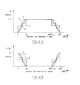
- FIGS. 12a and 12b illustrate, respectively, several possible weight distribution configurations for the original views and the corresponding weights for the artificial views.
- the weights vary smoothly with angle (curves 0, 0', P and P', FIGS. 12a and 12b)
- the use of weights that vary in a step-wise manner is shown (curves Q, Q', R and R', FIGS.
- FIGURE 13 shows in flow-chart format the majxr data processing steps involved in the embodiment using reflection. Processing oegins with view 1.
- the projection data is preprocessed as described with reference to FIG. 10. Some or all of the preprocessing steps described in FIG. 10 may be incluced at this point in FIG. 13.
- an artificial view is calculated using similarly preprocessea data from tne middle of the scan, and the artificial and measured views are combined.
- the output view, or the measured view for the view angles that are uneffected, is then subjected to any remaining preprocessing steps. Following this, the view is processed in the standard way by the filtered backprojection or other reconstruction algorithm. The process continues until all view angles have been treated.
- sorting, reordering or rebinning were used essentially to reorganize the availaole data in sucn a way that the weighting can be accomplished readily.
- FIGURE 14 snows the distribution of weights in a fan-beam sincgram. It can be seen that the weights are less than the nominal weight for the views between 0 ane 8 o degrees (region I), are equal to the nominal weight for a wnile (region II), are higher than the nominal weight in a diagonal swath of the sinogram (region III), are again equal to the nominal weight in region IV, and are lower than the nominal weight at the end of the scan (region V). Note that the allowed values of 8 o are limited oy the fact that if 8 o is too large regions I and III will overlap. In particular, 8 o must satisfy where ⁇ max degrees is the largest divergence of the fan beam from the central ray (i.e., ⁇ max is equal to one half of the full fan angle).
- weights may be better understood by examining one particular case in more detail, for example, the use of weights that increase as cubic functions of angle and are constant over fan-beam views at the beginning of the scan. Assume that it is desired to have the weights be zero for the view measured at 0 degrees, have zero slope at this angle, and increase to a value of one at an angle of ⁇ o where they again have zero slope. This is given by:
- the weights in the middle of the scan are: where x 9-180+2 (12) ⁇ o and indicates absolute value.
- N v fan-beam projections uniformly spaced over 360 degrees have been acquired.
- the range of angles over whicn the weignts on the views at the ceginning of the scan will receive orogressively increasing weights is specified by choosing to be a certain number of views, say N u .
- wnere c is the index, including any fractional part, corresponding to the point in the fan beam onto whicn the central ray projects.
- the flow chart on FIG. 10 applies equally well for fan-beam application as for the parallel-beam case. The only difference is that the weighting process in accordance with the invention in the fan-beam case is best implemented before the filtering step.
- the weighting process for fan-beam applications can be summarized (for the present example of cubic weights and equally spacec samples within a substantially symmetric fan beam) by the following sequence of steps:
- weights that are uniform across the fan-beam projections at the beginning and end of the scan were used. This property is ideal for uniform suppression of artifacts.
- other weignts could be used.
- constant weights may be used for rays that are substantially parallel. That is, the weignt applied to a ray depends on the aosolute angle of the ray to a different direction. This is equivalent to resinning into parallel rays, weighing the parallel data set, and reoinning back to fan-beam projections. In this case, the weights are never constant along fan-beam projection. It should be unoerstood that other weignts can also be chosen.
- the common property is that, to reduce motion artifacts, the weignts must be less than 1 for the views near the beginning and enc of the scan.
- a method for reducing the effects of moti-related or scanner-geometry-aberrration-related artifacts in images reconstructed from projections having inconsistencies between the first and last views, cue to the fact that the ooject has moved during the scan interval or the scanner nas not perfectly executed its motion.
- the methoc is effective in reducing such artifacts independent of the modality used to cbtain the projections.
- the method is applicable to projections ootained in emission-nuclear tomograpny, computerized tomography, ultrasound, and nuclear magnetic resonance studies.
- the technique in accordance with the invention is effective in recucing motion artifacts oy utilizing information contained in normal 360° scans of the object.
- this method it is possible to use this method to produce an image when the scan covers somewnat less than 360 0 .
- a scan that covers 330 degrees, say from 15 degrees to 345 degrees and compare it to a full 360-degree scan.
- the full scan had been procesed using the above-described method where, in particular, the views from 0 to 15° anc the views from 345° to 360° received zero weight and where the weights for the views near the middle of the scan comcensated for this.
- apply these weignts to the 330-degree scan. Since the missing views would receive dc wieght, they will not be missed.
Landscapes
- Life Sciences & Earth Sciences (AREA)
- Engineering & Computer Science (AREA)
- Health & Medical Sciences (AREA)
- Physics & Mathematics (AREA)
- Medical Informatics (AREA)
- Radiology & Medical Imaging (AREA)
- Heart & Thoracic Surgery (AREA)
- High Energy & Nuclear Physics (AREA)
- Theoretical Computer Science (AREA)
- Nuclear Medicine, Radiotherapy & Molecular Imaging (AREA)
- Optics & Photonics (AREA)
- Pathology (AREA)
- General Physics & Mathematics (AREA)
- Biomedical Technology (AREA)
- Biophysics (AREA)
- Molecular Biology (AREA)
- Surgery (AREA)
- Animal Behavior & Ethology (AREA)
- General Health & Medical Sciences (AREA)
- Public Health (AREA)
- Veterinary Medicine (AREA)
- Apparatus For Radiation Diagnosis (AREA)
- Nuclear Medicine (AREA)
- Ultra Sonic Daignosis Equipment (AREA)
- Analysing Materials By The Use Of Radiation (AREA)
Applications Claiming Priority (2)
| Application Number | Priority Date | Filing Date | Title |
|---|---|---|---|
| US06/490,604 US4580219A (en) | 1983-05-02 | 1983-05-02 | Method for reducing image artifacts due to projection measurement inconsistencies |
| US490604 | 1983-05-02 |
Publications (3)
| Publication Number | Publication Date |
|---|---|
| EP0124015A2 true EP0124015A2 (de) | 1984-11-07 |
| EP0124015A3 EP0124015A3 (en) | 1987-05-13 |
| EP0124015B1 EP0124015B1 (de) | 1991-01-30 |
Family
ID=23948750
Family Applications (1)
| Application Number | Title | Priority Date | Filing Date |
|---|---|---|---|
| EP84104342A Expired - Lifetime EP0124015B1 (de) | 1983-05-02 | 1984-04-17 | Verfahren und Vorrichtung zur Reduzierung von Bildartefakten wegen Unbeständigkeit der Projektionsmessung |
Country Status (5)
| Country | Link |
|---|---|
| US (1) | US4580219A (de) |
| EP (1) | EP0124015B1 (de) |
| JP (1) | JPS605127A (de) |
| DE (1) | DE3484026D1 (de) |
| IL (1) | IL71092A (de) |
Cited By (5)
| Publication number | Priority date | Publication date | Assignee | Title |
|---|---|---|---|---|
| EP0235302A4 (de) * | 1985-08-30 | 1989-03-29 | Yokogawa Medical Syst | Datensammelverfahren für röntgenstrahltomographen. |
| EP0428348A3 (en) * | 1989-11-13 | 1992-07-01 | General Electric Company | Helical scanning computed tomography |
| EP0713678A1 (de) * | 1994-11-25 | 1996-05-29 | Picker International, Inc. | Abbildungsverfahren und entsprechende Vorrichtung |
| WO2010109352A1 (en) * | 2009-03-26 | 2010-09-30 | Koninklijke Philips Electronics N.V. | Method and apparatus for computed tomography image reconstruction |
| CN112904743A (zh) * | 2021-01-20 | 2021-06-04 | 清华大学 | 一种用于计算刚性电力电子系统的离散状态事件驱动的方法 |
Families Citing this family (91)
| Publication number | Priority date | Publication date | Assignee | Title |
|---|---|---|---|---|
| JPS60111640A (ja) * | 1983-11-21 | 1985-06-18 | 横河メディカルシステム株式会社 | 画像再構成装置 |
| US4718010A (en) * | 1984-12-28 | 1988-01-05 | Kabushiki Kaisha Toshiba | CT system for creating image data from high and low energy radiation |
| GB2181330B (en) * | 1985-09-26 | 1990-05-09 | Toshiba Kk | X-ray inspection apparatus |
| US4858128A (en) * | 1986-08-11 | 1989-08-15 | General Electric Company | View-to-view image correction for object motion |
| JPS63255042A (ja) * | 1987-04-10 | 1988-10-21 | 株式会社東芝 | Ct装置におけるデ−タ収集方式 |
| US4879652A (en) * | 1987-09-04 | 1989-11-07 | General Electric Company | Method for producing three-dimensional images from nuclear data |
| US4994965A (en) * | 1988-11-23 | 1991-02-19 | General Electric Company | Method for reducing motion induced image artifacts in projection imaging |
| JPH0616099B2 (ja) * | 1989-02-07 | 1994-03-02 | 浜松ホトニクス株式会社 | Ct装置におけるデータ補正装置 |
| US5128864A (en) * | 1989-08-09 | 1992-07-07 | W. L. Systems, Inc. | Method for computing tomographic scans |
| US5051903A (en) * | 1989-08-14 | 1991-09-24 | General Electric Company | Method and apparatus for predicting values of a varying periodic phenomenon |
| US5170346A (en) * | 1989-11-22 | 1992-12-08 | General Electric Company | Method for reducing patient translation artifacts in tomographic imaging |
| JP3089050B2 (ja) * | 1991-06-19 | 2000-09-18 | 株式会社東芝 | Spect画像の再構成方法 |
| US5273041A (en) * | 1992-04-30 | 1993-12-28 | General Electric Company | Fiber optic photoplethysmograph for a magnetic resonance imaging system |
| DE4334937A1 (de) * | 1993-10-13 | 1995-10-05 | Siemens Ag | Computertomograph |
| US5406479A (en) * | 1993-12-20 | 1995-04-11 | Imatron, Inc. | Method for rebinning and for correcting cone beam error in a fan beam computed tomographic scanner system |
| US5491735A (en) * | 1994-12-22 | 1996-02-13 | General Electric Company | Image reconstruction apparatus and method for helical scanning |
| US5513236A (en) * | 1995-01-23 | 1996-04-30 | General Electric Company | Image reconstruction for a CT system implementing a dual fan beam helical scan |
| US5575286A (en) * | 1995-03-31 | 1996-11-19 | Siemens Medical Systems, Inc. | Method and apparatus for generating large compound ultrasound image |
| JP3583503B2 (ja) * | 1995-04-13 | 2004-11-04 | 株式会社日立メディコ | 医療用診断ct装置 |
| US5541970A (en) * | 1995-05-09 | 1996-07-30 | General Electric Company | Image reconstruction for a CT system implementing a four fan beam helical scan |
| US6065475A (en) * | 1995-06-08 | 2000-05-23 | Siemens Corporate Research, Inc. | Automatic localization of the heart from a reconstructed volume and automatic selection of a most suitable representative transverse slice for defining a left ventricle oblique axis in myocardial spect study |
| US5546439A (en) * | 1995-11-02 | 1996-08-13 | General Electric Company | Systems, methods and apparatus for incrementally reconstructing overlapped images in a CT system implementing a helical scan |
| US5559847A (en) * | 1995-12-06 | 1996-09-24 | General Electric Company | Systems, methods and apparatus for reconstructing images in a CT system implementing a helical scan |
| US5606585A (en) * | 1995-12-21 | 1997-02-25 | General Electric Company | Methods and apparatus for multislice helical image reconstruction in a computer tomography system |
| AU1983397A (en) * | 1996-02-29 | 1997-09-16 | Acuson Corporation | Multiple ultrasound image registration system, method and transducer |
| US5663995A (en) * | 1996-06-06 | 1997-09-02 | General Electric Company | Systems and methods for reconstructing an image in a CT system performing a cone beam helical scan |
| US5873830A (en) * | 1997-08-22 | 1999-02-23 | Acuson Corporation | Ultrasound imaging system and method for improving resolution and operation |
| US6078639A (en) * | 1997-11-26 | 2000-06-20 | Picker International, Inc. | Real time continuous CT imaging |
| US6373060B1 (en) * | 1998-01-30 | 2002-04-16 | Kabushiki Kaisha Toshiba | Nuclear medicine diagnostic apparatus |
| US6456394B1 (en) * | 1998-12-10 | 2002-09-24 | Xerox Corporation | Method for reducing halo print defects associated with color images |
| US6701000B1 (en) * | 1999-04-30 | 2004-03-02 | General Electric Company | Solution to detector lag problem in a solid state detector |
| US6351548B1 (en) * | 1999-06-23 | 2002-02-26 | The Board Of Trustees Of The University Of Illinois | Fast hierarchical reprojection algorithm for tomography |
| US6535084B1 (en) | 2000-01-15 | 2003-03-18 | Ge Medical Systems Global Technology Company, Llc | Method and apparatus for designing an RF coil assembly |
| US6381297B1 (en) | 2000-08-15 | 2002-04-30 | Ge Medical Systems Global Technology Company, Llc | High pitch reconstruction of multislice CT scans |
| US6707879B2 (en) | 2001-04-03 | 2004-03-16 | L-3 Communications Security And Detection Systems | Remote baggage screening system, software and method |
| JP4607364B2 (ja) * | 2001-04-04 | 2011-01-05 | ジーイー・メディカル・システムズ・グローバル・テクノロジー・カンパニー・エルエルシー | X線ct装置 |
| US20060274916A1 (en) * | 2001-10-01 | 2006-12-07 | L-3 Communications Security And Detection Systems | Remote data access |
| US20060115109A1 (en) * | 2001-10-01 | 2006-06-01 | L-3 Communications Security And Detection Systems, Inc. | Ensuring airline safety while safeguarding personal passenger information |
| US8031903B2 (en) * | 2001-10-01 | 2011-10-04 | L-3 Communications Security And Detection Systems, Inc. | Networked security system |
| US20030085163A1 (en) * | 2001-10-01 | 2003-05-08 | Chan Chin F. | Remote data access |
| US20030072478A1 (en) * | 2001-10-12 | 2003-04-17 | Claus Bernhard Erich Hermann | Reconstruction method for tomosynthesis |
| US6816571B2 (en) | 2002-02-06 | 2004-11-09 | L-3 Communications Security And Detection Systems Corporation Delaware | Method and apparatus for transmitting information about a target object between a prescanner and a CT scanner |
| JP2007527253A (ja) * | 2003-02-14 | 2007-09-27 | コーニンクレッカ フィリップス エレクトロニクス エヌ ヴィ | 冗長データを含むヘリカルコーンビーム・コンピュータ断層撮像法に対する正確な画像再構成システム及び方法 |
| US6931094B2 (en) * | 2003-10-10 | 2005-08-16 | Ge Medical Systems Global Technology Company, Llc | Methods and systems for smoothing |
| EP1689640A2 (de) * | 2003-11-19 | 2006-08-16 | L-3 Communications Security and Detection Systems Corporation | Sicherheitssystem mit verteilter berechnung |
| JP4646810B2 (ja) * | 2004-02-16 | 2011-03-09 | 株式会社日立メディコ | 断層撮影像の再構成方法及び断層撮影装置 |
| WO2005082009A2 (en) * | 2004-02-25 | 2005-09-09 | Digirad Corporation | Small field-of-view detector head ('spect') attenuation correction system |
| US6996206B2 (en) * | 2004-04-12 | 2006-02-07 | General Electric Company | Method, system and storage medium for reference normalization for blocked reference channels |
| JP2006000225A (ja) * | 2004-06-15 | 2006-01-05 | Canon Inc | X線ct装置 |
| EP1765174A1 (de) * | 2004-07-07 | 2007-03-28 | Koninklijke Philips Electronics N.V. | Streifenartefakt-verringerung in der kardialen kegelstrahl-ct-rekonstruktion |
| US7711170B2 (en) * | 2005-05-10 | 2010-05-04 | General Electric Company | Method and system for filtering scan data |
| JP2009503544A (ja) * | 2005-08-01 | 2009-01-29 | バイオプティジェン,インコーポレイテッド | 試料から取得された3次元データセットを解析する方法、システム及びコンピュータ・プログラムプロダクト |
| US7283605B2 (en) * | 2006-01-14 | 2007-10-16 | General Electric Company | Methods and apparatus for scatter correction |
| US7620309B2 (en) * | 2006-04-04 | 2009-11-17 | Adobe Systems, Incorporated | Plenoptic camera |
| JP5572386B2 (ja) * | 2006-10-18 | 2014-08-13 | コーニンクレッカ フィリップス エヌ ヴェ | 関心領域を撮像する撮像システム、撮像方法及びコンピュータプログラム |
| US8218720B2 (en) * | 2007-03-12 | 2012-07-10 | Varian Medical Systems, Inc. | Method and apparatus to facilitate reconstructing an image using fan-beam data |
| US20080273651A1 (en) * | 2007-05-05 | 2008-11-06 | Franz Edward Boas | Methods and apparatus for reducing artifacts in computed tomography images |
| US8290358B1 (en) | 2007-06-25 | 2012-10-16 | Adobe Systems Incorporated | Methods and apparatus for light-field imaging |
| US8019215B2 (en) * | 2007-08-06 | 2011-09-13 | Adobe Systems Incorporated | Method and apparatus for radiance capture by multiplexing in the frequency domain |
| JP5179136B2 (ja) * | 2007-10-02 | 2013-04-10 | ジーイー・メディカル・システムズ・グローバル・テクノロジー・カンパニー・エルエルシー | X線ct装置 |
| US8189065B2 (en) | 2008-01-23 | 2012-05-29 | Adobe Systems Incorporated | Methods and apparatus for full-resolution light-field capture and rendering |
| US7962033B2 (en) | 2008-01-23 | 2011-06-14 | Adobe Systems Incorporated | Methods and apparatus for full-resolution light-field capture and rendering |
| US8155456B2 (en) * | 2008-04-29 | 2012-04-10 | Adobe Systems Incorporated | Method and apparatus for block-based compression of light-field images |
| US8244058B1 (en) | 2008-05-30 | 2012-08-14 | Adobe Systems Incorporated | Method and apparatus for managing artifacts in frequency domain processing of light-field images |
| US8938104B2 (en) * | 2008-08-29 | 2015-01-20 | Varian Medical Systems International Ag | Systems and methods for adaptive filtering |
| US8189089B1 (en) | 2009-01-20 | 2012-05-29 | Adobe Systems Incorporated | Methods and apparatus for reducing plenoptic camera artifacts |
| US8315476B1 (en) | 2009-01-20 | 2012-11-20 | Adobe Systems Incorporated | Super-resolution with the focused plenoptic camera |
| US8345144B1 (en) | 2009-07-15 | 2013-01-01 | Adobe Systems Incorporated | Methods and apparatus for rich image capture with focused plenoptic cameras |
| US8228417B1 (en) | 2009-07-15 | 2012-07-24 | Adobe Systems Incorporated | Focused plenoptic camera employing different apertures or filtering at different microlenses |
| US8400555B1 (en) | 2009-12-01 | 2013-03-19 | Adobe Systems Incorporated | Focused plenoptic camera employing microlenses with different focal lengths |
| US8817015B2 (en) | 2010-03-03 | 2014-08-26 | Adobe Systems Incorporated | Methods, apparatus, and computer-readable storage media for depth-based rendering of focused plenoptic camera data |
| US8744159B2 (en) * | 2010-03-05 | 2014-06-03 | Bioptigen, Inc. | Methods, systems and computer program products for collapsing volume data to lower dimensional representations thereof using histogram projection |
| US8358366B1 (en) | 2010-05-28 | 2013-01-22 | Adobe Systems Incorporate | Methods and apparatus for high-speed digital imaging |
| US8749694B2 (en) | 2010-08-27 | 2014-06-10 | Adobe Systems Incorporated | Methods and apparatus for rendering focused plenoptic camera data using super-resolved demosaicing |
| US8724000B2 (en) | 2010-08-27 | 2014-05-13 | Adobe Systems Incorporated | Methods and apparatus for super-resolution in integral photography |
| US8803918B2 (en) | 2010-08-27 | 2014-08-12 | Adobe Systems Incorporated | Methods and apparatus for calibrating focused plenoptic camera data |
| US8665341B2 (en) | 2010-08-27 | 2014-03-04 | Adobe Systems Incorporated | Methods and apparatus for rendering output images with simulated artistic effects from focused plenoptic camera data |
| WO2012056379A1 (en) * | 2010-10-27 | 2012-05-03 | Koninklijke Philips Electronics N.V. | Image artifact identification and mitigation |
| US9030550B2 (en) | 2011-03-25 | 2015-05-12 | Adobe Systems Incorporated | Thin plenoptic cameras using solid immersion lenses |
| US9177397B2 (en) * | 2011-06-21 | 2015-11-03 | Koninklijke Philips N.V. | Imaging apparatus |
| CA3069211C (en) | 2011-09-07 | 2022-06-21 | Rapiscan Systems, Inc. | X-ray inspection system that integrates manifest data with imaging/detection processing |
| US9377291B2 (en) | 2013-12-05 | 2016-06-28 | Bioptigen, Inc. | Image registration, averaging, and compounding for high speed extended depth optical coherence tomography |
| WO2016033590A1 (en) | 2014-08-31 | 2016-03-03 | Berestka John | Systems and methods for analyzing the eye |
| US9466134B2 (en) | 2014-12-18 | 2016-10-11 | General Electric Company | Systems and methods for motion correction using magnetic resonance imaging information |
| US10524756B2 (en) * | 2015-08-27 | 2020-01-07 | Varian Medical Systems International | Methods and systems for image artifacts reduction |
| US20180211423A1 (en) * | 2015-10-28 | 2018-07-26 | Koninklijke Philips N.V. | Computed tomography image generation apparatus |
| PL3764280T3 (pl) | 2016-02-22 | 2025-03-17 | Rapiscan Systems, Inc. | Sposoby weryfikacji typów kontenerów |
| JP6062589B1 (ja) * | 2016-04-28 | 2017-01-18 | 株式会社Live2D | プログラム、情報処理装置、影響度導出方法、画像生成方法及び記録媒体 |
| EP3413033B1 (de) * | 2017-06-09 | 2020-09-23 | Roche Diagnostics GmbH | Verfahren und vorrichtung zur bestimmung der eigenschaften einer laborprobe in einem laborprobenbehälter |
| CN115005860B (zh) * | 2022-08-03 | 2022-11-15 | 有方(合肥)医疗科技有限公司 | 一种减少口腔颌面cbct成像运动伪影的方法及装置 |
| GB2635586A (en) | 2023-11-07 | 2025-05-21 | Lightfield Medical Inc | Systems and methods for analyzing the eye |
Family Cites Families (20)
| Publication number | Priority date | Publication date | Assignee | Title |
|---|---|---|---|---|
| US3011057A (en) * | 1958-01-02 | 1961-11-28 | Hal O Anger | Radiation image device |
| GB1493243A (en) * | 1974-02-15 | 1977-11-30 | Emi Ltd | Radiographic apparatus |
| FR2284306A1 (fr) * | 1974-09-13 | 1976-04-09 | Thomson Csf | Perfectionnements aux appareils de visualisation d'une section d'un corps soumis a des radiations penetrantes, et notamment a des rayonx x ou g |
| US4075492A (en) * | 1974-11-29 | 1978-02-21 | The Board Of Trustees Of Leland Stanford Junior University | Fan beam X- or γ-ray 3-D tomography |
| US4433380A (en) * | 1975-11-25 | 1984-02-21 | Philips Medical Systems, Inc. | Tomographic scanner |
| US4068306A (en) * | 1976-07-12 | 1978-01-10 | General Electric Co. | X-ray data acquisition system and method for calibration |
| US4070707A (en) * | 1976-07-12 | 1978-01-24 | General Electric Company | Reduction of offsets in data acquisition systems |
| US4112303A (en) * | 1977-02-25 | 1978-09-05 | General Electric Company | Gantry for computed tomography |
| US4115695A (en) * | 1977-02-25 | 1978-09-19 | General Electric Company | Gantry for computed tomography |
| US4115696A (en) * | 1977-04-18 | 1978-09-19 | General Electric Company | Computed tomography scanner |
| DE2754361C2 (de) * | 1977-12-07 | 1983-07-14 | N.V. Philips' Gloeilampenfabrieken, 5621 Eindhoven | Verfahren zur Verminderung von Bildfehlern in Computer-Tomographiebildern |
| US4217641A (en) * | 1978-04-28 | 1980-08-12 | U.S. Philips Corporation | Correction for polychromatic X-ray distortion in CT images |
| GB1602071A (en) * | 1978-05-12 | 1981-11-04 | Emi Ltd | Processing arrangements for medical examination |
| EP0010885B1 (de) * | 1978-10-24 | 1983-02-23 | EMI Limited | Gerät für Computer-Tomographie |
| US4216381A (en) * | 1979-05-10 | 1980-08-05 | General Electric Company | Structure for emission tomography scintillation camera |
| US4280178A (en) * | 1979-08-24 | 1981-07-21 | General Electric Company | Computerized tomographic reconstruction method utilizing reflection |
| US4418387A (en) * | 1979-09-18 | 1983-11-29 | The President Of Tokyo Institute Of Technology | Method of reconstructing a computed tomographic image from a single X-ray projection |
| US4272680A (en) * | 1979-12-03 | 1981-06-09 | General Electric Company | Modular array radiation detector |
| JPS6058504B2 (ja) * | 1980-11-17 | 1985-12-20 | 株式会社東芝 | 再構成装置 |
| US4463375A (en) * | 1982-09-07 | 1984-07-31 | The Board Of Trustees Of The Leland Standford Junior University | Multiple-measurement noise-reducing system |
-
1983
- 1983-05-02 US US06/490,604 patent/US4580219A/en not_active Expired - Lifetime
-
1984
- 1984-02-28 IL IL71092A patent/IL71092A/xx not_active IP Right Cessation
- 1984-04-17 DE DE8484104342T patent/DE3484026D1/de not_active Expired - Lifetime
- 1984-04-17 EP EP84104342A patent/EP0124015B1/de not_active Expired - Lifetime
- 1984-05-02 JP JP59087946A patent/JPS605127A/ja active Granted
Cited By (6)
| Publication number | Priority date | Publication date | Assignee | Title |
|---|---|---|---|---|
| EP0235302A4 (de) * | 1985-08-30 | 1989-03-29 | Yokogawa Medical Syst | Datensammelverfahren für röntgenstrahltomographen. |
| EP0428348A3 (en) * | 1989-11-13 | 1992-07-01 | General Electric Company | Helical scanning computed tomography |
| EP0713678A1 (de) * | 1994-11-25 | 1996-05-29 | Picker International, Inc. | Abbildungsverfahren und entsprechende Vorrichtung |
| WO2010109352A1 (en) * | 2009-03-26 | 2010-09-30 | Koninklijke Philips Electronics N.V. | Method and apparatus for computed tomography image reconstruction |
| US8787646B2 (en) | 2009-03-26 | 2014-07-22 | Koninklijke Philips N.V. | Method and apparatus for computed tomography image reconstruction |
| CN112904743A (zh) * | 2021-01-20 | 2021-06-04 | 清华大学 | 一种用于计算刚性电力电子系统的离散状态事件驱动的方法 |
Also Published As
| Publication number | Publication date |
|---|---|
| DE3484026D1 (de) | 1991-03-07 |
| JPS605127A (ja) | 1985-01-11 |
| JPH0442011B2 (de) | 1992-07-10 |
| US4580219A (en) | 1986-04-01 |
| EP0124015A3 (en) | 1987-05-13 |
| IL71092A0 (en) | 1984-05-31 |
| IL71092A (en) | 1988-11-30 |
| EP0124015B1 (de) | 1991-01-30 |
Similar Documents
| Publication | Publication Date | Title |
|---|---|---|
| EP0124015B1 (de) | Verfahren und Vorrichtung zur Reduzierung von Bildartefakten wegen Unbeständigkeit der Projektionsmessung | |
| Hogan et al. | Fluorescent computer tomography: a model for correction of X-ray absorption | |
| Jaszczak et al. | Whole-body single-photon emission computed tomography using dual, large-field-of-view scintillation cameras | |
| US5128864A (en) | Method for computing tomographic scans | |
| US6665370B2 (en) | Computed tomography method and apparatus for acquiring images dependent on a time curve of a periodic motion of the subject | |
| Cherry et al. | Correction and characterization of scattered events in three-dimensional PET using scanners with retractable septa | |
| US3927318A (en) | Cross-sectional fluorescent imaging system | |
| Brix et al. | Performance evaluation of a whole-body PET scanner using the NEMA protocol | |
| US5293312A (en) | Method and apparatus for computing tomographic scans | |
| EP2693949B1 (de) | Adaptive kalibrierung für tomografische abbildungssysteme | |
| US6408049B1 (en) | Apparatus, methods, and computer programs for estimating and correcting scatter in digital radiographic and tomographic imaging | |
| US6256365B1 (en) | Apparatus and method for reconstruction of images in a computed tomography system using oblique slices | |
| US6658081B2 (en) | Computed tomography method and apparatus for optimized detector utilization and dose utilization | |
| US4984159A (en) | Method and apparatus for estimating elliptical body contours in fan beam computed tomographic systems | |
| US6429433B1 (en) | Continuous rotation sampling scheme for transmission radiation corrected gamma cameras | |
| US5323007A (en) | Method of recovering tomographic signal elements in a projection profile or image by solving linear equations | |
| US6539103B1 (en) | Method and apparatus for image reconstruction using a knowledge set | |
| GULLBERG et al. | Cone beam tomography of the heart using single-photon emission-computed tomography | |
| EP0608237B1 (de) | Verfahren und vorrichtung für computerisierte tomographie- und panorama abtastungen | |
| US7323689B2 (en) | Attenuation correction in nuclear medicine studies by simultaneous transmission and emission data measurement and estimation of emission-to-transmission crosstalk | |
| Greer et al. | An overview of a camera‐based SPECT system | |
| Gullberg et al. | An iterative reconstruction algorithm for single photon emission computed tomography with cone beam geometry | |
| Li et al. | A cone beam SPECT reconstruction algorithm with a displaced center of rotation | |
| Onishi et al. | Differential impact of multi-focus fan beam collimation with L-mode and conventional systems on the accuracy of myocardial perfusion imaging: Quantitative evaluation using phantoms | |
| Digby et al. | An investigation of scatter in attenuation correction for PET |
Legal Events
| Date | Code | Title | Description |
|---|---|---|---|
| PUAI | Public reference made under article 153(3) epc to a published international application that has entered the european phase |
Free format text: ORIGINAL CODE: 0009012 |
|
| AK | Designated contracting states |
Designated state(s): DE FR GB NL |
|
| PUAL | Search report despatched |
Free format text: ORIGINAL CODE: 0009013 |
|
| AK | Designated contracting states |
Kind code of ref document: A3 Designated state(s): DE FR GB NL |
|
| 17P | Request for examination filed |
Effective date: 19871016 |
|
| 17Q | First examination report despatched |
Effective date: 19890602 |
|
| GRAA | (expected) grant |
Free format text: ORIGINAL CODE: 0009210 |
|
| AK | Designated contracting states |
Kind code of ref document: B1 Designated state(s): DE FR GB NL |
|
| ET | Fr: translation filed | ||
| REF | Corresponds to: |
Ref document number: 3484026 Country of ref document: DE Date of ref document: 19910307 |
|
| PLBE | No opposition filed within time limit |
Free format text: ORIGINAL CODE: 0009261 |
|
| STAA | Information on the status of an ep patent application or granted ep patent |
Free format text: STATUS: NO OPPOSITION FILED WITHIN TIME LIMIT |
|
| 26N | No opposition filed | ||
| PGFP | Annual fee paid to national office [announced via postgrant information from national office to epo] |
Ref country code: FR Payment date: 19920312 Year of fee payment: 9 |
|
| PGFP | Annual fee paid to national office [announced via postgrant information from national office to epo] |
Ref country code: GB Payment date: 19920317 Year of fee payment: 9 |
|
| PG25 | Lapsed in a contracting state [announced via postgrant information from national office to epo] |
Ref country code: GB Effective date: 19930417 |
|
| GBPC | Gb: european patent ceased through non-payment of renewal fee |
Effective date: 19930417 |
|
| PG25 | Lapsed in a contracting state [announced via postgrant information from national office to epo] |
Ref country code: FR Effective date: 19931229 |
|
| REG | Reference to a national code |
Ref country code: FR Ref legal event code: ST |
|
| PGFP | Annual fee paid to national office [announced via postgrant information from national office to epo] |
Ref country code: NL Payment date: 19950430 Year of fee payment: 12 |
|
| PG25 | Lapsed in a contracting state [announced via postgrant information from national office to epo] |
Ref country code: NL Effective date: 19961101 |
|
| NLV4 | Nl: lapsed or anulled due to non-payment of the annual fee |
Effective date: 19961101 |
|
| PGFP | Annual fee paid to national office [announced via postgrant information from national office to epo] |
Ref country code: DE Payment date: 20030430 Year of fee payment: 20 |