EP0124036A2 - Zentrales System zum Erhalten von individuellen Verbrauchsangaben - Google Patents
Zentrales System zum Erhalten von individuellen Verbrauchsangaben Download PDFInfo
- Publication number
- EP0124036A2 EP0124036A2 EP84104443A EP84104443A EP0124036A2 EP 0124036 A2 EP0124036 A2 EP 0124036A2 EP 84104443 A EP84104443 A EP 84104443A EP 84104443 A EP84104443 A EP 84104443A EP 0124036 A2 EP0124036 A2 EP 0124036A2
- Authority
- EP
- European Patent Office
- Prior art keywords
- signal
- counting
- centralized
- counting signal
- microprocessor
- Prior art date
- Legal status (The legal status is an assumption and is not a legal conclusion. Google has not performed a legal analysis and makes no representation as to the accuracy of the status listed.)
- Withdrawn
Links
Images
Classifications
-
- G—PHYSICS
- G01—MEASURING; TESTING
- G01K—MEASURING TEMPERATURE; MEASURING QUANTITY OF HEAT; THERMALLY-SENSITIVE ELEMENTS NOT OTHERWISE PROVIDED FOR
- G01K17/00—Measuring quantity of heat
- G01K17/06—Measuring quantity of heat conveyed by flowing media, e.g. in heating systems e.g. the quantity of heat in a transporting medium, delivered to or consumed in an expenditure device
- G01K17/08—Measuring quantity of heat conveyed by flowing media, e.g. in heating systems e.g. the quantity of heat in a transporting medium, delivered to or consumed in an expenditure device based upon measurement of temperature difference or of a temperature
- G01K17/10—Measuring quantity of heat conveyed by flowing media, e.g. in heating systems e.g. the quantity of heat in a transporting medium, delivered to or consumed in an expenditure device based upon measurement of temperature difference or of a temperature between an inlet and an outlet point, combined with measurement of rate of flow of the medium if such, by integration during a certain time-interval
- G01K17/12—Indicating product of flow and temperature difference directly or temperature
- G01K17/16—Indicating product of flow and temperature difference directly or temperature using electrical or magnetic means for both measurements
-
- G—PHYSICS
- G01—MEASURING; TESTING
- G01K—MEASURING TEMPERATURE; MEASURING QUANTITY OF HEAT; THERMALLY-SENSITIVE ELEMENTS NOT OTHERWISE PROVIDED FOR
- G01K17/00—Measuring quantity of heat
- G01K17/06—Measuring quantity of heat conveyed by flowing media, e.g. in heating systems e.g. the quantity of heat in a transporting medium, delivered to or consumed in an expenditure device
Definitions
- the present invention relates to the acquisition of individual consumption data.
- the present invention aims to take advantage of a heat meter to also remotely take readings of other consumption such as cold water, hot water, gas or electricity.
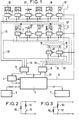
- It relates to a centralized system for acquiring individual data concerning consumption, comprising several acquisition heads, each of which provides an analog signal, which is significant for the temperature of the water in a radiator or the temperature of the hot water taken from a tap, and which each have an addressing bistable, and comprising a microprocessor, which cyclically interrogates all the acquisition heads by activating their bistable and recording, after conversion in an analog / digital signal supplied by the activated head, characterized in that digital signals from a water, gas or electricity meter are transformed in a switchable resistive dipole (figure 2, figure 3) into an impedance having one of the two impedance values according to the level of the signal to be acquired.
- a switchable resistive dipole figure 2, figure 3
- each counting head has two resistors connected between its two terminals, one. the other via a contact whose open or closed state depends on a counting signal.
- each counting head comprises two resistors connected in series between its terminals and a contact which is placed in parallel on one of the resistors and whose open or closed state depends on a counting signal.
- the measurement groups 1 and 2 bring together all the thermoelectric probes of an individual heating installation as well as all the acquisition heads for a counting signal 10 1 placed in the premises of said installation.
- Group 1 brings together four thermoelectric probes 10 placed on four radiators and two heads for acquiring a counting signal 10 t placed on a water meter and an electric meter.
- Group 2 brings together two thermoelectric probes 10 placed on two radiators and three counting heads arranged on a water meter, a gas meter and an electricity meter.
- the measuring group 3 called "common" comprises two thermoelectric probes 10 placed on the piping of the common source of thermal energy.
- the interrogation circuits 11 to which the thermoelectric probes 10 or the acquisition heads of a counting signal 10 ′ are connected are all identical. Examples were given in the main patent and its first addition. They each include a shift register stage which authorizes, depending on the state of its output, the scanning or not of the thermoelectric probe 10 or of the acquisition head of a counting signal 10 'associated by means centralized processing operating via a measurement line 21, 22 or 23 assigned to its measurement group.
- the shift register stages of the interrogation circuits 11 belonging to the same measurement group are linked together and form a shift register with serial input and parallel outputs.
- the given input of the first stage in the chain is connected to the output 24 of the microprocessor 5 and that of another stage is connected to the output of the stage which precedes it in the chain.
- timing inputs of the shift register stages of the interrogation circuits 11 belonging to the same measurement group are connected in parallel on a clock line 31, 32 or 33 leading to an output of the multiplexer 8 which, addressed by the microprocessor 5, relates one of its outputs to an output 25 of microprocessor 5 on which a clock signal is available.
- the measurement lines 21, 22, 23 coming from the measurement groups 1, 2 or 3 lead to the inputs of a demultiplexer 9 which is addressed by the microprocessor 5 and the output of which leads to the analog-digital converter 4.
- thermoelectric probe 10 and each head for acquiring a counting signal 10 behave electrically like a resistive dipole and are placed in a resistive bridge energized to allow their scanning, by the output of the stage of the shift register of the associated interrogation circuit 11.
- resistive bridge energized to allow their scanning, by the output of the stage of the shift register of the associated interrogation circuit 11.
- the shift register stages of the interrogation circuits 11 of this measuring group receive no clock signal and all have their output at state 0.
- the shift register stages of the interrogation circuits 11 of this measurement group all receive a clock signal but only l one of them has its output at state 1, this state progressing from stage to stage at the rate of the clock signal.
- the microprocessor 5 command to scan the probes and acquisition heads of a measurement group 1, 2 or 3 is carried out as follows:
- the microprocessor 5 addresses the demultiplexer 9 so as to connect the input of the analog-digital converter 4 to the measurement line 21, 22 or 23 assigned to the measurement group considered 1, 2 or 3. It generates on its output 25 a signal clock which it directs thanks to the multiplexer 8 on the clock line 31, 32 or 33 of the measurement group considered '1, 2 or 3. It finally emits on its output 24 a start signal which consists of a pulse covering a period of the clock signal and which makes it possible to change to state 1 the output of the shift register stage of the interrogation circuit placed at the head of the measurement group considered. Thereafter, the clock signal advances this state 1 along the chain of outputs of the shift registers of the interrogation circuits of the measurement group considered.
- the microprocessor 5 performs measurement cycles sequentially on all the measurement groups at a rate fast enough to capture all the counting pulses picked up by the acquisition heads.
- the microprocessor measurement cycles can repeat with a periodicity of the order of thirty seconds.
- the microprocessor 5 identifies the nature of the sensor scanned by the order of magnitude of the value of its internal resistance, the acquisition heads of a counting signal each being able to take two internal resistance values chosen from different ranges according to the type of counting performed, outside the range of resistance values of thermoelectric probes.
- thermoelectric probe From regular sampling of the resistance of a thermoelectric probe, it assesses the quantity of heat consumed by implementing a relation of the form: in which :
- Po is the power emitted by the radiator equipped with the probe considered for a difference of 30 ° between the temperature of the radiator and the ambient temperature
- N is an exponent making it possible to take account of variations in the calorific power emitted by a radiator as a function of the difference between the temperature of the radiator and the ambient temperature. It is between 0.2 and 0.4 and depends on the nature of the radiator and its installation,
- T is the average temperature of the radiator appreciated by the thermoelectric probe.
- the microprocessor 5 is also used for managing a keyboard 6 and a display 7 used for recording the characteristics of the measurement network and for controlling the display of the various consumptions.
- FIG. 2 represents the electrical diagram of a head for acquiring a counting signal. This is in the form of a dipole having two resistors connected between its terminals, one 50 directly and the other 51 via a contact 52.
- FIG. 3 a variant of the electrical diagram of a head for acquiring a counting signal.
- the latter is always in the form of a resistive dipole but its two resistors 55 and 56 are mounted in series between its terminals and the contact 57 in parallel on one of them 56.
- the contact 52 or 57 is placed on the water, gas or electricity meter equipped with the acquisition head and actuated for example by an index carried by a wheel of the meter, or by magnetic attraction of a magnetized part of this wheel.
- the two terminals of the electrical dipole are connected to an interrogation circuit in the same way as those of a thermoelectric probe.
Landscapes
- Chemical & Material Sciences (AREA)
- Engineering & Computer Science (AREA)
- Combustion & Propulsion (AREA)
- Physics & Mathematics (AREA)
- General Physics & Mathematics (AREA)
- Arrangements For Transmission Of Measured Signals (AREA)
Applications Claiming Priority (2)
| Application Number | Priority Date | Filing Date | Title |
|---|---|---|---|
| FR8306722 | 1983-04-25 | ||
| FR8306722A FR2544861B2 (fr) | 1983-04-25 | 1983-04-25 | Compteur de quantites de chaleur |
Publications (2)
| Publication Number | Publication Date |
|---|---|
| EP0124036A2 true EP0124036A2 (de) | 1984-11-07 |
| EP0124036A3 EP0124036A3 (de) | 1985-06-12 |
Family
ID=9288162
Family Applications (1)
| Application Number | Title | Priority Date | Filing Date |
|---|---|---|---|
| EP84104443A Withdrawn EP0124036A3 (de) | 1983-04-25 | 1984-04-19 | Zentrales System zum Erhalten von individuellen Verbrauchsangaben |
Country Status (4)
| Country | Link |
|---|---|
| EP (1) | EP0124036A3 (de) |
| DK (1) | DK205484A (de) |
| FI (1) | FI841552A7 (de) |
| FR (1) | FR2544861B2 (de) |
Cited By (3)
| Publication number | Priority date | Publication date | Assignee | Title |
|---|---|---|---|---|
| GB2173330A (en) * | 1985-03-29 | 1986-10-08 | Seprol Limited | Monitoring system |
| CN100408977C (zh) * | 2005-02-22 | 2008-08-06 | 艾默生网络能源系统有限公司 | 一种多模式采集电路 |
| CN101051413B (zh) * | 2007-03-30 | 2011-12-21 | 王学 | 中央空调冷热量电量监测计量系统及其监测计量方法 |
Families Citing this family (2)
| Publication number | Priority date | Publication date | Assignee | Title |
|---|---|---|---|---|
| FR2572807B1 (fr) * | 1984-11-02 | 1988-01-08 | Quille Entreprise | Procede et dispositif de mesure de consommation relative d'energie de chauffage des logements d'un immeuble collectif |
| DE3570124D1 (en) * | 1984-11-02 | 1989-06-15 | Quille Entreprise | Process and device for measuring the heating energy consumption share of individual users in a centrally heated building |
Family Cites Families (5)
| Publication number | Priority date | Publication date | Assignee | Title |
|---|---|---|---|---|
| DE2444841A1 (de) * | 1974-09-19 | 1976-09-16 | Siemens Ag | Einrichtung zur ueberwachung des flusses von energiemengen |
| JPS5264954A (en) * | 1975-11-25 | 1977-05-28 | Ricoh Co Ltd | Data collecting system |
| DE2722485A1 (de) * | 1977-05-18 | 1978-11-23 | Eberhard Dipl Ing Schlemper | System zur elektronischen ermittlung von heiz- und warmwasserkosten je verbrauchseinheit |
| NL8003920A (nl) * | 1980-07-07 | 1982-02-01 | Brooks Instr Bv | Warmtemeetstelsel. |
| DE3047510A1 (de) * | 1980-12-17 | 1982-07-22 | Helmut Ing.(grad.) 7100 Heilbronn Sigler | Verfahren zur berechnung bzw. abrechnung der heizkosten von wohnungs- oder gebaeudeeinheiten in mietshaeusern, haeusern mit eigentumswohnungen oder dergleichen sowie anlage zur durchfuehrung des verfahrens |
-
1983
- 1983-04-25 FR FR8306722A patent/FR2544861B2/fr not_active Expired
-
1984
- 1984-04-18 FI FI841552A patent/FI841552A7/fi not_active Application Discontinuation
- 1984-04-19 EP EP84104443A patent/EP0124036A3/de not_active Withdrawn
- 1984-04-24 DK DK205484A patent/DK205484A/da not_active Application Discontinuation
Cited By (3)
| Publication number | Priority date | Publication date | Assignee | Title |
|---|---|---|---|---|
| GB2173330A (en) * | 1985-03-29 | 1986-10-08 | Seprol Limited | Monitoring system |
| CN100408977C (zh) * | 2005-02-22 | 2008-08-06 | 艾默生网络能源系统有限公司 | 一种多模式采集电路 |
| CN101051413B (zh) * | 2007-03-30 | 2011-12-21 | 王学 | 中央空调冷热量电量监测计量系统及其监测计量方法 |
Also Published As
| Publication number | Publication date |
|---|---|
| EP0124036A3 (de) | 1985-06-12 |
| FI841552A0 (fi) | 1984-04-18 |
| DK205484A (da) | 1984-10-26 |
| FI841552A7 (fi) | 1984-10-26 |
| FR2544861A2 (fr) | 1984-10-26 |
| FR2544861B2 (fr) | 1987-09-25 |
| DK205484D0 (da) | 1984-04-24 |
Similar Documents
| Publication | Publication Date | Title |
|---|---|---|
| US11036189B2 (en) | Energy disaggregation techniques for low resolution whole-house energy consumption data | |
| EP1136829A1 (de) | Messverfahren für den Verbrauch eines Elementes in einem Elektrizitätsnetz | |
| EP0124036A2 (de) | Zentrales System zum Erhalten von individuellen Verbrauchsangaben | |
| EP0241424B1 (de) | Verfahren zur Bestimmung des Durchflusses eines Fluids | |
| FR2645968A1 (fr) | Procede et appareil d'analyse de signaux de courant et de tension en vue du reperage de charges a usage domestique | |
| FR2512948A1 (fr) | Perfectionnements a la mesure, l'integration et la totalisation de la consommation des fournitures distribuees par des organismes officiels de services publics ou analogues | |
| WO2009115315A1 (fr) | Dispositif de surveillance de la structure d'un vehicule | |
| FR2563676A1 (fr) | Procede de detection des changements de scene dans les films et les enregistrements video et surveillance des objets au moyen de cameras video | |
| CN120820906A (zh) | 基于高防护智能电能表的智能提示方法及系统 | |
| EP0181259A1 (de) | Verfahren und Vorrichtung zur Ermittlung des Wärmeverbrauches der einzelnen Verbraucher in einem zentral geheizten Gebäude | |
| FR2985302A1 (fr) | Dispositif d'analyse thermique | |
| CH628734A5 (en) | Meter of the quantities of heat dissipated in individual heating installations with radiators supplied by a common source | |
| CN115539850A (zh) | 一种用户端供水管网的漏水自监控方法 | |
| EP1144956B1 (de) | Vorrichtung zur gewinnung von geberstellungen | |
| FR2572807A1 (fr) | Procede et dispositif de mesure de consommation relative d'energie de chauffage des logements d'un immeuble collectif | |
| CH635934A5 (en) | Thermal metering device | |
| FR2612648A1 (fr) | Pluviometre goutte a goutte | |
| CH667328A5 (en) | Heat consumption monitoring equipment for apartment - transmits hot water supply and return temp signals to station connected by modem to telephone system | |
| Brown et al. | Non-invasive and cost effective monitoring of energy consumption patterns for electrical equipment | |
| FR2954506A1 (fr) | Dispositif, procede et systeme d'acquisition d'une mesure realisee par un compteur electrique | |
| WO1986006164A1 (fr) | Utilisation d'enregistreurs de donnees pour les determinations des valeurs k des isolations thermiques | |
| FR2514144A1 (fr) | Perfectionnement aux dispositifs d'enregistrement et de lecture de consommation d'energie electrique mesuree par des compteurs analogiques | |
| FR2495288A1 (fr) | Repartiteur de charges chauffage par systeme electronique de comptage de depenses et/ou d'economies, equipant chaque radiateur dans les immeubles a chauffage collectif, avec etablissement d'un bilan energetique en chaufferie | |
| FR2792402A1 (fr) | Procede et installation de suivi de l'evolution d'une grandeur physique au cours du temps | |
| RU61417U1 (ru) | Тестер-система для диагностики термоэлектрических батарей |
Legal Events
| Date | Code | Title | Description |
|---|---|---|---|
| PUAI | Public reference made under article 153(3) epc to a published international application that has entered the european phase |
Free format text: ORIGINAL CODE: 0009012 |
|
| AK | Designated contracting states |
Designated state(s): AT BE CH DE FR LI NL SE |
|
| PUAL | Search report despatched |
Free format text: ORIGINAL CODE: 0009013 |
|
| AK | Designated contracting states |
Designated state(s): AT BE CH DE FR LI NL SE |
|
| STAA | Information on the status of an ep patent application or granted ep patent |
Free format text: STATUS: THE APPLICATION IS DEEMED TO BE WITHDRAWN |
|
| 18D | Application deemed to be withdrawn |
Effective date: 19860213 |
|
| RIN1 | Information on inventor provided before grant (corrected) |
Inventor name: QUINTON, JACQUES |