EP0124083B1 - Bande tissée en particulier pour l'industrie papetière - Google Patents
Bande tissée en particulier pour l'industrie papetière Download PDFInfo
- Publication number
- EP0124083B1 EP0124083B1 EP84104679A EP84104679A EP0124083B1 EP 0124083 B1 EP0124083 B1 EP 0124083B1 EP 84104679 A EP84104679 A EP 84104679A EP 84104679 A EP84104679 A EP 84104679A EP 0124083 B1 EP0124083 B1 EP 0124083B1
- Authority
- EP
- European Patent Office
- Prior art keywords
- loops
- weft
- zone
- planes
- group
- Prior art date
- Legal status (The legal status is an assumption and is not a legal conclusion. Google has not performed a legal analysis and makes no representation as to the accuracy of the status listed.)
- Expired
Links
- 238000004519 manufacturing process Methods 0.000 claims abstract 2
- 238000001035 drying Methods 0.000 description 2
- 239000004744 fabric Substances 0.000 description 2
- 238000005299 abrasion Methods 0.000 description 1
- 238000009941 weaving Methods 0.000 description 1
Images
Classifications
-
- D—TEXTILES; PAPER
- D21—PAPER-MAKING; PRODUCTION OF CELLULOSE
- D21F—PAPER-MAKING MACHINES; METHODS OF PRODUCING PAPER THEREON
- D21F1/00—Wet end of machines for making continuous webs of paper
- D21F1/0027—Screen-cloths
- D21F1/0054—Seams thereof
-
- D—TEXTILES; PAPER
- D21—PAPER-MAKING; PRODUCTION OF CELLULOSE
- D21F—PAPER-MAKING MACHINES; METHODS OF PRODUCING PAPER THEREON
- D21F1/00—Wet end of machines for making continuous webs of paper
- D21F1/0027—Screen-cloths
- D21F1/0036—Multi-layer screen-cloths
Definitions
- the present invention relates to a woven strip with n weft planes intended in particular for the paper industry comprising weft threads and warp threads, some of which serve to form loops at the ends of the strip and whose areas adjacent to the loops have a thickness of m (m> 1) weft planes.
- Such woven bands are used in particular in the paper industry in particular as a drying fabric.
- the strip is wrapped around the drying cylinders of the papermaking machine and then joined.
- each zone adjacent to the loops comprises, for each weave ratio of the warp threads, a first group of warp threads forming a lower layer of p weft planes and an upper layer folded over the lower layer having (m - p) weft planes and a second group of warp threads forming a layer having m weft planes, at least some of the warp threads of the first group serving to build loops.
- the loops obtained by the warp threads of group G1 are in planes perpendicular to the wefts and are therefore much less bulky. We can therefore increase the density of these loops and consequently increase the solidity of the junction.
- the area near the loops is thicker than the rest of the strip (m> n), which makes it possible to use loops of a height greater than the thickness of the strip but obviously without exceed the thickness of the area near the loops to avoid marking of the paper by the loops and abrasion of the loops.
- the area near the loops has the same thickness as the rest of the strip, which prevents the paper from being marked by the extra thicknesses.
- the woven strip 11 shown in FIG. 1 has two ends 12 provided with loops 13. When the loops 13 are interlaced, a rod 14 can be introduced to join the strip.
- Each loop 13 is formed by a warp thread 15 which, during the reweaving with the weft threads 16, has taken the place of the neighbor warp thread 17 interrupted at a certain distance from the end 12.
- the strip has two weft planes (a, b).
- the weft threads 16 are shown by dots.
- the end of the strip was cut into four zones in order A, B, C, D, zone D comprising the loops 13 and zone A the unmodified band.
- Each armor ratio of the warp threads in zones B and C comprises a first group G1 made up of four warp threads 1, 2, 3, 4 and a second group G2 made up of four warp threads 5, 6, 7, 8.
- the warp threads 1 , 2, 3, 4 pass under a weft thread of plane a then on a weft thread of plane b located two intervals away and then under a weft thread of plane a located two intervals further and so on.
- Zone A represents the band.
- the wires 1 to 4 form four adjacent loops 13.
- the wires 1, 2.3.4 form an upper layer 20 'folded over the lower layer 20 making extra thickness on the reverse of the strip.
- Each warp thread 1, 2, 3, 4 passes successively over a weft thread and below three weft threads.
- Wires 1 to 4 are interrupted towards the end of zone C.
- the warp threads 5, 6, 7, 8 work between the two planes a, b in zone A.
- zone B the wires 6 and 8 are interrupted.
- the wires 5 and 7 work between two planes a, b in zone B and between three planes a, b, c in zone C.
- zone C wires 5 and 7 Arrived at the end of zone C wires 5 and 7 have been arranged during the reweaving by passing them in place of the wires 6 and 8, going up to the vicinity of the end of the wires 6 and 8 where they are interrupted.
- each wire 5 and 7 passes under a weft wire of plane a, then on a weft wire of plane c located two intervals further and so on until the end of zone C.
- each wire 5 and 7 passes on the weft son of plane c and under the weft son of plane a along a path symmetrical with respect to plane b of the path followed on the outward journey.
- zone C the wires 5 and 7 serve to connect the lower layer 20 to the upper layer 20 '.
- the four wires 5, 6, 7, 8 could alternatively be used up to the end of the zone C close to the zone D by making the four wires evolve between the three planes a, b and c and by cutting these four wires at the end of zone C.
- the wires from group G2, 6 and 8 are interrupted in zone B and the wires 5 and 7 constitute zone C. These wires 5 and 7 are rewoven, taking the place of wires 6 and 8 as in the example in the figure 2.
- FIGS. 2 and 3 only one end of the strip has been shown, but it is clear that the other end is preferably made in a similar manner so that the zones comprising the loops can cooperate as best as possible with the rod. tape operation.
Landscapes
- Paper (AREA)
- Woven Fabrics (AREA)
- Adhesive Tapes (AREA)
- Macromolecular Compounds Obtained By Forming Nitrogen-Containing Linkages In General (AREA)
Description
- La présente invention a trait à une bande tissée à n plans de trame destinée en particulier à l'industrie papetière comportant des fils de trame et des fils de chaîne dont certains servent à constituer aux extrémités de la bande des boucles et dont les zones voisines des boucles ont une épaisseur de m (m > 1) plans de trame.
- Pour jonctionner les boucles on peut utiliser un jonc qu'on enfile dans les boucles entrelacées ou bien utiliser des spirales qui sont enfilées dans les boucles et reliées elles-mêmes par un jonc.
- De telles bandes tissées sont utilisées notamment dans l'industrie papetière en particulier comme tissu sécheur.
- La bande est enroulée autour des cylindres de séchage de la machine à fabriquer le papier puis ensuite jonctionnée.
- Il est connu pour former la zone C voisine des boucles de retisser cette zone en faisant prendre aux fils de chaîne ayant atteint l'extrémité la place des fils de chaîne suivants qui ont été interrompus avant la zone C. Certains de ces fils de chaîne forment des boucles à l'extrémité de la bande.
- Mais ces boucles qui ne sont pas dans des plans perpendiculaires aux trames ont un encombrement dans le sens des trames supérieur à l'épaisseur d'un fil. Etant donné que ces boucles doivent être entrelacées avec les boucles de l'autre extrémité on ne peut avoir qu'une densité de 25 % de boucles à chaque extrémité.
- La bande tissée selon l'invention permettant d'obtenir une densité supérieure de boucles est caractérisée en ce que chaque zone voisine des boucles comporte pour chaque rapport d'armure des fils de chaîne un premier groupe de fils de chaîne formant une couche inférieure de p plans de trame et une couche supérieure rabattue sur la couche inférieure ayant (m - p) plans de trame et un second groupe de fils de chaîne formant une couche ayant m plans de trame, certains au moins des fils de chaîne du premier groupe servant à constituer des boucles.
- Dans la bande tissée selon l'invention les boucles obtenues par les fils de chaîne du groupe G1 sont dans des plans perpendiculaires aux trames et sont donc beaucoup moins encombrantes. On peut donc augmenter la densité de ces boucles et en conséquence accroître la solidité de la jonction.
- Selon une réalisation de l'invention la zone voisine des boucles est plus épaisse que le reste de la bande (m > n) ce qui permet d'employer des boucles d'une hauteur supérieure à l'épaisseur de la bande mais bien évidemment sans dépasser l'épaisseur de la zone voisine des boucles afin d'éviter le marquage du papier par les boucles et l'abrasion des boucles.
- Selon une réalisation de l'invention la zone voisine des boucles a la même épaisseur que le reste de la bande ce qui évite le marquage du papier par les surépaisseurs.
- L'invention va maintenant être décrite plus en détail en se référant à des modes de réalisations particuliers cités à titre d'exemple non limitatif et représentés par des dessins annexés.
- La figure 1 représente une bande tissée du type connu.
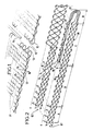
- La figure 2 représente une extrémité d'une bande tissée selon l'invention avec surépaisseur.
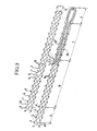
- La figure 3 représente une extrémité d'une bande tissée selon l'invention sans surépaisseur.
- La bande tissée 11 représentée sur la figure 1 comporte deux extrémités 12 munies de boucles 13. Lorsque les boucles 13 sont entrelacées on peut introduire un jonc 14 pour jonctionner la bande.
- Chaque boucle 13 est constituée par un fil de chaîne 15 qui lors du retissage avec les fils de trame 16 a pris la place du fil de chaîne de voisin 17 interrompu à une certaine distance de l'extrémité 12.
- Sur la figure 2 on a représenté l'extrémité de la bande selon l'invention.
- La bande comporte deux plans de trame (a, b). Les fils de trame 16 sont figurés par des points. On a découpé l'extrémité de la bande en quatre zones dans l'ordre A, B, C, D, la zone D comprenant les boucles 13 et la zone A la bande non modifiée.
- Chaque rapport d'armure des fils de chaîne dans les zones B et C comporte un premier groupe G1 constitué de quatre fils de chaîne 1, 2, 3, 4 et un deuxième groupe G2 constitué de quatre fils de chaîne 5, 6, 7, 8.
- L'épaisseur totale de la zone C est de trois plans de trame a, b, c (m = 3).
- L'évolution des fils du premier groupe G1 est figurée au premier plan et celle du second groupe G2 au second plan.
- Les fils de chaîne 1, 2, 3, 4 travaillent sur deux plans (p = 2) de trame a, b dans les zones A et B et également dans la zone C où ils forment la couche inférieure 20. Les fils de chaîne 1, 2, 3, 4 passent sous un fil de trame du plan a puis sur un fil de trame du plan b situé deux intervalles plus loin et puis sous un fil de trame du plan a situé deux intervalles plus loin et ainsi de suite. La zone A représente la bande. Dans la zone D les fils 1 à 4 forment quatre boucles 13 adjacentes.
- Les fils 1, 2.3.4 forment une couche supérieure 20' rabattue sur la couche inférieure 20 faisant surépaisseur sur le revers de la bande. La couche supérieure 20' est située uniquement dans la zone C et les fils 1, 2. 3, 4 travaillent dans un seul plan c (m - p = 1 ). Chaque fil de chaîne 1, 2, 3, 4 passe successivement au-dessus d'un fil de trame et au-dessous de trois fils de trame. Les fils 1 à 4 sont interrompus vers la fin de la zone C.
- Les fils de chaîne 5, 6, 7, 8 travaillent entre les deux plans a, b dans la zone A. Dans la zone B les fils 6 et 8 sont interrompus. Les fils 5 et 7 travaillent entre deux plans a, b dans la zone B et entre trois plans a, b, c dans la zone C.
- Arrivés à l'extrémité de la zone C les fils 5 et 7 ont été disposés lors du retissage en les faisant passer à la place des fils 6 et 8 en remontant jusqu'au voisinage de l'extrémité des fils 6 et 8 où ils sont interrompus. Ainsi dans la zone C chaque fil 5 et 7 passe sous un fil de trame du plan a, puis sur un fil de trame du plan c situé deux intervalles plus loin et ainsi de suite jusqu'à l'extrémité de la zone C. Puis en revenant chaque fil 5 et 7 passe sur les fils de trame du plan c et sous les fils de trame du plan a selon un chemin symétrique par rapport au plan b du chemin suivi à l'aller.
- Pour réaliser les zones B, C, D on peut utiliser une machine à épisser (machine à retisser le tissu perpendiculairement à son sens de tissage d'origine).
- Dans la zone C les fils 5 et 7 servent à relier la couche inférieure 20 à la couche supérieure 20'.
- Pour le groupe G2 on pourrait en variante utiliser les quatre fils 5, 6, 7, 8 jusqu'à l'extrémité de la zone C voisine de la zone D en faisant évoluer les quatre fils entre les trois plans a, b et c et en coupant ces quatre fils à l'extrémité de la zone C.
- Bien évidemment si dans la zone C il y avait quatre plans de trame on pourrait ajouter entre la zone B et la zone C une zone C' à trois plans de trame semblable à la zone C de la figure 2 actuelle afin que la variation de la surépaisseur ne soit pas trop brusque.
- Sur la figure 3 on a représenté une bande tissée dans laquelle il n'y a pas de surépaisseur dans la zone C voisine des boucles (m = n).
- La bande (zone A) comporte deux plans de trame a, b (n = 2).
- Dans la zone C les fils du groupe G1, 1, 2, 3, 4 forment une couche inférieure 20 à un plan (p = 1) et une couche supérieure 20' à un plan (m - p = 1) avec quatre boucles 13 dans la zone D.
- Les fils du groupe G2, 6 et 8 sont interrompus dans la zone B et les fils 5 et 7 constituent la zone C. Ces fils 5 et 7 sont retissés en prenant la place des fils 6 et 8 comme dans l'exemple de la figure 2.
- Sur les figures 2 et 3 on n'a représenté qu'une extrémité de la bande mais il est clair que l'autre extrémité est constituée de préférence d'une façon semblable pour que les zones comportant les boucles puissent coopérer au mieux au jonc- tionnement de la bande.
Claims (3)
Priority Applications (1)
| Application Number | Priority Date | Filing Date | Title |
|---|---|---|---|
| AT84104679T ATE23580T1 (de) | 1983-05-03 | 1984-04-26 | Filzgewebebahnen fuer papiermaschine. |
Applications Claiming Priority (2)
| Application Number | Priority Date | Filing Date | Title |
|---|---|---|---|
| FR8307404A FR2545514B1 (fr) | 1983-05-03 | 1983-05-03 | Bande tissee en particulier pour l'industrie papetiere |
| FR8307404 | 1983-05-03 |
Publications (2)
| Publication Number | Publication Date |
|---|---|
| EP0124083A1 EP0124083A1 (fr) | 1984-11-07 |
| EP0124083B1 true EP0124083B1 (fr) | 1986-11-12 |
Family
ID=9288565
Family Applications (1)
| Application Number | Title | Priority Date | Filing Date |
|---|---|---|---|
| EP84104679A Expired EP0124083B1 (fr) | 1983-05-03 | 1984-04-26 | Bande tissée en particulier pour l'industrie papetière |
Country Status (5)
| Country | Link |
|---|---|
| EP (1) | EP0124083B1 (fr) |
| AT (1) | ATE23580T1 (fr) |
| DE (1) | DE3461305D1 (fr) |
| FI (1) | FI78140C (fr) |
| FR (1) | FR2545514B1 (fr) |
Families Citing this family (3)
| Publication number | Priority date | Publication date | Assignee | Title |
|---|---|---|---|---|
| GB8519706D0 (en) * | 1985-08-06 | 1985-09-11 | Scapa Porritt Ltd | Papermachine &c clothing |
| EP0384550A3 (fr) * | 1986-03-31 | 1990-11-28 | Jerome B. Ackerman | Sonde de mesure |
| CN104179059B (zh) * | 2014-07-14 | 2016-04-06 | 四川环龙技术织物有限公司 | 接缝造纸毛毯的基网划线成环工艺 |
Family Cites Families (5)
| Publication number | Priority date | Publication date | Assignee | Title |
|---|---|---|---|---|
| FR1518096A (fr) * | 1966-03-11 | 1968-03-22 | J J Marx G M B H | Procédé de liaison sans fin de courroies et bandes, en particulier pour feutres etétamines de machines à papier |
| DE2064085A1 (en) * | 1970-12-28 | 1972-07-13 | Württembergische Filztuchfabrik D. Geschmay GmbH, 7320 Göppingen | Splicing of fabric ends - particularly multilayer papermaking dryer fabrics |
| US4103717A (en) * | 1976-06-18 | 1978-08-01 | William Kenyon & Sons, Inc. | Seam webbing |
| US4250822A (en) * | 1979-12-06 | 1981-02-17 | Asten Group, Inc. | Low bulk, pin-type seam for use in paper making equipment fabrics, such as dryer felts |
| US4315049A (en) * | 1979-12-06 | 1982-02-09 | Asten Group, Incorporated | Stitchless low bulk, pin-type seam for use in paper making equipment fabrics, such as dryer felts |
-
1983
- 1983-05-03 FR FR8307404A patent/FR2545514B1/fr not_active Expired
-
1984
- 1984-04-26 EP EP84104679A patent/EP0124083B1/fr not_active Expired
- 1984-04-26 AT AT84104679T patent/ATE23580T1/de active
- 1984-04-26 DE DE8484104679T patent/DE3461305D1/de not_active Expired
- 1984-04-27 FI FI841678A patent/FI78140C/fi not_active IP Right Cessation
Also Published As
| Publication number | Publication date |
|---|---|
| FI841678A0 (fi) | 1984-04-27 |
| FI841678A7 (fi) | 1984-11-04 |
| FR2545514B1 (fr) | 1985-07-05 |
| FR2545514A1 (fr) | 1984-11-09 |
| FI78140C (fi) | 1989-06-12 |
| EP0124083A1 (fr) | 1984-11-07 |
| DE3461305D1 (en) | 1987-01-02 |
| ATE23580T1 (de) | 1986-11-15 |
| FI78140B (fi) | 1989-02-28 |
Similar Documents
| Publication | Publication Date | Title |
|---|---|---|
| US4401137A (en) | Forming fabric seam and method of producing | |
| US5188884A (en) | Woven papermaking fabric having low profile seam | |
| EP0193478B1 (fr) | Armature textile utilisable pour la réalisation de complexes stratifiés | |
| EP0155712A1 (fr) | Toile destinée en particulier aux machines à papier, et son procédé de préparation | |
| CA1280309C (fr) | Dispositif de jonction pour feutre de presse humide et toile de papeterie | |
| US3238594A (en) | Method of connecting the ends of screen fabrics for producing endless forming wires for paper machines | |
| US5514456A (en) | Spiral link belt with low permeability to air and method for its production | |
| EP0030490B1 (fr) | Perfectionnements aux toiles de formage double couche pour machines à papier | |
| EP0124083A1 (fr) | Bande tissée en particulier pour l'industrie papetière | |
| CA2360842C (fr) | Jonction a armure symetrique pour bande tissee a armure asymetrique | |
| EP0251873B1 (fr) | Feutre ouvert pour partie humide | |
| US4458391A (en) | Slide-fastener half and method of making same | |
| EP0119184A1 (fr) | Procédé de tissage de tapis double face | |
| EP0106775B1 (fr) | Procédé de fabrication de toiles plastiques, en particulier pour machines à papier, et toile plastique ainsi obtenue | |
| EP0124082B1 (fr) | Bande tissée notamment pour l'industrie papetière | |
| EP0052350B1 (fr) | Procédé de renforcement de lisière de bande | |
| FR2586043A1 (fr) | Habillage pour machine a papier | |
| FR2510621A1 (fr) | Jonction cousue a axe et boucles comportant un fil monofilament plat, pour tissu, courroie ou analogue | |
| FR2466547A1 (fr) | Canal d'introduction de la trame pour metiers a tisser a buses | |
| BE1006316A3 (fr) | Toile de machine a papier. | |
| LU82790A1 (fr) | Bande de renforcement | |
| FR2715945A1 (fr) | Tissu. | |
| FR2737227A1 (fr) | Procede pour la realisation de panneaux tisses par decoupe d'un tissu dans le sens trame | |
| FR2597516A1 (fr) | Dispositif de formation de foule dans un metier a tisser | |
| FR2775470A1 (fr) | Armature textile pour bande tubulaire de convoyage |
Legal Events
| Date | Code | Title | Description |
|---|---|---|---|
| PUAI | Public reference made under article 153(3) epc to a published international application that has entered the european phase |
Free format text: ORIGINAL CODE: 0009012 |
|
| AK | Designated contracting states |
Designated state(s): AT BE CH DE FR GB IT LI NL SE |
|
| 17P | Request for examination filed |
Effective date: 19850507 |
|
| 17Q | First examination report despatched |
Effective date: 19860122 |
|
| GRAA | (expected) grant |
Free format text: ORIGINAL CODE: 0009210 |
|
| AK | Designated contracting states |
Kind code of ref document: B1 Designated state(s): AT BE CH DE FR GB IT LI NL SE |
|
| REF | Corresponds to: |
Ref document number: 23580 Country of ref document: AT Date of ref document: 19861115 Kind code of ref document: T |
|
| REF | Corresponds to: |
Ref document number: 3461305 Country of ref document: DE Date of ref document: 19870102 |
|
| ITF | It: translation for a ep patent filed | ||
| PLBI | Opposition filed |
Free format text: ORIGINAL CODE: 0009260 |
|
| 26 | Opposition filed |
Opponent name: FILZTUCHVERWALTUNGS GMBH Effective date: 19870811 |
|
| NLR1 | Nl: opposition has been filed with the epo |
Opponent name: FILZTUCHVERWALTUNGS GMBH |
|
| PLBN | Opposition rejected |
Free format text: ORIGINAL CODE: 0009273 |
|
| STAA | Information on the status of an ep patent application or granted ep patent |
Free format text: STATUS: OPPOSITION REJECTED |
|
| 27O | Opposition rejected |
Effective date: 19890126 |
|
| NLR2 | Nl: decision of opposition | ||
| PGFP | Annual fee paid to national office [announced via postgrant information from national office to epo] |
Ref country code: CH Payment date: 19930120 Year of fee payment: 10 |
|
| PGFP | Annual fee paid to national office [announced via postgrant information from national office to epo] |
Ref country code: SE Payment date: 19930122 Year of fee payment: 10 |
|
| PGFP | Annual fee paid to national office [announced via postgrant information from national office to epo] |
Ref country code: BE Payment date: 19930202 Year of fee payment: 10 |
|
| PGFP | Annual fee paid to national office [announced via postgrant information from national office to epo] |
Ref country code: DE Payment date: 19930217 Year of fee payment: 10 |
|
| PGFP | Annual fee paid to national office [announced via postgrant information from national office to epo] |
Ref country code: GB Payment date: 19930225 Year of fee payment: 10 |
|
| ITTA | It: last paid annual fee | ||
| PGFP | Annual fee paid to national office [announced via postgrant information from national office to epo] |
Ref country code: NL Payment date: 19930430 Year of fee payment: 10 Ref country code: AT Payment date: 19930430 Year of fee payment: 10 |
|
| PG25 | Lapsed in a contracting state [announced via postgrant information from national office to epo] |
Ref country code: AT Effective date: 19940426 Ref country code: GB Effective date: 19940426 |
|
| PG25 | Lapsed in a contracting state [announced via postgrant information from national office to epo] |
Ref country code: SE Effective date: 19940427 |
|
| PG25 | Lapsed in a contracting state [announced via postgrant information from national office to epo] |
Ref country code: LI Effective date: 19940430 Ref country code: BE Effective date: 19940430 Ref country code: CH Effective date: 19940430 |
|
| BERE | Be: lapsed |
Owner name: COFPA COMPAGNIE DES FEUTRES POUR PAPETERIES ET DE Effective date: 19940430 |
|
| PG25 | Lapsed in a contracting state [announced via postgrant information from national office to epo] |
Ref country code: NL Effective date: 19941101 |
|
| NLV4 | Nl: lapsed or anulled due to non-payment of the annual fee | ||
| GBPC | Gb: european patent ceased through non-payment of renewal fee |
Effective date: 19940426 |
|
| REG | Reference to a national code |
Ref country code: CH Ref legal event code: PL |
|
| PG25 | Lapsed in a contracting state [announced via postgrant information from national office to epo] |
Ref country code: DE Effective date: 19950103 |
|
| EUG | Se: european patent has lapsed |
Ref document number: 84104679.0 Effective date: 19941110 |
|
| PGFP | Annual fee paid to national office [announced via postgrant information from national office to epo] |
Ref country code: FR Payment date: 19951228 Year of fee payment: 13 |
|
| PG25 | Lapsed in a contracting state [announced via postgrant information from national office to epo] |
Ref country code: FR Free format text: LAPSE BECAUSE OF NON-PAYMENT OF DUE FEES Effective date: 19971231 |
|
| REG | Reference to a national code |
Ref country code: FR Ref legal event code: ST |