EP0124108A2 - Korrekturschaltung zur Stabilisierung eines statischen Magnetfeldes in einer magnetischen Kernresonanzapparatur und magnetische Kernresonanzapparatur mit einer solchen Schaltung - Google Patents
Korrekturschaltung zur Stabilisierung eines statischen Magnetfeldes in einer magnetischen Kernresonanzapparatur und magnetische Kernresonanzapparatur mit einer solchen Schaltung Download PDFInfo
- Publication number
- EP0124108A2 EP0124108A2 EP84104770A EP84104770A EP0124108A2 EP 0124108 A2 EP0124108 A2 EP 0124108A2 EP 84104770 A EP84104770 A EP 84104770A EP 84104770 A EP84104770 A EP 84104770A EP 0124108 A2 EP0124108 A2 EP 0124108A2
- Authority
- EP
- European Patent Office
- Prior art keywords
- magnetic field
- echo signal
- static magnetic
- slice
- deviation
- Prior art date
- Legal status (The legal status is an assumption and is not a legal conclusion. Google has not performed a legal analysis and makes no representation as to the accuracy of the status listed.)
- Granted
Links
Images


Classifications
-
- G—PHYSICS
- G01—MEASURING; TESTING
- G01R—MEASURING ELECTRIC VARIABLES; MEASURING MAGNETIC VARIABLES
- G01R33/00—Arrangements or instruments for measuring magnetic variables
- G01R33/20—Arrangements or instruments for measuring magnetic variables involving magnetic resonance
- G01R33/24—Arrangements or instruments for measuring magnetic variables involving magnetic resonance for measuring direction or magnitude of magnetic fields or magnetic flux
-
- G—PHYSICS
- G01—MEASURING; TESTING
- G01R—MEASURING ELECTRIC VARIABLES; MEASURING MAGNETIC VARIABLES
- G01R33/00—Arrangements or instruments for measuring magnetic variables
- G01R33/20—Arrangements or instruments for measuring magnetic variables involving magnetic resonance
- G01R33/28—Details of apparatus provided for in groups G01R33/44 - G01R33/64
- G01R33/38—Systems for generation, homogenisation or stabilisation of the main or gradient magnetic field
- G01R33/389—Field stabilisation, e.g. by field measurements and control means or indirectly by current stabilisation
-
- G—PHYSICS
- G01—MEASURING; TESTING
- G01R—MEASURING ELECTRIC VARIABLES; MEASURING MAGNETIC VARIABLES
- G01R33/00—Arrangements or instruments for measuring magnetic variables
- G01R33/20—Arrangements or instruments for measuring magnetic variables involving magnetic resonance
- G01R33/44—Arrangements or instruments for measuring magnetic variables involving magnetic resonance using nuclear magnetic resonance [NMR]
- G01R33/48—NMR imaging systems
- G01R33/54—Signal processing systems, e.g. using pulse sequences ; Generation or control of pulse sequences; Operator console
- G01R33/56—Image enhancement or correction, e.g. subtraction or averaging techniques, e.g. improvement of signal-to-noise ratio and resolution
- G01R33/565—Correction of image distortions, e.g. due to magnetic field inhomogeneities
- G01R33/56563—Correction of image distortions, e.g. due to magnetic field inhomogeneities caused by a distortion of the main magnetic field B0, e.g. temporal variation of the magnitude or spatial inhomogeneity of B0
Definitions
- the present invention relates to a correction circuit for a static magnetic field of a nuclear magnetic resonance (NMR) apparatus wherein a spin density and a relaxation-time of specific nucleus are measured by utilizing the NMR phenomenon occurred in the object, e.g., a patient, and also an NMR apparatus into which the above-identified correction circuit is employed.
- NMR nuclear magnetic resonance
- the first-mentioned NMR diagnostic apparatus is known from, for example, U.S. Patent 4,254,778 issued on March 10, 1981 to Clow.
- a tomographic image, or a proton density image of a patient may be obtained in the NMR diagnostic apparatus.
- the tomographic image is, for example, defined as the same obtained by calculating data on, e.g., the spin density of the specific nucleus with respect to the given slice of the patient.
- the tomographic image of the known NMR diagnostic apparatus may be obtained as follows.
- a uniform static magnetic field H 0 is applied to a patient P along the Z-axis (direction parallel to the longitudinal axis of the patient P).
- a linear gradient magnetic field G z is generated by a pair of gradient field coils 1A and 1B and is superposed on the static magnetic field H 0 along the Z-axis.
- a specific nucleus in the static magnetic field H 0 resonates at an angular frequency ⁇ 0 given as follows: where y is the proton gyromagnetic ratio which is inherent to the specific type of nucleus.
- a rotating magnetic field H 1 for resonating only the specific nucleus at the angular frequency ⁇ 0 is applied to the patient P through a pair of transmitter coils 2A and 28.
- an NMR phenomenon selectively occurs only at a slice (positioned on the X-Y plane perpendicular to the Z-axis) which is selected by the gradient field G z along the Z-axis and which is represented by reference symbol "S".
- This NMR phenomenon is detected as an NMR signal, e.g., an FID signal or echo signal through a pair of receiver coils 3A and 3B.
- the resultant NMR signal is Fourier-transformed to obtain a single spectrum of a specific nucleus spin with respect to the rotating angular frequency.
- projection images within the X-Y plane corresponding to the slice must be obtained from a multiple of directions.
- the slice is excited to generate the NMR phenomenon, and another linear gradient magnetic field G XY is superposed by coils (not shown) on the static field H 0 along the specific gradient direction in the X-Y plane.
- Equivalent field force lines at the slice of the patient P become parallel lines perpendicular to the gradient direction of the linear gradient field G XY .
- the rotating angular frequency of the nucleus spin of the specific nucleus on each equivalent field force line is represented by equation (1) above.
- the NMR signal e.g., an FID signal or echo signal detected under this condition is Fourier-transformed to obtain projection information (i.e., one-dimensional information of projection parallel to the equivalent field force lines) of the slice along the linear gradient field G XY .
- the projection information toward the multiple directions within the X-Y plane can be obtained in the same manner as described above.
- Image reconstruction processing is then performed in accordance with the projection information, thereby obtaining a tomographic iamge.
- a diagnostic NMR apparatus of this type drifts inevitably occur in a generation section (i.e., power supply) of the uniform static magnetic field H O and other components of the apparatus. Therefore, it is difficult to maintain predetermined resonant conditions for a long period of time.
- the conditions of the excited slice tends to be gradually deviated from the predetermined resonant conditions over time.
- a deviation ⁇ in the resonant frequency w 0 occurs on the order of several kilohertzs, resonance no longer occurs, and thus the NMR excitation cannot be realized.
- the deviation falls within the range of several ten hertzs to several hundred hertzs, the excitation occurs to some extent. However, the image becomes unclear and the artifact appears. Therefore, in the diagnostic NMR apparatus, the deviation ⁇ must be less than several hertzs.
- Method (I) i.e., the adjustment of the field strength of the static magnetic field H O is considered desirable since it is free from the above-described problems (1) and (2).
- the resonant conditions will be stably maintained in accordance with method (I) in this specification.
- a conventional method for variably adjusting the field strength of the static magnetic field H 0 to correct deviations in resonant conditions is employed in an NMR apparatus for material measurement.
- a relatively compact probe head coil is separately provided to detect a static field deviation ⁇ H 0 .
- a method using a phantom which is independent of the main measuring phantom is also proposed wherein a magneto sensor, e.g., a magnetoresistive device is used in place of the deviation detecting probe.head coil.
- a magneto sensor e.g., a magnetoresistive device is used in place of the deviation detecting probe.head coil.
- Another object of the present invention is to provide an NMR diagnostic apparatus into which the above-described correction circuit is employed.
- a correction circuit for a static magnetic field of a nuclear magnetic resonance apparatus in that the static magnetic field is uniformly applied to a slice of an object under investigation, a gradient magnetic field is applied to the object in a direction prependicular to the slice of the object, and first and second exciting pulses are selectively applied to excite the slice of the object in conjunction with the static and gradient magnetic fields, whereby an echo signal is produced in the excited slice of the object, comprising:
- no specific constructive element e.g., the probe head coil is additionally required.
- a precise correction on the deviation of the static magnetic field can be realized so that high spatial resolution can be obtained in the NMR imaging.
- the calculated static field deviation ⁇ H 0 is fed back to a static field power supply, thereby adjusting the field strength of the static magnetic field H o and correcting the resonant conditions.
- This control technique is so-called “magnetic field locked loop” (referred to as “MFLL” control hereinafter).
- the basic circuit configuration i.e., a correction circuit 100
- a correction circuit 100 will be described with reference to Fig. 2 to perform "MFLL" control associated with the present invention.
- the general NMR apparatus is operated in the following manner to obtain a predetermined echo signal.
- a static field H 0 is applied to the patient in the normal manner.
- Only a gradient field perpendicular to the slice of the patient is applied to the patient for a predetermined time in a direction perpendicular to the slice.
- the gradient field along the direction (X-Y direction) perpendicular to the slice becomes G Z .
- only the gradient field G Z is applied to the patient at predetermined moments for a predetermined time such that the gradient field G Z is superposed on the field H0.
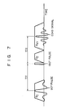
- 90° and 180° exciting pulses are selectively applied to the slice.
- these exciting pulses are applied to the slice in conjunction with the fields H O and G Z in accordance with a 90° pulse - T - 180° pulse ( T : given time interval) sequence.
- T 90° pulse - T - 180° pulse
- the echo signal can be obtained from the slice.
- Figs. 5 and 7. It should be noted that the second gradient magnetic field G XY is not used to correct the static magnetic field H 0 in the "MFLL" control.
- This echo signal is detected by a signal detector 51 to obtain phase components of the echo signal. These phase components are converted by an A/D converter 52 to obtain a digital echo signal. The digital echo signal is then Fourier-transformed by a Fourier transform device 53, thereby obtaining projection data signal (see Fig. 3) of the detected echo signal. A.maximum peak value of the projection data signal is detected by a max. peak detector 54. This peak value is supplied to a ⁇ detector 55 which then detects a frequency shift ⁇ with respect to the nuclear magnetic resonant frequency w 0 . As is apparent from Fig.
- this projection data signal has a small DC-component peak near the 0 point of the coordinate system and a magnitude along the axis plotting the frequency w is small because the gradient field along the slice- direction is not applied.
- the D/A converter 57 may be omitted from the correction circuit shown in Fig. 2 if the H 0 power supply is controllable in a digital control signal.
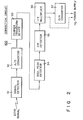
- Fig. 4 shows an NMR diagnostic apparatus 200 using the correction circuit 100 according to an embodiment of the present invention.
- the configuration of the apparatus 200 shown in Fig. 4 is as follows.
- Reference numerals 4a and 4b denote air coil assemblies for applying the uniform static magnetic field H 0 to the patient P; 5, a first gradient field coil assembly for generating first gradient magnetic fields G z and/or G Z along the direction (Z-axis since the slice is defined as the X-Y plane) perpendicular to the slice S; 6, a second gradient field coil assembly for generating second gradient magnetic fields GXV and/or -G XY along the slice (the respective directions in the X-Y plane); 7, an RF coil assembly for transmitter/receiver; 8, a phase detector of a quadrature phase detection method for detecting the in-phase component (real part) and 90° phase component (imaginary part) of the echo signal with respect to the reference signal; 9, a transmitter for generating 90° and 180° exciting pulses consisting of RF pulses of an
- Reference numeral 13 denotes a power supply for static magnetic field in order to excite the air coil assemblies 4A and 4B so as to generate the static magnetic field H 0 ; and 14, a static field control circuit for controlling the power supply 13 in accordance with the data generated from the high-speed Fourier transform device 12 when the MFLL control is performed.
- Reference numeral 15 denotes an image reconstruction devide for performing image reconstruction processing in accordance with an output of the high-speed Fourier transform device 12 when the MFLL control is not performed; 16, a display device for displaying an image obtained by the image reconstruction device; and 17, a timing control system for controlling operation timings of the components described above.
- the correction circuit 100 comprises a part surrounded by a dotted line, and that the field H 0 is continuously applied to the slice until the echo signal acquisition is performed.
- the air coil assemblies 4A and 4B are energized by the H 0 power supply 13 to apply the uniform static magnetic field H O to the patient P.
- the first gradient magnetic field +G Z having the gradient with respect to the direction (Z direction) perpendicular to the slice (located within the X-Y plane) is superposed by the first gradient field coil assembly 5 on the uniform static magnetic field H 0 .
- the 90° exciting pulse is applied from the transmitter 9 to the patient P in the field through the RF coil assembly 7.
- the second gradient magnetic field +G XY is superposed by the gradient field coil assembly 6 on the static magnetic field H 0 along the direction (X-Y plane) parallel to the slice S.
- the 180° exciting pulse is applied from the transmitter 9 to the patient P through the RF coil assembly 7.
- the 180° exciting pulse is applied to the patient when a time period T 1 has elapsed after the application of the 90° exciting pulse.
- the first gradient magnetic field +G Z is superposed by the gradient field coil assembly 5 to the static magnetic field H 0 for a predetermined time period.
- the echo signal is received from the patient P through the RF coil assembly 7 when the time period T 1 has elapsed after the application of the 180° exciting pulse.
- the echo signal received by the RF coil assembly 7 is phase-detected by the phase detector 8.
- the detected signal is converted by the A/D converter 10 to a digital signal.
- the digital signal is supplied to the adder 11.
- the above operation is repeated to obtain a sum of the echo signal data, and a mean value is obtained from the sum. It should be noted that the mean value of the sum is obtained to improve the S/N ratio.
- the mean echo signal data is Fourier-transformed by the high-speed Fourier transform device 12, thereby obtaining the projection data signal shown in Fig. 3.
- Other projection data signals are then obtained by changing the gradient directions of the second gradient magnetic field G XY , and image reconstruction is performed by the image reconstruction device 15.
- the resultant tomographic image is then displayed on a display device 16.
- a pulse sequence is adopted which excludes the application of the second gradient magnetic field G XY by means of the second gradient field coil assembly 6 from the pulse sequence employed in normal NMR imaging, thereby obtaining the echo signal.
- the uniform static magnetic field H 0 is applied to the patient P by means of the air coil assemblies 4A and 4B.
- the first gradient magnetic field G z is superposed by the first gradient coil assembly 5 on the uniform static magnetic field H 0 along the direction perpendicular to the desired slice for a predetermined time period.
- the 90° exciting pulse is applied by the RF coil assembly 7 to the patient P within the fields H O and G Z .
- the 180° exciting pulse is applied by the RF coil assembly 7 to the patient P without applying the second gradient magnetic field G XY thereto.
- the first gradient magnetic field G z is superposed by the first gradient field coil assembly 5 again on the static magnetic field H 0 for a predetermined time period.
- the echo signal is received by the RF coil assembly 7 from the patient P when a predetermined time interval has elapsed.
- the receiving echo signal is phase-detected by the phase detector 8, and the detected signal is then converted by the A/D converter 10 to a digital signal.
- the digital signal is then supplied to the adder 11.
- the above operation is repeated, and the mean data signal is then obtained from the sum.
- the mean echo data signal is Fourier-transformed by the high-speed Fourier transform device 12, thereby obtaining the projection data signal shown in Fig. 3.
- This projection data signal is supplied to the control circuit 14 (see Fig. 6) for static field which is not used in normal NMR imaging.
- the control circuit 14 detects the maximum peak value of the projection data signal.
- a deviation ⁇ in angular frequency (see Fig. 3) is calculated in accordance with the detected peak value.
- the static field deviation ⁇ H 0 is calculated in accordance with equation (2), thereaby controlling the H 0 power supply 13.
- a max. peak detector 54 for detecting the maximum peak value of the projection data signal generated by the FFT 12.
- the ⁇ detector (Aw DTC) 55 for detecting the frequency deviation ⁇ from the nuclear magnetic resonant frequency w plotted along the abscissa.
- a multiplier (1/y MLT) 56 is provided to multiply the deviation ⁇ obtained from the ⁇ detector 55 by 1/y in accordance with equation (2) so as to calculate a static field deviation ⁇ H.
- a D/A (digital-to-analogue) converter 57 is provided to convert to an analogue signal the static field deviation AH as the correction value calculated by the multiplier 56.
- the analogue signal from the D/A converter 57 is supplied to an operational amplifier 60 of the H 0 power supply 13, so that the static magnetic field H 0 is corrected to eliminate the frequency deviation ⁇ .
- a static field current I derived from an output voltage Ve from the D/A converter 57 and a shunt resistor R is supplied to the first gradient coil assemblies 4A and 4B so as to perform correction.
- the MFLL control is performed to optimally correct the static magnetic field H 0 within a short period of time.
- special external devices e.g., probe head coil need not be added for correction.
- Fig. 8 is a flow chart for showing the sequence of the MFLL control described above. The MFLL control operation will be described with reference to the flow chart.
- the echo signal is obtained under the prescribed conditions and is processed by the circuits shown in Figs. 4 to 6, thereby obtaining the projection data signal.
- the static field shift ⁇ is calculated.
- the desired static magnetic field correction value ⁇ H 0 is derived from the static field shift ⁇ .
- the resultant value ⁇ H 0 is added to a previous correction value H On , so that an updated correction value H 0n+1 is obtained.
- This correction value H 0n+1 is supplied to the H 0 power supply 13.
- the exciting current I for static magnetic field generation is changed as described in association with Fig. 6, thereby changing the field strength of the static field H 0 .
- the echo signal is received again to perform signal processing in the same manner as described above, and the shift ⁇ is obtained again. If the shift Aw is not zero, MFLL control is started to change the field strength of the static field H 0 .
- the pulse sequence of 90° pulse - 180° pulse is used.
- a pulse sequence of 180° pulse - 90° pulse - 180° pulse can be used in place of the 90° pulse - 180° pulse sequence to obtain the prescribed echo signals. It is essential that the 180° pulse is finally applied to the patient to obtain the echo signal.
- the positive and negative components ( + G z and -G Z ) of the first field gradient field G z may be sequentially applied to the slice of the patient P.
- the adder 11, the high-speed Fourier transform device 12, the static field control circuit 14 and the timing control system 17 shown in Fig. 4 may be replaced with a microcomputer, and the functions of the components shown in Fig. 4 can be performed by software.
- the microcomputer constituting the image reconstruction device 15 can be commonly used as the microcomputer described above. In this manner, the new configuration is the same as that in normal NMR imaging from the software point of view.
- the longitudinal axis of the object is defined to be parallel to the Z-axis of the X-Y-Z coordinate system.
- the magnetic field G Z is used as the first gradient magnetic field to obtain the echo signal for the MFLL control.
- the present invention is not limited to this arrangement.
- the first gradient field when the longitudinal axis is defined to be parallel to another axis of the X-Y-Z coordinate system, the first gradient field apparently corresponds to G X or G Y .
Landscapes
- Physics & Mathematics (AREA)
- Condensed Matter Physics & Semiconductors (AREA)
- General Physics & Mathematics (AREA)
- Health & Medical Sciences (AREA)
- General Health & Medical Sciences (AREA)
- Nuclear Medicine, Radiotherapy & Molecular Imaging (AREA)
- Radiology & Medical Imaging (AREA)
- Engineering & Computer Science (AREA)
- Signal Processing (AREA)
- High Energy & Nuclear Physics (AREA)
- Magnetic Resonance Imaging Apparatus (AREA)
Applications Claiming Priority (2)
| Application Number | Priority Date | Filing Date | Title |
|---|---|---|---|
| JP76424/83 | 1983-04-30 | ||
| JP58076424A JPS59200947A (ja) | 1983-04-30 | 1983-04-30 | Mri装置における静磁場強度調整方法 |
Publications (3)
| Publication Number | Publication Date |
|---|---|
| EP0124108A2 true EP0124108A2 (de) | 1984-11-07 |
| EP0124108A3 EP0124108A3 (en) | 1986-03-19 |
| EP0124108B1 EP0124108B1 (de) | 1989-06-21 |
Family
ID=13604792
Family Applications (1)
| Application Number | Title | Priority Date | Filing Date |
|---|---|---|---|
| EP84104770A Expired EP0124108B1 (de) | 1983-04-30 | 1984-04-27 | Korrekturschaltung zur Stabilisierung eines statischen Magnetfeldes in einer magnetischen Kernresonanzapparatur und magnetische Kernresonanzapparatur mit einer solchen Schaltung |
Country Status (4)
| Country | Link |
|---|---|
| US (1) | US4644473A (de) |
| EP (1) | EP0124108B1 (de) |
| JP (1) | JPS59200947A (de) |
| DE (1) | DE3478762D1 (de) |
Cited By (2)
| Publication number | Priority date | Publication date | Assignee | Title |
|---|---|---|---|---|
| DE3545897A1 (de) * | 1984-12-26 | 1986-07-03 | Kabushiki Kaisha Toshiba, Kawasaki, Kanagawa | Vorrichtung zur magnetischen kernresonanzabbildung |
| EP0337588A3 (en) * | 1988-04-14 | 1990-12-12 | The Regents Of The University Of California | Mri compensated for spurious nmr frequency/phase shifts caused by spurious changes in magnetic fields during nmr data measurement processes |
Families Citing this family (9)
| Publication number | Priority date | Publication date | Assignee | Title |
|---|---|---|---|---|
| JPS61254839A (ja) * | 1985-05-08 | 1986-11-12 | Toshiba Corp | 磁気共鳴イメ−ジング装置 |
| US4731865A (en) * | 1986-03-27 | 1988-03-15 | General Electric Company | Digital image correction |
| JP2642362B2 (ja) * | 1987-09-30 | 1997-08-20 | 株式会社東芝 | 磁気共鳴映像装置 |
| JPH01155836A (ja) * | 1987-12-14 | 1989-06-19 | Toshiba Corp | 磁気共鳴イメージング装置 |
| JP2741885B2 (ja) * | 1989-02-17 | 1998-04-22 | 株式会社日立製作所 | 磁気共鳴を用いた検査装置におけるデータ処理方法 |
| DE19508238A1 (de) * | 1995-03-08 | 1996-09-12 | Siemens Ag | Verfahren zur Magnetfeldstabilisierung bei einem Magneten für Kernspintomographieanlagen und Anordnung zur Durchführung des Verfahrens |
| US5914599A (en) * | 1995-08-18 | 1999-06-22 | National Research Council Of Canada | Compensation for inhomogeneity of the field generated by the RF coil in a nuclear magnetic resonance system |
| US6037775A (en) * | 1996-08-13 | 2000-03-14 | Fonar Corporation | Method and apparatus for magnetic field stabilization in a MRI system |
| JP3866537B2 (ja) * | 2001-06-28 | 2007-01-10 | ジーイー・メディカル・システムズ・グローバル・テクノロジー・カンパニー・エルエルシー | 磁気共鳴撮影装置 |
Family Cites Families (10)
| Publication number | Priority date | Publication date | Assignee | Title |
|---|---|---|---|---|
| DE1798079C3 (de) * | 1967-08-21 | 1975-03-06 | Varian Associates, Palo Alto, Calif. (V.St.A.) | Verfahren zur Messung der gyromagnetischen Resonanz und zur Durchführung des Verfahrens geeignetes Spinresonanzspektrometer |
| DE2352315C2 (de) * | 1973-10-18 | 1975-12-11 | Bruker-Physik Ag, 7501 Forchheim | Verfahren zur Stabilisierung des Verhältnisses von MeBfrequenz zu Magnetfeldstärke bei einem Spinresonanzspektrometer |
| GB1596160A (en) * | 1976-12-15 | 1981-08-19 | Nat Res Dev | Nuclear magnetic resonance apparatus and methods |
| US4093910A (en) * | 1977-02-22 | 1978-06-06 | Varian Associates, Inc. | Nuclear magnetic resonance pick-up circuit for control of resonance conditions |
| GB1602913A (en) * | 1978-02-15 | 1981-11-18 | Nat Res Dev | Pulsed nuclear magnetic resonance spectrometers |
| GB2027208B (en) * | 1978-08-05 | 1982-12-15 | Emi Ltd | Magnetic field correction in nmr apparatus |
| US4284950A (en) * | 1978-08-05 | 1981-08-18 | E M I Limited | Imaging systems |
| GB2053481B (en) * | 1979-07-06 | 1983-04-07 | Newport Instr Ltd | Nmr spectrometers |
| JPS57192541A (en) * | 1981-05-25 | 1982-11-26 | Tokyo Shibaura Electric Co | Nuclear magnetic rosonance apparatus for diagnosis |
| JPS5848839A (ja) * | 1981-09-18 | 1983-03-22 | Hitachi Ltd | 核磁気共鳴を用いた検査装置 |
-
1983
- 1983-04-30 JP JP58076424A patent/JPS59200947A/ja active Pending
-
1984
- 1984-04-25 US US06/603,726 patent/US4644473A/en not_active Expired - Fee Related
- 1984-04-27 EP EP84104770A patent/EP0124108B1/de not_active Expired
- 1984-04-27 DE DE8484104770T patent/DE3478762D1/de not_active Expired
Cited By (2)
| Publication number | Priority date | Publication date | Assignee | Title |
|---|---|---|---|---|
| DE3545897A1 (de) * | 1984-12-26 | 1986-07-03 | Kabushiki Kaisha Toshiba, Kawasaki, Kanagawa | Vorrichtung zur magnetischen kernresonanzabbildung |
| EP0337588A3 (en) * | 1988-04-14 | 1990-12-12 | The Regents Of The University Of California | Mri compensated for spurious nmr frequency/phase shifts caused by spurious changes in magnetic fields during nmr data measurement processes |
Also Published As
| Publication number | Publication date |
|---|---|
| US4644473A (en) | 1987-02-17 |
| JPS59200947A (ja) | 1984-11-14 |
| EP0124108A3 (en) | 1986-03-19 |
| DE3478762D1 (en) | 1989-07-27 |
| EP0124108B1 (de) | 1989-06-21 |
Similar Documents
| Publication | Publication Date | Title |
|---|---|---|
| US5450010A (en) | Magnetic resonance imaging method and apparatus employing eddy current compensation by modification of gradient size | |
| JP3529446B2 (ja) | Epi及びgrase mriにおける読み出し傾斜磁界極性の補正方法 | |
| JP4201993B2 (ja) | Nmrイメージング操作中に誘導される渦電流の測定および補償のための装置及びシステム | |
| EP0332383B1 (de) | Kompensation eines Polarisations- und Gradientenfeldes | |
| US6507190B1 (en) | Method and apparatus for compensating polarizing fields in magnetic resonance imaging | |
| US5055791A (en) | Nmr machine phantom and a method of measuring the characteristics of a magnetic field using such a phantom | |
| US20050033156A1 (en) | Method and magnetic resonance tomography apparatus for correcting changes in the basic magnetic field | |
| JPH0856928A (ja) | 表面コイル配設により核磁化分布を決定するmr法 | |
| JP2716889B2 (ja) | 磁石の高速補正法 | |
| US4866386A (en) | High signal-to-noise, rapid calibration of RF pulses | |
| EP0124108B1 (de) | Korrekturschaltung zur Stabilisierung eines statischen Magnetfeldes in einer magnetischen Kernresonanzapparatur und magnetische Kernresonanzapparatur mit einer solchen Schaltung | |
| EP1004892A1 (de) | Kompensierung eines MRI-Systems für verbleibende Magnetisierung | |
| JPH08206094A (ja) | 核スピン断層撮影装置 | |
| GB2173001A (en) | Diagnostic apparatus employing nuclear magnetic resonance | |
| US6470203B2 (en) | MR imaging method, phase error measuring method and MRI system | |
| US6545476B1 (en) | Method for shimming a magnet system of a MR tomography apparatus and MR tomography apparatus for the implementation of the method | |
| WO1988006288A1 (en) | Method and apparatus for nmr imaging | |
| EP0439119A2 (de) | Anordnung zur Bilderzeugung mittels magnetischer Resonanz | |
| EP0431684A1 (de) | Apparat zur Bilderzeugung mittels magnetischer Resonanz mit Optimaleinstellung des Detektorkreises und mit erweitertem dynamischem Bereich | |
| JP3018076B2 (ja) | 核磁気共鳴を用いた検査装置 | |
| JP2528864B2 (ja) | 核磁気共鳴を用いた検査装置 | |
| JP3887082B2 (ja) | 磁気共鳴イメージング装置 | |
| JPH049414B2 (de) | ||
| US4661776A (en) | Nuclear magnetic resonance diagnostic apparatus | |
| EP0280930A2 (de) | Apparat und Verfahren zur Bilderzeugung mittels magnetischer Resonanz |
Legal Events
| Date | Code | Title | Description |
|---|---|---|---|
| PUAI | Public reference made under article 153(3) epc to a published international application that has entered the european phase |
Free format text: ORIGINAL CODE: 0009012 |
|
| 17P | Request for examination filed |
Effective date: 19840523 |
|
| AK | Designated contracting states |
Designated state(s): DE FR GB |
|
| PUAL | Search report despatched |
Free format text: ORIGINAL CODE: 0009013 |
|
| AK | Designated contracting states |
Kind code of ref document: A3 Designated state(s): DE FR GB |
|
| 17Q | First examination report despatched |
Effective date: 19871110 |
|
| GRAA | (expected) grant |
Free format text: ORIGINAL CODE: 0009210 |
|
| AK | Designated contracting states |
Kind code of ref document: B1 Designated state(s): DE FR GB |
|
| REF | Corresponds to: |
Ref document number: 3478762 Country of ref document: DE Date of ref document: 19890727 |
|
| ET | Fr: translation filed | ||
| PLBE | No opposition filed within time limit |
Free format text: ORIGINAL CODE: 0009261 |
|
| STAA | Information on the status of an ep patent application or granted ep patent |
Free format text: STATUS: NO OPPOSITION FILED WITHIN TIME LIMIT |
|
| 26N | No opposition filed | ||
| PGFP | Annual fee paid to national office [announced via postgrant information from national office to epo] |
Ref country code: FR Payment date: 19970409 Year of fee payment: 14 |
|
| PGFP | Annual fee paid to national office [announced via postgrant information from national office to epo] |
Ref country code: GB Payment date: 19970418 Year of fee payment: 14 |
|
| PGFP | Annual fee paid to national office [announced via postgrant information from national office to epo] |
Ref country code: DE Payment date: 19970505 Year of fee payment: 14 |
|
| PG25 | Lapsed in a contracting state [announced via postgrant information from national office to epo] |
Ref country code: GB Free format text: LAPSE BECAUSE OF NON-PAYMENT OF DUE FEES Effective date: 19980427 |
|
| PG25 | Lapsed in a contracting state [announced via postgrant information from national office to epo] |
Ref country code: FR Free format text: THE PATENT HAS BEEN ANNULLED BY A DECISION OF A NATIONAL AUTHORITY Effective date: 19980430 |
|
| GBPC | Gb: european patent ceased through non-payment of renewal fee |
Effective date: 19980427 |
|
| PG25 | Lapsed in a contracting state [announced via postgrant information from national office to epo] |
Ref country code: DE Free format text: LAPSE BECAUSE OF NON-PAYMENT OF DUE FEES Effective date: 19990202 |
|
| REG | Reference to a national code |
Ref country code: FR Ref legal event code: ST |