EP0124109B1 - Elektro-magnetisches Relais mit symmetrischer Rückwirkung - Google Patents
Elektro-magnetisches Relais mit symmetrischer Rückwirkung Download PDFInfo
- Publication number
- EP0124109B1 EP0124109B1 EP84104772A EP84104772A EP0124109B1 EP 0124109 B1 EP0124109 B1 EP 0124109B1 EP 84104772 A EP84104772 A EP 84104772A EP 84104772 A EP84104772 A EP 84104772A EP 0124109 B1 EP0124109 B1 EP 0124109B1
- Authority
- EP
- European Patent Office
- Prior art keywords
- core
- pole
- armature
- plates
- pieces
- Prior art date
- Legal status (The legal status is an assumption and is not a legal conclusion. Google has not performed a legal analysis and makes no representation as to the accuracy of the status listed.)
- Expired
Links
- 239000000696 magnetic material Substances 0.000 claims abstract 11
- 230000005415 magnetization Effects 0.000 abstract description 2
- XEEYBQQBJWHFJM-UHFFFAOYSA-N Iron Chemical group [Fe] XEEYBQQBJWHFJM-UHFFFAOYSA-N 0.000 description 39
- 229910052742 iron Inorganic materials 0.000 description 10
- 230000005484 gravity Effects 0.000 description 6
- 238000010276 construction Methods 0.000 description 3
- 230000000712 assembly Effects 0.000 description 1
- 238000000429 assembly Methods 0.000 description 1
- 230000004907 flux Effects 0.000 description 1
- 230000000630 rising effect Effects 0.000 description 1
Images
Classifications
-
- H—ELECTRICITY
- H01—ELECTRIC ELEMENTS
- H01H—ELECTRIC SWITCHES; RELAYS; SELECTORS; EMERGENCY PROTECTIVE DEVICES
- H01H50/00—Details of electromagnetic relays
- H01H50/16—Magnetic circuit arrangements
- H01H50/18—Movable parts of magnetic circuits, e.g. armature
-
- H—ELECTRICITY
- H01—ELECTRIC ELEMENTS
- H01H—ELECTRIC SWITCHES; RELAYS; SELECTORS; EMERGENCY PROTECTIVE DEVICES
- H01H51/00—Electromagnetic relays
- H01H51/22—Polarised relays
- H01H51/2227—Polarised relays in which the movable part comprises at least one permanent magnet, sandwiched between pole-plates, each forming an active air-gap with parts of the stationary magnetic circuit
-
- H—ELECTRICITY
- H01—ELECTRIC ELEMENTS
- H01H—ELECTRIC SWITCHES; RELAYS; SELECTORS; EMERGENCY PROTECTIVE DEVICES
- H01H50/00—Details of electromagnetic relays
- H01H50/10—Electromagnetic or electrostatic shielding
-
- H—ELECTRICITY
- H01—ELECTRIC ELEMENTS
- H01H—ELECTRIC SWITCHES; RELAYS; SELECTORS; EMERGENCY PROTECTIVE DEVICES
- H01H50/00—Details of electromagnetic relays
- H01H50/14—Terminal arrangements
-
- H—ELECTRICITY
- H05—ELECTRIC TECHNIQUES NOT OTHERWISE PROVIDED FOR
- H05K—PRINTED CIRCUITS; CASINGS OR CONSTRUCTIONAL DETAILS OF ELECTRIC APPARATUS; MANUFACTURE OF ASSEMBLAGES OF ELECTRICAL COMPONENTS
- H05K1/00—Printed circuits
- H05K1/02—Details
- H05K1/0213—Electrical arrangements not otherwise provided for
- H05K1/0216—Reduction of cross-talk, noise or electromagnetic interference
- H05K1/0218—Reduction of cross-talk, noise or electromagnetic interference by printed shielding conductors, ground planes or power plane
-
- H—ELECTRICITY
- H05—ELECTRIC TECHNIQUES NOT OTHERWISE PROVIDED FOR
- H05K—PRINTED CIRCUITS; CASINGS OR CONSTRUCTIONAL DETAILS OF ELECTRIC APPARATUS; MANUFACTURE OF ASSEMBLAGES OF ELECTRICAL COMPONENTS
- H05K1/00—Printed circuits
- H05K1/18—Printed circuits structurally associated with non-printed electric components
Definitions
- the present invention relates to an electromagnetic relay in which switch contacts are switched over by movement of an armature assembly in response to the energization of an electromagnet.
- An electromagnetic relay as specified in the preamble of claim 1 is described and shown in JP-A-57-188816.
- An electromagnetic coil is wound on a bobbin, and an iron core is inserted through the middle of the bobbin.
- One end of the iron core lies between the pole pieces constituted by two end portions of the yoke member with a certain gap being defined therebetween.
- the other end of the iron core is directly connected to the yoke member.
- the electromagnet when the electromagnet is energized, a magnetic circuit is created, and the two pole pieces of the yoke are magnetized to become poles of a particular polarity, for example in the case of energization in a particular direction they become south poles, while the end of the iron core between them is magnetized to become a pole of the opposite polarity, i.e. in this example becomes a north pole.
- An armature piece is made up by two iron plates being joined together by a plate shaped permanent magnet in approximately a C-shaped configuration, with one of the iron plates being thus magnetized to be a north pole and the other a south pole.
- This armature piece is positioned with the two iron plates inserted into the aforementioned gaps between the poles defined by said two end portions of the yoke member and the pole defined by said end of said iron core, and is mounted on a block member which can move from side to side so that the iron plates can move towards and away from said end of said iron core.
- Contacts are provided. which are opened and closed according to said sideways motion of said block member, either directly or via spring pieces which are bent thereby. Depending on the configuration, sideways biasing may be applied to the block member.
- the one of the pole pieces which is magnetized to be a north pole by the permanent magnet is attracted to the pole piece of the yoke on its one side and is repelled from the side of the end of the iron core on its other side
- the other one of the pole pieces which is magnetized to be a south pole by the permanent magnet is repelled from the pole piece of the yoke on its one side and is attrachted to the side of the end of the iron core on its other side; and thereby the block member is biased in a certain sideways direction, and moves so as to open or close certain of its contacts.
- the coil when the coil is energized in the electrical direction opposite to said particular direction, the one of the pole pieces which is magnetized to be a north pole by the permanent magnet is repelled from the pole piece of the yoke on its one side and is attracted to the side of the end of the iron core on its other side, while on the other hand the other one of the pole pieces which is magnetized to be a south pole by the permanent magnet is attracted to the pole piece of the yoke on its one side and is repelled from the side of the end of the iron core on its other side; and thereby the block member is biased in the opposite sideways direction, and moves so as to close or open said certain of its contacts.
- the position when the coil is not energized can be either of these positions or a position intermediate between them, depending on the biasing of the block member).
- the movement of the block member occurs to and fro along a line which is offset from the general center of the device including its center of gravity, which generally passes through or near the center of the electromagnetic coil. Therefore, when the relay performs switching action, an unbalanced and off center jerking force is caused to be applied to the base of the relay such as a printed circuit board to which the relay is fitted, and this off center jerking force creates a jerking torque around the center of gravity of the relay.
- This can give rise to various problems with regard to the fixing of the relay to the printed circuit board, and can mean that after a certain service life the fixing of the relay becomes loosened.
- An expedient that might be thought of for curing the above outlined unbalance problem might be to provide two of the relay construction detailed above mounted back to back, so that the two forces due to the movements of their armature assemblies were on opposite sides of their center of gravity and the unbalanced portions thereof cancelled one another out; but this would increase the overall size and particularly the length of the device, and would increase its cost substantially.
- EP-A-127 308 In prior but postpublished EP-A-127 308 a relay of the type is shown in which the relationship of disposition of core, yoke and armature and movement of the same is similar to that of the relay discussed above. However, there are two armature pieces, one on each end of the core, which can move independently of each other. EP-A-127 308 does not contain any specific information about the directions of magnetisation of the two armature pieces compared to each other and thus about whether these armatures move in the same or in opposite directions.
- DE-B-2 461 884 discloses a switching device in which an armature which, at the same time, forms the core in a coil can freely move in a transversal direction and in parallel to itself inside the spool of the coil.
- the primary object of the present invention to provide an electromagnetic relay of the type mentioned in the outset during the operation of which no off-center jerking forces are generated, which, thus, does not easily come loose from its mountings after some time in service.
- the relay shall be reliable in service and consistent in its operational properties. It shall be manufactured easily and cheaply and be compact in size.
- the present invention is defined in the attached claim 1.
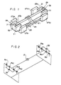
- FIG. 1 an iron core 23 is fitted through the middle of a bobbin 22 (Fig. 3) on which an electromagnetic coil 21 is wound.
- the two ends 23a and 23b of this iron core 23 project out from the ends of the bobbin 22.
- a yoke member 24 is provided below the bobbin 22 (which in fact is fixed thereto although this is not shown in the figures) and the two ends of this yoke member 24 turn upwards as shown in Fig. 1, each being formed in two pole pieces 27a1, 27a2 and 27b1, 27b2.
- the two pole pieces 27a1 and 27a2 are positioned on opposite sides of the end 23a of the iron core 23 with gaps therebetween, and similarly the other two pole pieces 27b1 and 27b2 are on opposite sides of the other end 23b of the iron core 23 with gaps therebetween.
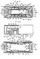
- the entire integrally fixed assembly of the coil 21, the bobbin 22, the iron core 23, and the yoke member 24 is fixed to a base 28 of the relay, best seen in Fig. 4 which is a sectional view of Fig. 3 along a plane shown by the arrows A-A in Fig. 3.
- Two armature pieces 29 are each made up by two plate iron members 31 being fixed on opposite ends which define opposite poles of a plate shaped permanent magnet 32, in a generally C-shaped configuration, so that one of the plate members 31 is magnetized to be a north pole and the other is magnetized to be a south pole.
- Each of these two armature pieces 29 is fixed to one of the ends of an actuating and connecting member 30 (see Fig. 5), and projects downwards therefrom, with each of the plate iron members 31 being inserted into one of the gaps between one side of one end of the iron core 23 and one of the pole pieces 27 of the yoke 24, as best shown in Fig. 1.
- the actuating and connecting member 30 can move in the direction transverse to the longitudinal axis of the coil 21 and the iron core 23.
- the armature pieces 29 are fixed to the actuating and connecting member 30 with the poles of their permanent magnets 32 oriented in opposite directions.
- Fig. 2 shows an equivalent magnetic circuit for this construction: in this figure, the magnetic resistances of the gaps between the ends of the iron core 23 and the pole pieces 27 of the yoke member 24 and the iron members 31 are denoted by Ra1 through Ra4 and Rb1 through Rb4.
- the electromagnetic relay construction shown can be applied either to a monostable type relay or to a latching type relay.
- sheet springs 47 (two on each side) are interposed between the sides of the actuating and connecting member 30 and rising portions 46 of the sides of the base 28 of the relay, with the one ends of the springs 47 fixed to said sides of said actuating and connecting member 30 by rivets or the like.
- Contacts are provided for being opened and closed by the movement of the actuating and connecting member 30, as follows.
- Contact chambers 35 are provided on both sides of the bobbin 22, being defined and protected by side walls 33 and end walls 34 attached to the base 28, and along the center line of each of these chambers 35 there are provided, in order, an A contact 40 extending as an A terminal 38 near its one end, a common contact 37 extending as a common terminal 36 near its center, and a B contact 41 extending as a B terminal 39 near its other end.
- Terminals 48 are power supply terminals to the coil 21.
- Two contact pieces 42 are fixed along each side of the under side of the actuating and connecting member 30 by fixing members 43. These contact pieces 42 lie in the chambers 35 and are somewhat springy. In each chamber 35 one of the contact pieces 42 extends along from the A contact 40 to the common contact 37, and the other one of the contact pieces 42 along from the common contact 37 to the B contact 41.
- each of the B terminals 39 of the electromagnetic relay is electrically connected to its corresponding common terminal 36 via the B contact 41, the corresponding contact pieces 42 and the common contact 37 whereas the A terminals 38 are disconnected from the common terminals 36.
- the actuating and connecting member 30 is shifted in the downward direction in Fig. 5 it is the A terminals 38 which are electrically connected to their corresponding common terminals 36, and the B terminals 39 which are disconnected from the corresponding common terminals 38.
- the relay is in fact to be a monostable type relay the sheet springs 47 on one side of the actuating and connecting member 30 are made weaker than those on the other side so that the actuating and connecting member 30 is biased to one side.
- each of the B-terminals 39 for instance, is electrically connected to its corresponding common terminal 36 whereas the A terminals 38 are disconnected therefrom.
- This situation is shown in Fig. 3.
- the coil 21 is so energized that a north pole is developed in the core on the right hand side of Fig. 3 and a south pole is developed on the left hand side of Fig.
- the armature pieces 29 are repelled downwards in the figure, thus moving the actuating and connecting member 30 smoothly and straight downwards by overcoming the spring action of the sheet springs 47 so as to disconnect the B terminals 39 from the common terminal 36 and simultaneously to connect the A terminals 38 to these common terminals 36.
- the action of the sheet springs 47 restores the actuating and connecting member 30 and the armature pieces 29 mounted thereon to their original upwards displaced positions (Fig.
- the sheet springs 47 on both of the sides of the actuating and connecting member 30 are made of roughly the same strength.
- the sheet springs 47 are arranged to be weaker than in the case described above, so that, when the coil 21 is not energized, the actuating and connecting member 30 is positioned in one position or the other, either upwards or downwards, according as to which way the coil 21 was last energized. From this state, if the coil 21 is energized in such a direction that a repellantforce is generated for the iron plates 31 contacting the end poles 23a, 23b of the core 23 at this time the actuating and connecting member 30 will move to its opposite position.
- the action of the relay is that of a flip- flop device in this case.
Landscapes
- Physics & Mathematics (AREA)
- Electromagnetism (AREA)
- Electromagnets (AREA)
- Interface Circuits In Exchanges (AREA)
- Burglar Alarm Systems (AREA)
- Relay Circuits (AREA)
- Steering Control In Accordance With Driving Conditions (AREA)
- Measuring Pulse, Heart Rate, Blood Pressure Or Blood Flow (AREA)
Claims (5)
dadurch gekennzeichnet,
Applications Claiming Priority (8)
| Application Number | Priority Date | Filing Date | Title |
|---|---|---|---|
| JP1983064888U JPS59171314U (ja) | 1983-04-28 | 1983-04-28 | 電磁石装置 |
| JP64888/83U | 1983-04-28 | ||
| JP126061/83U | 1983-08-12 | ||
| JP1983126061U JPS6033732U (ja) | 1983-08-12 | 1983-08-12 | 高周波リレ− |
| JP58187232A JPS6079633A (ja) | 1983-10-05 | 1983-10-05 | 電磁継電器 |
| JP187232/83 | 1983-10-05 | ||
| JP58188925A JPS6081724A (ja) | 1983-10-08 | 1983-10-08 | 電磁継電器 |
| JP188925/83 | 1983-10-08 |
Related Child Applications (6)
| Application Number | Title | Priority Date | Filing Date |
|---|---|---|---|
| EP89109083A Division EP0334393A3 (de) | 1983-04-28 | 1984-04-27 | Elektromagnetisches Relais mit symetrischer Rückwirkung |
| EP87107171A Division EP0262297A3 (de) | 1983-10-05 | 1984-04-27 | Schaltvorrichtung |
| EP87107219.5 Division-Into | 1987-05-18 | ||
| EP87107171.8 Division-Into | 1987-05-18 | ||
| EP87107218.7 Division-Into | 1987-05-18 | ||
| EP87107220.3 Division-Into | 1987-05-18 |
Publications (3)
| Publication Number | Publication Date |
|---|---|
| EP0124109A2 EP0124109A2 (de) | 1984-11-07 |
| EP0124109A3 EP0124109A3 (en) | 1985-07-10 |
| EP0124109B1 true EP0124109B1 (de) | 1989-11-29 |
Family
ID=27464500
Family Applications (2)
| Application Number | Title | Priority Date | Filing Date |
|---|---|---|---|
| EP89109083A Withdrawn EP0334393A3 (de) | 1983-04-28 | 1984-04-27 | Elektromagnetisches Relais mit symetrischer Rückwirkung |
| EP84104772A Expired EP0124109B1 (de) | 1983-04-28 | 1984-04-27 | Elektro-magnetisches Relais mit symmetrischer Rückwirkung |
Family Applications Before (1)
| Application Number | Title | Priority Date | Filing Date |
|---|---|---|---|
| EP89109083A Withdrawn EP0334393A3 (de) | 1983-04-28 | 1984-04-27 | Elektromagnetisches Relais mit symetrischer Rückwirkung |
Country Status (3)
| Country | Link |
|---|---|
| EP (2) | EP0334393A3 (de) |
| AT (1) | ATE48337T1 (de) |
| DE (1) | DE3480625D1 (de) |
Families Citing this family (10)
| Publication number | Priority date | Publication date | Assignee | Title |
|---|---|---|---|---|
| EP0130423A3 (de) * | 1983-06-30 | 1985-09-18 | EURO-Matsushita Electric Works Aktiengesellschaft | Polarisierter Elektromagnet und seine Anwendung in einem polarisierten elektromagnetischen Relais |
| DE3476604D1 (en) * | 1984-12-05 | 1989-03-09 | Sauer Hans | Relay for high-frequency circuits |
| US4613840A (en) * | 1984-12-14 | 1986-09-23 | Matsushita Electric Works, Ltd. | Relay for high-frequency circuits |
| US4713638A (en) * | 1985-10-25 | 1987-12-15 | Nec Corporation | Polarized electromagnetic relay |
| US4740771A (en) * | 1986-08-26 | 1988-04-26 | Matsushita Electric Works, Ltd. | Armature biasing means in an electromagnetic relay |
| DE68927238T2 (de) * | 1988-04-07 | 1997-05-22 | Omron Tateisi Electronics Co | Elektromagnetisches Relais |
| US5025237A (en) * | 1988-09-28 | 1991-06-18 | Anritsu Corporation | Relay device for switching radio frequency signal |
| EP0918346B1 (de) * | 1996-08-09 | 2006-02-08 | Omron Corporation | Hochfrequenzschalter |
| DE10035173C1 (de) * | 2000-07-19 | 2002-05-08 | Matsushita Electric Works Europe Ag | Magnetsystem für ein elektromagnetisches Relais |
| BE1026729B1 (de) * | 2018-10-26 | 2020-05-28 | Phoenix Contact Gmbh & Co | Wickelvorrichtung zum Wickeln von Spulendraht für ein Relais |
Family Cites Families (2)
| Publication number | Priority date | Publication date | Assignee | Title |
|---|---|---|---|---|
| DE2461884C3 (de) * | 1974-12-30 | 1982-04-15 | Sds-Elektro Gmbh, 8024 Deisenhofen | Elektromagnetisches Schaltgerät |
| US4563663A (en) * | 1982-07-16 | 1986-01-07 | Fujisoku Electric Co. Ltd. | Core member for an electromagnetic relay |
-
1984
- 1984-04-27 AT AT84104772T patent/ATE48337T1/de not_active IP Right Cessation
- 1984-04-27 EP EP89109083A patent/EP0334393A3/de not_active Withdrawn
- 1984-04-27 DE DE8484104772T patent/DE3480625D1/de not_active Expired - Lifetime
- 1984-04-27 EP EP84104772A patent/EP0124109B1/de not_active Expired
Also Published As
| Publication number | Publication date |
|---|---|
| EP0334393A3 (de) | 1989-12-13 |
| EP0124109A3 (en) | 1985-07-10 |
| EP0334393A2 (de) | 1989-09-27 |
| DE3480625D1 (de) | 1990-01-04 |
| EP0124109A2 (de) | 1984-11-07 |
| ATE48337T1 (de) | 1989-12-15 |
Similar Documents
| Publication | Publication Date | Title |
|---|---|---|
| US9275815B2 (en) | Relay having two switches that can be actuated in opposite directions | |
| EP0196022B2 (de) | Polarisierte elektromagnetische Betätigungsvorrichtung | |
| EP2673793B1 (de) | Bistabiles elektromagnetisches relais mit einem x-drive-motor | |
| US4727344A (en) | Electromagnetic drive and polarized relay | |
| US4563663A (en) | Core member for an electromagnetic relay | |
| US4688010A (en) | Electromagnetic relay | |
| US4626813A (en) | Electromagnetic drive and polarized relay | |
| US4538126A (en) | Electromagnetic relay with symmetric reaction | |
| JPH08180785A (ja) | 電磁継電器 | |
| EP0334393A2 (de) | Elektromagnetisches Relais mit symetrischer Rückwirkung | |
| EP0024216B1 (de) | Elektromagnetisches Umschalt-Relais | |
| EP0360271B1 (de) | Polarisiertes elektromagnetisches Relais | |
| US4482875A (en) | Polarized electromagnetic midget relay | |
| EP0169542B1 (de) | Polarisiertes elektromagnetisches Relais | |
| EP0157029A1 (de) | Elektromagnetischer Antrieb und polarisiertes Relais | |
| EP0127309B2 (de) | Monostabiles Relais | |
| EP0094086B1 (de) | Elektromagnetisches Relais | |
| JPH05174691A (ja) | シーソーバランス型有極継電器 | |
| JP2681820B2 (ja) | 高周波リレー | |
| EP0262297A2 (de) | Schaltvorrichtung | |
| JPH09293443A (ja) | 有極リレー | |
| JPH0440251Y2 (de) | ||
| JPH0676720A (ja) | リレーの構造 | |
| JPH0612960A (ja) | 電磁継電器 | |
| JP2630098B2 (ja) | シーソーバランス型有極継電器 |
Legal Events
| Date | Code | Title | Description |
|---|---|---|---|
| PUAI | Public reference made under article 153(3) epc to a published international application that has entered the european phase |
Free format text: ORIGINAL CODE: 0009012 |
|
| 17P | Request for examination filed |
Effective date: 19840427 |
|
| AK | Designated contracting states |
Designated state(s): AT BE CH DE FR GB IT LI LU NL SE |
|
| PUAL | Search report despatched |
Free format text: ORIGINAL CODE: 0009013 |
|
| AK | Designated contracting states |
Designated state(s): AT BE CH DE FR GB IT LI LU NL SE |
|
| 17Q | First examination report despatched |
Effective date: 19860710 |
|
| GRAA | (expected) grant |
Free format text: ORIGINAL CODE: 0009210 |
|
| AK | Designated contracting states |
Kind code of ref document: B1 Designated state(s): AT BE CH DE FR GB IT LI LU NL SE |
|
| PG25 | Lapsed in a contracting state [announced via postgrant information from national office to epo] |
Ref country code: BE Effective date: 19891129 Ref country code: NL Effective date: 19891129 Ref country code: CH Effective date: 19891129 Ref country code: SE Effective date: 19891129 Ref country code: AT Effective date: 19891129 Ref country code: LI Effective date: 19891129 |
|
| REF | Corresponds to: |
Ref document number: 48337 Country of ref document: AT Date of ref document: 19891215 Kind code of ref document: T |
|
| REF | Corresponds to: |
Ref document number: 3480625 Country of ref document: DE Date of ref document: 19900104 |
|
| ET | Fr: translation filed | ||
| ITF | It: translation for a ep patent filed | ||
| REG | Reference to a national code |
Ref country code: CH Ref legal event code: PL |
|
| PG25 | Lapsed in a contracting state [announced via postgrant information from national office to epo] |
Ref country code: LU Free format text: LAPSE BECAUSE OF NON-PAYMENT OF DUE FEES Effective date: 19900430 |
|
| NLV1 | Nl: lapsed or annulled due to failure to fulfill the requirements of art. 29p and 29m of the patents act | ||
| PLBE | No opposition filed within time limit |
Free format text: ORIGINAL CODE: 0009261 |
|
| PLBE | No opposition filed within time limit |
Free format text: ORIGINAL CODE: 0009261 |
|
| STAA | Information on the status of an ep patent application or granted ep patent |
Free format text: STATUS: NO OPPOSITION FILED WITHIN TIME LIMIT |
|
| 26N | No opposition filed | ||
| 26N | No opposition filed | ||
| REG | Reference to a national code |
Ref country code: GB Ref legal event code: 746 Effective date: 19970516 |
|
| ITPR | It: changes in ownership of a european patent |
Owner name: OFFERTA DI LICENZA AL PUBBLICO;AL PUBBLICO |
|
| REG | Reference to a national code |
Ref country code: FR Ref legal event code: D6 |
|
| PGFP | Annual fee paid to national office [announced via postgrant information from national office to epo] |
Ref country code: GB Payment date: 19980318 Year of fee payment: 15 |
|
| PG25 | Lapsed in a contracting state [announced via postgrant information from national office to epo] |
Ref country code: GB Free format text: LAPSE BECAUSE OF NON-PAYMENT OF DUE FEES Effective date: 19990427 |
|
| GBPC | Gb: european patent ceased through non-payment of renewal fee |
Effective date: 19990427 |
|
| PGFP | Annual fee paid to national office [announced via postgrant information from national office to epo] |
Ref country code: FR Payment date: 20030411 Year of fee payment: 20 |
|
| PGFP | Annual fee paid to national office [announced via postgrant information from national office to epo] |
Ref country code: DE Payment date: 20030506 Year of fee payment: 20 |