EP0124334A2 - Automatische Katalysatorregenerierung und Schätzung der Katalysatoraktivität - Google Patents
Automatische Katalysatorregenerierung und Schätzung der Katalysatoraktivität Download PDFInfo
- Publication number
- EP0124334A2 EP0124334A2 EP84302744A EP84302744A EP0124334A2 EP 0124334 A2 EP0124334 A2 EP 0124334A2 EP 84302744 A EP84302744 A EP 84302744A EP 84302744 A EP84302744 A EP 84302744A EP 0124334 A2 EP0124334 A2 EP 0124334A2
- Authority
- EP
- European Patent Office
- Prior art keywords
- catalyst
- reactor
- selectivity
- regeneration
- concentration
- Prior art date
- Legal status (The legal status is an assumption and is not a legal conclusion. Google has not performed a legal analysis and makes no representation as to the accuracy of the status listed.)
- Granted
Links
- 239000003054 catalyst Substances 0.000 title claims abstract description 143
- 230000008929 regeneration Effects 0.000 title claims abstract description 66
- 238000011069 regeneration method Methods 0.000 title claims abstract description 66
- 238000000034 method Methods 0.000 claims abstract description 44
- HSFWRNGVRCDJHI-UHFFFAOYSA-N alpha-acetylene Natural products C#C HSFWRNGVRCDJHI-UHFFFAOYSA-N 0.000 claims abstract description 31
- 125000002534 ethynyl group Chemical group [H]C#C* 0.000 claims abstract description 31
- 239000002994 raw material Substances 0.000 claims abstract description 28
- 229910052739 hydrogen Inorganic materials 0.000 claims abstract description 16
- 239000001257 hydrogen Substances 0.000 claims abstract description 16
- 238000005984 hydrogenation reaction Methods 0.000 claims abstract description 16
- UFHFLCQGNIYNRP-UHFFFAOYSA-N Hydrogen Chemical compound [H][H] UFHFLCQGNIYNRP-UHFFFAOYSA-N 0.000 claims abstract description 15
- 230000001172 regenerating effect Effects 0.000 claims abstract description 13
- 239000004215 Carbon black (E152) Substances 0.000 claims description 20
- 229930195733 hydrocarbon Natural products 0.000 claims description 20
- 150000002430 hydrocarbons Chemical class 0.000 claims description 20
- 238000012546 transfer Methods 0.000 claims description 10
- 238000004364 calculation method Methods 0.000 claims description 5
- 230000003213 activating effect Effects 0.000 claims description 3
- 238000013459 approach Methods 0.000 claims description 3
- 238000006555 catalytic reaction Methods 0.000 claims description 2
- -1 acetylene) Chemical class 0.000 claims 1
- 238000009903 catalytic hydrogenation reaction Methods 0.000 claims 1
- VGGSQFUCUMXWEO-UHFFFAOYSA-N Ethene Chemical compound C=C VGGSQFUCUMXWEO-UHFFFAOYSA-N 0.000 abstract description 11
- 239000005977 Ethylene Substances 0.000 abstract description 11
- 150000002431 hydrogen Chemical class 0.000 abstract 1
- 239000000047 product Substances 0.000 description 11
- 239000002826 coolant Substances 0.000 description 5
- 238000001816 cooling Methods 0.000 description 5
- 238000010586 diagram Methods 0.000 description 5
- 238000013461 design Methods 0.000 description 3
- 238000004519 manufacturing process Methods 0.000 description 3
- 150000001336 alkenes Chemical class 0.000 description 2
- 238000006243 chemical reaction Methods 0.000 description 2
- 230000007423 decrease Effects 0.000 description 2
- 238000001514 detection method Methods 0.000 description 2
- 239000012535 impurity Substances 0.000 description 2
- JRZJOMJEPLMPRA-UHFFFAOYSA-N olefin Natural products CCCCCCCC=C JRZJOMJEPLMPRA-UHFFFAOYSA-N 0.000 description 2
- 238000012545 processing Methods 0.000 description 2
- 229930195735 unsaturated hydrocarbon Natural products 0.000 description 2
- OTMSDBZUPAUEDD-UHFFFAOYSA-N Ethane Chemical compound CC OTMSDBZUPAUEDD-UHFFFAOYSA-N 0.000 description 1
- 239000006227 byproduct Substances 0.000 description 1
- 238000010276 construction Methods 0.000 description 1
- 230000001276 controlling effect Effects 0.000 description 1
- 238000005336 cracking Methods 0.000 description 1
- 230000001934 delay Effects 0.000 description 1
- 230000001419 dependent effect Effects 0.000 description 1
- 230000009977 dual effect Effects 0.000 description 1
- 238000005265 energy consumption Methods 0.000 description 1
- 239000000446 fuel Substances 0.000 description 1
- 230000000977 initiatory effect Effects 0.000 description 1
- 238000012423 maintenance Methods 0.000 description 1
- 238000005259 measurement Methods 0.000 description 1
- 238000012544 monitoring process Methods 0.000 description 1
- 239000002574 poison Substances 0.000 description 1
- 231100000614 poison Toxicity 0.000 description 1
- 231100000572 poisoning Toxicity 0.000 description 1
- 230000000607 poisoning effect Effects 0.000 description 1
- 230000001105 regulatory effect Effects 0.000 description 1
- 238000007086 side reaction Methods 0.000 description 1
- 239000000126 substance Substances 0.000 description 1
- 238000010977 unit operation Methods 0.000 description 1
- 238000011144 upstream manufacturing Methods 0.000 description 1
- 239000002699 waste material Substances 0.000 description 1
Images


Classifications
-
- C—CHEMISTRY; METALLURGY
- C09—DYES; PAINTS; POLISHES; NATURAL RESINS; ADHESIVES; COMPOSITIONS NOT OTHERWISE PROVIDED FOR; APPLICATIONS OF MATERIALS NOT OTHERWISE PROVIDED FOR
- C09G—POLISHING COMPOSITIONS; SKI WAXES
- C09G1/00—Polishing compositions
- C09G1/02—Polishing compositions containing abrasives or grinding agents
-
- B—PERFORMING OPERATIONS; TRANSPORTING
- B01—PHYSICAL OR CHEMICAL PROCESSES OR APPARATUS IN GENERAL
- B01J—CHEMICAL OR PHYSICAL PROCESSES, e.g. CATALYSIS OR COLLOID CHEMISTRY; THEIR RELEVANT APPARATUS
- B01J38/00—Regeneration or reactivation of catalysts, in general
-
- B—PERFORMING OPERATIONS; TRANSPORTING
- B01—PHYSICAL OR CHEMICAL PROCESSES OR APPARATUS IN GENERAL
- B01J—CHEMICAL OR PHYSICAL PROCESSES, e.g. CATALYSIS OR COLLOID CHEMISTRY; THEIR RELEVANT APPARATUS
- B01J19/00—Chemical, physical or physico-chemical processes in general; Their relevant apparatus
- B01J19/0006—Controlling or regulating processes
-
- B—PERFORMING OPERATIONS; TRANSPORTING
- B01—PHYSICAL OR CHEMICAL PROCESSES OR APPARATUS IN GENERAL
- B01J—CHEMICAL OR PHYSICAL PROCESSES, e.g. CATALYSIS OR COLLOID CHEMISTRY; THEIR RELEVANT APPARATUS
- B01J8/00—Chemical or physical processes in general, conducted in the presence of fluids and solid particles; Apparatus for such processes
- B01J8/001—Controlling catalytic processes
-
- C—CHEMISTRY; METALLURGY
- C07—ORGANIC CHEMISTRY
- C07C—ACYCLIC OR CARBOCYCLIC COMPOUNDS
- C07C5/00—Preparation of hydrocarbons from hydrocarbons containing the same number of carbon atoms
- C07C5/02—Preparation of hydrocarbons from hydrocarbons containing the same number of carbon atoms by hydrogenation
- C07C5/08—Preparation of hydrocarbons from hydrocarbons containing the same number of carbon atoms by hydrogenation of carbon-to-carbon triple bonds
- C07C5/09—Preparation of hydrocarbons from hydrocarbons containing the same number of carbon atoms by hydrogenation of carbon-to-carbon triple bonds to carbon-to-carbon double bonds
-
- Y—GENERAL TAGGING OF NEW TECHNOLOGICAL DEVELOPMENTS; GENERAL TAGGING OF CROSS-SECTIONAL TECHNOLOGIES SPANNING OVER SEVERAL SECTIONS OF THE IPC; TECHNICAL SUBJECTS COVERED BY FORMER USPC CROSS-REFERENCE ART COLLECTIONS [XRACs] AND DIGESTS
- Y02—TECHNOLOGIES OR APPLICATIONS FOR MITIGATION OR ADAPTATION AGAINST CLIMATE CHANGE
- Y02P—CLIMATE CHANGE MITIGATION TECHNOLOGIES IN THE PRODUCTION OR PROCESSING OF GOODS
- Y02P20/00—Technologies relating to chemical industry
- Y02P20/50—Improvements relating to the production of bulk chemicals
- Y02P20/52—Improvements relating to the production of bulk chemicals using catalysts, e.g. selective catalysts
-
- Y—GENERAL TAGGING OF NEW TECHNOLOGICAL DEVELOPMENTS; GENERAL TAGGING OF CROSS-SECTIONAL TECHNOLOGIES SPANNING OVER SEVERAL SECTIONS OF THE IPC; TECHNICAL SUBJECTS COVERED BY FORMER USPC CROSS-REFERENCE ART COLLECTIONS [XRACs] AND DIGESTS
- Y02—TECHNOLOGIES OR APPLICATIONS FOR MITIGATION OR ADAPTATION AGAINST CLIMATE CHANGE
- Y02P—CLIMATE CHANGE MITIGATION TECHNOLOGIES IN THE PRODUCTION OR PROCESSING OF GOODS
- Y02P20/00—Technologies relating to chemical industry
- Y02P20/50—Improvements relating to the production of bulk chemicals
- Y02P20/584—Recycling of catalysts
-
- Y—GENERAL TAGGING OF NEW TECHNOLOGICAL DEVELOPMENTS; GENERAL TAGGING OF CROSS-SECTIONAL TECHNOLOGIES SPANNING OVER SEVERAL SECTIONS OF THE IPC; TECHNICAL SUBJECTS COVERED BY FORMER USPC CROSS-REFERENCE ART COLLECTIONS [XRACs] AND DIGESTS
- Y10—TECHNICAL SUBJECTS COVERED BY FORMER USPC
- Y10T—TECHNICAL SUBJECTS COVERED BY FORMER US CLASSIFICATION
- Y10T436/00—Chemistry: analytical and immunological testing
- Y10T436/12—Condition responsive control
Definitions
- This invention relates to automatic catalyst regeneration and catalyst selectivity estimation.
- a catalyst's selectivity decays with time because of a number of factors such as presence of impurities and their concentration in the feed stream, types of byproducts from side reactions, duration of reactor operation, etc.
- factors such as presence of impurities and their concentration in the feed stream, types of byproducts from side reactions, duration of reactor operation, etc.
- acetylene in an ethylene rich stream green oil, polymerisation of green oil on the catalyst surface, etc. occurs. These are deposited on the catalyst surface, thus reducing the surface area available for the reaction.
- acetylene hydrogenation to ethylene is reduced.
- the condition may also lead to a product which is off-specification. Therefore, after operating a reactor with fresh or regenerated catalyst for some time, the catalyst is either regenerated by passing steam through the reactor or replaced by new catalyst, whichever may be appropriate depending on the specific situation.
- catalyst is regenerated either after occurrence of a severely off-specification product or it has been scheduled by maintenance personnel on the reactor, on the basis of an elapsed period of operation or during plant shutdown.
- the reactor is normally operated with catalyst for a period longer than the recommended period between two successive regenerations and replacement by fresh catalyst. Therefore, one or more of the aforementioned three conditions may occur or, worse yet, the catalyst may be poisoned.
- the recommended period of operation between two successive catalyst regenerations is about 18 months. Continued operation without regeneration may poison the catalyst completely, thus reducing its life (normally about 5 years) and may require new catalyst.
- the present invention provides apparatus for the automatic regeneration of catalyst used in a process for obtaining a product in an exit stream of a reactor, from a raw material in a feed stream of the reactor, the reactor having regeneration means for regenerating the catalyst, the apparatus being characterised by:
- a preferred embodiment of the present invention described hereinbelow provides a method and apparatus for the automatic regeneration of catalyst in a reactor which is based on the value of the catalyst selectivity.
- the catalyst is regenerated in a timely fashion, which is important in view of the high cost of catalyst and the possibility of poisoning the catalyst beyond the point where it can be regenerated.
- the preferred method and apparatus are applicable to the automatic regeneration of catalyst in a reactor wherein selective hydrogenation of specific unsaturated hydrocarbon is conducted for its removal from an olefin rich stream.
- a standby reactor is available in the preferred apparatus for the automatic regeneration of catalyst in a primary reactor.
- the apparatus can operate regardless of the type of reactor or catalyst except for the fluidised bed type of reactor.
- the apparatus according to the first aspect of the invention may include an auxiliary reactor having fresh or regenerated catalyst used in the process, the auxiliary reactor being connected to the feed and exit streams over valves which are connected to and controlled by the control system to transfer the feed stream to the auxiliary reactor when the first mentioned reactor is undergoing regeneration of its catalyst.
- the process may be the selective hydrogenation of a specific unsaturated hydrocarbon forming the raw material, for its removal from an olefin rich stream, the first and second sensor means being operable to sense a concentration of the hydrocarbon in the feed and exit streams respectively with the first sensor means also being operable to sense a concentration of hydrogen in the feed stream, and the control system including calculator means for calculating the selectivity of the catalyst according to the relationship C H1 (C A1 - C AZ ), where C Hl is the concentration of hydrogen in the feed stream, C A1 is the concentration of hydrocarbon in the feed stream and C A2 is the concentration of hydrocarbon in the exit stream.
- a method of estimating catalyst selectivity for a hydrogenation process of a hydrocarbon in a reactor the method being characterised by:
- the invention provides a method of regenerating catalyst in a process for obtaining a product in an exit stream from a raw materal in a feed stream, the method comprising sensing the concentration of raw material in the feed stream, sensing the concentration of raw material in the exit stream and determining the selectivity of the catalyst for the specific process as a function of the difference between the feed stream concentration and the exit stream concentration for the raw material.
- apparatus for carrying out a catalytic reaction with automatic catalyst regeneration the apparatus being characterised by:
- a method of regenerating a catalyst comprising providing an auxiliary reactor connected in parallel to a main reactor, to which a process is transferred during regeneration of catalyst in the primary reactor.
- the invention may be embodied so as to provide a method of regenerating catalyst in an automatic manner using a NETWORK 90 system available from the Bailey Meter Company.
- the preferred apparatus for automatically regenerating catalyst is simple in design, rugged in construction and economical to manufacture.
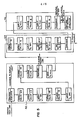
- Figure 1 shows an apparatus for automatically regenerating a catalyst in one of two reactors 10 and 110 which are of substantially identical design.
- the reactor 10 is used as a primary reactor in a process for obtaining a product from a raw material using a catalyst, with the other reactor 110 being utilised as an auxiliary reactor during the period when the catalyst in the primary reactor is being regenerated.
- the specific example illustrated involves a process for the selective hydrogenation of acetylene to ethylene.
- the invention is suitable, however, in the regeneration of catalysts in other processes.
- a feed stream containing ethylene, acetylene and hydrogen is provided over a feed line 2, past a heater 4 which, for example, uses steam and to an inlet valve 12 at an inlet of the primary reactor 10. Since the reactors 10 and 110 are substantially identical, corresponding parts in the two reactor systems are designated by the same reference numerals, except that the numerals associated with the auxiliary reactor 110 are increased by 100 with respect to those associated with the reactor 10.
- a steam line 6 is connected to the inlet of the reactor 10 and includes a regenerator valve 8.
- the line 6 is connected to a steam source 90 via a main steam valve 92 controlled by a FIC controller 94 which reacts to a computer control signal as well as a flow transmitter 96. With the valves 8 and 92 open, steam is provided to catalyst in the reactor 10 to regenerate the catalyst.
- a line connects an outlet of reactor 10 to an outlet valve 14.
- a drain valve 16 is connected to a drain line upstream of the outlet valve 14 for draining waste products of the regeneration cycle.
- An exit line 98 is connected to the outlet valve 14 of the reactor 10 as well as to the outlet valve 114 of the reactor 110.
- Each of the reactors 10, 110 comprises two reactor beds separated by an intermediate cooling bed.
- the cooling bed of the reactor 10 is connected to a cooling circuit 18 having a bypass valve 20 for regulating the temperature in the reactor 10. Coolant is supplied to a heat exchanger 24 over a coolant valve 22.
- An identical cooling circuit 118 is provided for the auxiliary reactor 110.
- a chromatograph 91 measures the concentration of acetylene and hydrogen in the feed stream of the feed line 2 and a second chromatograph 93 measures the concentration of acetylene in the exit stream of the exit line 98.
- the chromatographs 91 and 93 may be replaced by any other suitable sensor(s) for sensing raw material concentration in the feed and exit lines.
- All sensors are connected to a control computer system 50 via analog to digital converters 52.
- the steam valve controller 94 is connected over a digital to analog converter 54 to the control computer system 50.
- Instrumentation and control schemes for the reactors 10 and 110 are utilised for modulating the sytems, as well as for startup and shutdown operations. Specific details of the operation of the separate systems are known in the art and demonstrated in the above-identified US patents.
- the primary reactor 10 is initially used for the selective hydrogenation process while the reactor 110 contains regenerated or fresh catalyst that is available for subsequent use.
- the valves 12, 22 and 14 are open while the valves 8 and 16 are closed. All of the corresponding valves (108, 112, 114, 116, and 122) in the auxiliary reactor system are closed.
- the valve 20 is active for temperature control purposes in the selective hydrogenation process, while the valve 120 is inactive.
- the valve 92 is closed since it is used for modulating control during the regeneration process.
- Acetylene and hydrogen concentration in the feed stream are provided by the chromatograph 91.
- Acetylene concentration in the exit stream is provided by the chromatograph 93.
- Signals representing these concentrations are provided to the control computer system 50 where they are processed for noise and converted to engineering units in a signal processing block 26 shown in Figure 2. This is based on known principles of signal processing.
- the signals are then provided to a selectivity calculation block 28 where the selectivity calculation is performed according to the algorithm set forth above. Details of the block 28 are shown in Figure 3, where a subtraction unit 30 takes the value of the difference between the feed and exit stream acetylene concentrations which value forms the divisor of the hydrogen concentration in a division unit 32.
- the output of the unit 32 is sent to a display block 34 as well as to a desired selectivity block 36.
- the current selectivity value for the catalyst is thus displayed to the operator by the display block 34, which may be of known design.
- the block 36 for determining whether the catalyst selectivity has fallen to a set limit value Z, are shown in Figure 4.
- the value Z is set in a limit unit 38 and is based on manufacturer's recommendation and operating experience with the particular catalyst being used.
- a signal is supplied over a form message unit 39 to a catalyst status accounting block 40.
- a signal is sent to a transfer block 42 for initiating transfer of the process from the primary reactor 10 to the auxiliary reactor 110.
- Figure 5 shows details of the transfer block 42 as well as a catalyst regeneration block 44 and a ready state block 46.
- valves in the apparatus of Figure 1 are controlled in appropriate sequence and with time delays where necessary.
- the valve 122 is first opened to supply coolant to the heat exchanger 124 in the cooling circuit 118 of the auxiliary reactor 110.
- the valve 112 is then opened to establish a flow of raw materials from the feed line 2 to the reactor 110.
- a waiting period of T1 seconds is then observed to fill the reactor 110 to an appropriate level, after which the outlet valve 114 is opened for establishing a flow of products to the exit line 98.
- the inlet valve 12 of the reactor 10 is then closed and a second waiting period of T2 seconds is observed. After this time period, which permits drainage of the primary reactor 10, the outlet valve 14 is closed.
- the coolant valve 22 is closed and a message is provided to the display 34 for the purpose of informing the operator that the initial transfer steps have been taken.
- a waiting period of T3 minutes is then observed, after which regeneration for the primary reactor 10 is commenced.
- the block 44 first opens the drain valve 16.
- the regeneration valve 8 is then opened to commence the regeneration of catalyst in the reactor 10.
- the remainder of the steps illustrated in the block 44 of Figure 5 complete the regeneration process in known fashion using the controller 94 and flow transmitter 96 further in conjunction with appropriate programming in the control computer system 50.
- a last step in the automatic regeneration system is an accounting for the total time between two successive regenerations, the total time for use of catalyst and the total number of regenerations. This is accomplished in the control block 40 which is shown in greater detail in Figure 6.
- the circuit of Figure 6 permits the operator to initiate manually a regeneration step over a block 56. Regeneration also is begun whenever the total time between successive regenerations is greater than a specified time TOTALT. Regeneration may also be initiated when the total time for usage exceeds a total specified time STIME. The number of regenerations NGEGEN is also counted in the circuitry of Figure 6 with a new catalyst being provided after a selected number of regeneration cycles SREGEN.
Landscapes
- Chemical & Material Sciences (AREA)
- Organic Chemistry (AREA)
- Chemical Kinetics & Catalysis (AREA)
- Engineering & Computer Science (AREA)
- Materials Engineering (AREA)
- Catalysts (AREA)
- Organic Low-Molecular-Weight Compounds And Preparation Thereof (AREA)
- Production Of Liquid Hydrocarbon Mixture For Refining Petroleum (AREA)
Applications Claiming Priority (2)
| Application Number | Priority Date | Filing Date | Title |
|---|---|---|---|
| US488282 | 1983-04-25 | ||
| US06/488,282 US4732737A (en) | 1983-04-25 | 1983-04-25 | Automated catalyst regeneration in a reactor |
Publications (3)
| Publication Number | Publication Date |
|---|---|
| EP0124334A2 true EP0124334A2 (de) | 1984-11-07 |
| EP0124334A3 EP0124334A3 (en) | 1986-03-05 |
| EP0124334B1 EP0124334B1 (de) | 1989-07-12 |
Family
ID=23939093
Family Applications (1)
| Application Number | Title | Priority Date | Filing Date |
|---|---|---|---|
| EP84302744A Expired EP0124334B1 (de) | 1983-04-25 | 1984-04-24 | Automatische Katalysatorregenerierung und Schätzung der Katalysatoraktivität |
Country Status (12)
| Country | Link |
|---|---|
| US (1) | US4732737A (de) |
| EP (1) | EP0124334B1 (de) |
| JP (1) | JPS59206053A (de) |
| KR (1) | KR910004077B1 (de) |
| AU (1) | AU561085B2 (de) |
| BR (1) | BR8401766A (de) |
| CA (1) | CA1211275A (de) |
| DE (1) | DE3478901D1 (de) |
| ES (2) | ES531852A0 (de) |
| HK (1) | HK89689A (de) |
| IN (1) | IN160890B (de) |
| SG (1) | SG58989G (de) |
Cited By (2)
| Publication number | Priority date | Publication date | Assignee | Title |
|---|---|---|---|---|
| EP0135357A3 (de) * | 1983-08-11 | 1986-09-03 | DAVY McKEE (LONDON) LIMITED | Reaktor |
| US6540094B1 (en) * | 1998-10-30 | 2003-04-01 | Steelcase Development Corporation | Information display system |
Families Citing this family (8)
| Publication number | Priority date | Publication date | Assignee | Title |
|---|---|---|---|---|
| ATE169130T1 (de) * | 1993-11-04 | 1998-08-15 | Siemens Ag | Verfahren und einrichtung zur dosierung eines reaktanten in ein strömungsmedium |
| US5773570A (en) | 1994-05-20 | 1998-06-30 | The Regents Of The University Of California | Vaccine compositions and methods useful in inducing immune protection against arthritogenic peptides involved in the pathogenesis of rheumatoid arthritis |
| US5849593A (en) * | 1994-11-04 | 1998-12-15 | Siemens Aktiengesellschaft | Method for metering a reagent into a flowing medium |
| US7597797B2 (en) * | 2006-01-09 | 2009-10-06 | Alliance Process Partners, Llc | System and method for on-line spalling of a coker |
| US20090277514A1 (en) * | 2008-05-09 | 2009-11-12 | D-Cok, Llc | System and method to control catalyst migration |
| KR101494229B1 (ko) * | 2013-05-01 | 2015-02-17 | 한국화학연구원 | 중간생성물의 실시간 모니터링을 통한 메탄올로부터 경질올레핀 제조용 순환유동층 공정의 효율적 운전 |
| JP2017178827A (ja) * | 2016-03-29 | 2017-10-05 | 三菱ケミカル株式会社 | エチレンの製造方法 |
| KR102922647B1 (ko) * | 2020-08-24 | 2026-02-03 | 주식회사 엘지화학 | 다중 입출구 배관을 포함하는 촉매 반응기용 헤드 및 촉매 반응기용 헤드가 적용된 촉매 반응기를 이용한 공정 시스템 |
Family Cites Families (13)
| Publication number | Priority date | Publication date | Assignee | Title |
|---|---|---|---|---|
| US2621113A (en) * | 1943-09-24 | 1952-12-09 | Universal Oil Prod Co | Apparatus for catalytic conversion of hydrocarbons |
| US2901414A (en) * | 1954-06-15 | 1959-08-25 | Kellogg M W Co | Hydrocarbon conversion system |
| US2924632A (en) * | 1957-03-06 | 1960-02-09 | Exxon Research Engineering Co | Process for controlled supply of steam to catalysts |
| US3213014A (en) * | 1962-06-14 | 1965-10-19 | Phillips Petroleum Co | Computer control of hydrocarbon conversion |
| US3656911A (en) * | 1970-06-08 | 1972-04-18 | Phillips Petroleum Co | Control system for hydrogenation reactions |
| US3707463A (en) * | 1970-12-07 | 1972-12-26 | Mobil Oil Corp | Fcc catalyst section control |
| US3839483A (en) * | 1973-01-29 | 1974-10-01 | Gulf Research Development Co | Method of controlling the hydrogenation of acetylene |
| US3972804A (en) * | 1974-10-02 | 1976-08-03 | Universal Oil Products Company | Control of hydrogen/hydrocarbon mole ratio in hydrogen-consuming process |
| US4217243A (en) * | 1976-04-30 | 1980-08-12 | Phillips Petroleum Company | Catalyst regenerator control |
| US4282084A (en) * | 1978-09-27 | 1981-08-04 | Mobil Oil Corporation | Catalytic cracking process |
| US4237093A (en) * | 1978-12-27 | 1980-12-02 | Phillips Petroleum Company | Hydrocarbon cracking |
| US4236219A (en) * | 1979-05-02 | 1980-11-25 | Phillips Petroleum Company | Temperature control of exothermic reactions |
| US4241230A (en) * | 1979-11-19 | 1980-12-23 | Mobil Oil Corporation | Control system for the selective hydrogenation of acetylene present in ethylene product streams |
-
1983
- 1983-04-25 US US06/488,282 patent/US4732737A/en not_active Expired - Fee Related
-
1984
- 1984-03-26 IN IN263/DEL/84A patent/IN160890B/en unknown
- 1984-04-16 BR BR8401766A patent/BR8401766A/pt not_active IP Right Cessation
- 1984-04-24 CA CA000452571A patent/CA1211275A/en not_active Expired
- 1984-04-24 AU AU27225/84A patent/AU561085B2/en not_active Ceased
- 1984-04-24 KR KR1019840002177A patent/KR910004077B1/ko not_active Expired
- 1984-04-24 EP EP84302744A patent/EP0124334B1/de not_active Expired
- 1984-04-24 DE DE8484302744T patent/DE3478901D1/de not_active Expired
- 1984-04-24 ES ES531852A patent/ES531852A0/es active Granted
- 1984-04-25 JP JP59082135A patent/JPS59206053A/ja active Pending
-
1985
- 1985-06-28 ES ES544687A patent/ES8706477A1/es not_active Expired
-
1989
- 1989-08-28 SG SG589/89A patent/SG58989G/en unknown
- 1989-11-09 HK HK896/89A patent/HK89689A/xx unknown
Cited By (2)
| Publication number | Priority date | Publication date | Assignee | Title |
|---|---|---|---|---|
| EP0135357A3 (de) * | 1983-08-11 | 1986-09-03 | DAVY McKEE (LONDON) LIMITED | Reaktor |
| US6540094B1 (en) * | 1998-10-30 | 2003-04-01 | Steelcase Development Corporation | Information display system |
Also Published As
| Publication number | Publication date |
|---|---|
| ES544687A0 (es) | 1987-07-01 |
| HK89689A (en) | 1989-11-17 |
| EP0124334B1 (de) | 1989-07-12 |
| AU2722584A (en) | 1984-11-01 |
| EP0124334A3 (en) | 1986-03-05 |
| ES8603094A1 (es) | 1985-12-01 |
| KR850003337A (ko) | 1985-06-17 |
| SG58989G (en) | 1989-12-29 |
| KR910004077B1 (ko) | 1991-06-22 |
| AU561085B2 (en) | 1987-04-30 |
| DE3478901D1 (en) | 1989-08-17 |
| IN160890B (de) | 1987-08-15 |
| JPS59206053A (ja) | 1984-11-21 |
| ES531852A0 (es) | 1985-12-01 |
| ES8706477A1 (es) | 1987-07-01 |
| US4732737A (en) | 1988-03-22 |
| BR8401766A (pt) | 1984-12-04 |
| CA1211275A (en) | 1986-09-16 |
Similar Documents
| Publication | Publication Date | Title |
|---|---|---|
| EP0124334B1 (de) | Automatische Katalysatorregenerierung und Schätzung der Katalysatoraktivität | |
| US3636331A (en) | Method and system for the automatic control of chemical plants with parallel-connected computer backup system | |
| US4668473A (en) | Control system for ethylene polymerization reactor | |
| US4236219A (en) | Temperature control of exothermic reactions | |
| US4347564A (en) | Hierarchical-structure plant control system | |
| US3471582A (en) | Control of exothermic reactions | |
| US3979183A (en) | Heat exchange and flow control system for series flow reactors | |
| EP0124333B1 (de) | Polymerisationsreaktorsteuerapparat | |
| JP2024522982A5 (de) | ||
| US4241230A (en) | Control system for the selective hydrogenation of acetylene present in ethylene product streams | |
| US4560815A (en) | Automated catalyst regeneration in a reactor | |
| US6239055B1 (en) | Process and vessel for regeneration of a catalyst including monitoring and monitoring and control of combustion completion | |
| CN114429791B (zh) | 多段床碳二加氢反应器的控制方法及应用 | |
| EP0109289B1 (de) | Bestimmung der effektiven Wärmeübertragung von Reaktoren | |
| US3981792A (en) | Heat exchange method for series flow reactors | |
| CN118262833A (zh) | 优化烷烃脱氢操作的方法和系统 | |
| US3663805A (en) | Method and apparatus for monitoring processes | |
| JP2002309272A (ja) | 水添反応装置の自動制御システム | |
| GB1591360A (en) | Method and apparatus for automatic change of operation in air separation plant | |
| JPS60147226A (ja) | 触媒充填管式固気接触反応装置の運転方法 | |
| RU2091361C1 (ru) | Устройство для автоматического управления реактором дегидрирования углеводородного сырья | |
| EP0294052A2 (de) | Autobeschleunigungskontrolle für exotherme Reaktoren | |
| JPH08314539A (ja) | 異常解析用データ収集方法 | |
| Schbib et al. | Dynamics and control of an industrial front-end acetylene converter | |
| US2901414A (en) | Hydrocarbon conversion system |
Legal Events
| Date | Code | Title | Description |
|---|---|---|---|
| PUAI | Public reference made under article 153(3) epc to a published international application that has entered the european phase |
Free format text: ORIGINAL CODE: 0009012 |
|
| AK | Designated contracting states |
Designated state(s): DE FR GB IT |
|
| PUAL | Search report despatched |
Free format text: ORIGINAL CODE: 0009013 |
|
| AK | Designated contracting states |
Kind code of ref document: A3 Designated state(s): DE FR GB IT |
|
| 17P | Request for examination filed |
Effective date: 19860703 |
|
| 17Q | First examination report despatched |
Effective date: 19870511 |
|
| ITF | It: translation for a ep patent filed | ||
| GRAA | (expected) grant |
Free format text: ORIGINAL CODE: 0009210 |
|
| AK | Designated contracting states |
Kind code of ref document: B1 Designated state(s): DE FR GB IT |
|
| REF | Corresponds to: |
Ref document number: 3478901 Country of ref document: DE Date of ref document: 19890817 |
|
| ET | Fr: translation filed | ||
| PLBE | No opposition filed within time limit |
Free format text: ORIGINAL CODE: 0009261 |
|
| STAA | Information on the status of an ep patent application or granted ep patent |
Free format text: STATUS: NO OPPOSITION FILED WITHIN TIME LIMIT |
|
| 26N | No opposition filed | ||
| PGFP | Annual fee paid to national office [announced via postgrant information from national office to epo] |
Ref country code: GB Payment date: 19910325 Year of fee payment: 8 |
|
| PGFP | Annual fee paid to national office [announced via postgrant information from national office to epo] |
Ref country code: FR Payment date: 19910422 Year of fee payment: 8 |
|
| PGFP | Annual fee paid to national office [announced via postgrant information from national office to epo] |
Ref country code: DE Payment date: 19910429 Year of fee payment: 8 |
|
| ITTA | It: last paid annual fee | ||
| REG | Reference to a national code |
Ref country code: GB Ref legal event code: 732 |
|
| PG25 | Lapsed in a contracting state [announced via postgrant information from national office to epo] |
Ref country code: GB Effective date: 19920424 |
|
| GBPC | Gb: european patent ceased through non-payment of renewal fee | ||
| PG25 | Lapsed in a contracting state [announced via postgrant information from national office to epo] |
Ref country code: FR Effective date: 19921230 |
|
| PG25 | Lapsed in a contracting state [announced via postgrant information from national office to epo] |
Ref country code: DE Effective date: 19930101 |
|
| REG | Reference to a national code |
Ref country code: FR Ref legal event code: ST |