EP0124361A2 - Unité de bâtiment - Google Patents
Unité de bâtiment Download PDFInfo
- Publication number
- EP0124361A2 EP0124361A2 EP84302840A EP84302840A EP0124361A2 EP 0124361 A2 EP0124361 A2 EP 0124361A2 EP 84302840 A EP84302840 A EP 84302840A EP 84302840 A EP84302840 A EP 84302840A EP 0124361 A2 EP0124361 A2 EP 0124361A2
- Authority
- EP
- European Patent Office
- Prior art keywords
- floor
- axis
- floor portion
- building unit
- closure means
- Prior art date
- Legal status (The legal status is an assumption and is not a legal conclusion. Google has not performed a legal analysis and makes no representation as to the accuracy of the status listed.)
- Withdrawn
Links
- 230000000694 effects Effects 0.000 description 2
- 239000004677 Nylon Substances 0.000 description 1
- 230000004308 accommodation Effects 0.000 description 1
- 239000011093 chipboard Substances 0.000 description 1
- 238000010438 heat treatment Methods 0.000 description 1
- 239000000463 material Substances 0.000 description 1
- 239000002184 metal Substances 0.000 description 1
- 238000000034 method Methods 0.000 description 1
- 229920001778 nylon Polymers 0.000 description 1
- 239000011120 plywood Substances 0.000 description 1
- 239000007787 solid Substances 0.000 description 1
Images


Classifications
-
- E—FIXED CONSTRUCTIONS
- E04—BUILDING
- E04B—GENERAL BUILDING CONSTRUCTIONS; WALLS, e.g. PARTITIONS; ROOFS; FLOORS; CEILINGS; INSULATION OR OTHER PROTECTION OF BUILDINGS
- E04B1/00—Constructions in general; Structures which are not restricted either to walls, e.g. partitions, or floors or ceilings or roofs
- E04B1/348—Structures composed of units comprising at least considerable parts of two sides of a room, e.g. box-like or cell-like units closed or in skeleton form
- E04B1/34815—Elements not integrated in a skeleton
-
- E—FIXED CONSTRUCTIONS
- E04—BUILDING
- E04H—BUILDINGS OR LIKE STRUCTURES FOR PARTICULAR PURPOSES; SWIMMING OR SPLASH BATHS OR POOLS; MASTS; FENCING; TENTS OR CANOPIES, IN GENERAL
- E04H1/00—Buildings or groups of buildings for dwelling or office purposes; General layout, e.g. modular co-ordination or staggered storeys
- E04H1/02—Dwelling houses; Buildings for temporary habitation, e.g. summer houses
-
- E—FIXED CONSTRUCTIONS
- E04—BUILDING
- E04B—GENERAL BUILDING CONSTRUCTIONS; WALLS, e.g. PARTITIONS; ROOFS; FLOORS; CEILINGS; INSULATION OR OTHER PROTECTION OF BUILDINGS
- E04B1/00—Constructions in general; Structures which are not restricted either to walls, e.g. partitions, or floors or ceilings or roofs
- E04B1/348—Structures composed of units comprising at least considerable parts of two sides of a room, e.g. box-like or cell-like units closed or in skeleton form
- E04B2001/34892—Means allowing access to the units, e.g. stairs or cantilevered gangways
Definitions
- This invention relates to building units, which term is used herein to include building modules, rooms or like portions of new or existing buildings, and also extensions to existing buildings.
- a domestic room module comprising fixed wall structures enclosing a lower floor and an upper floor, the said upper floor being spaced from the lower floor at a height not exceeding one-third of the height of the wall structures, the said upper floor containing a portion rotatable-upwardly on an edge about a horizontal axis to form in a horizontal position an upper floor portion of the module and in a vertical position a wall dividing the room and whereby in the vertical position a portion of the lower floor is exposed, and optionally drive means to effect the said rotation of the said rotatable upper floor portion.
- the provision of the rotatable upper floor portion enables the module to be used both as a living room and also as a bedroom, or for storage purposes.
- the invention consists in a building unit comprising fixed wall structures enclosing a lower floor and an upper floor, the said upper floor being spaced from the lower floor at a height not exceeding one third of the height of the wall structures, the said upper floor including an opening provided with closure means, said closure means comprising a first floor portion rotatable about a first axis substantially in, or parallel to, the plane of said upper floor, a second floor portion hingedly connected to said first floor portion so that it is rotatable relative thereto about a second axis parallel to said first axis, and guide means for supporting said second floor portion for sliding and tilting motion relative to said upper floor.
- the opening in the upper floor gives access to the lower floor which may be provided with bedroom furniture, storage devices, heating equipment or the like.
- the closure means of the present invention does not extend as far in the vertical direction as it does in the horizontal direction. Since it consists of two hinged portions, it effectively folds so that, when it is in the vertical position, its height is only a fraction of its length when it is in the horizontal position. It is to be understood that the invention is not restricted to the use of two floor portions for the closure means, but may extend to the use of three or more such portions which fold together in concertina fashion when access is required to the lower floor.
- counter-balance weights are provided on the first floor portion of the closure means to assist in rotating that floor portion from its horizontal to its vertical position.
- the opening is rectangular and the first axis is located at or near one of the larger ends of the rectangle.
- each of these has a length equal to the length of the rectangle and a width which is approximately half the width of the rectangle.
- the guide means comprise primarily rails located along the shorter sides of the rectangular opening. These guides support the end of the second floor portion remote from the second axis for sliding motion while the closure means is being raised or lowered.
- the counter-weight preferably consists of two relatively heavy members secured to the first floor portion so that they project in, or parallel to, the plane of the first floor portion on the side of the first axis opposite to the extent of the first floor portion.
- the edge of the opening at which the first axis is located is adjacent to a wall of the unit or to a dividing wall located within the unit.
- the wall or dividing wall is preferably constructed in such a way as to provide a space in which the first and second floor portions can be accommodated when they are in their vertical positions.
- Figure 1 illustrates the use of building units in accordance with the invention in a motel.
- the particular arrangement illustrated includes twelve units 1 in accordance with the invention, arranged above a corresponding number of garage units 2.
- the building units are arranged in two rows with an elevated passageway 3 therebetween. Steps 4 lead to this passageway which is covered by a barrel roof 5 and provides access to all twelve building units.
- Each building unit includes an entrance porch, a passage, a bathroom and toilet, a fitted kitchen, and a lounge area which provides access to a bedroom area.
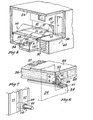
- the unit consists of a base 20, a top 21, end walls 22 and 23, side walls 24 and 25, and an intermediate floor 26. Windows 27 and 28 are provided respectively in the end walls 22 and 23, and a window 29 is provided in the side wall 25.
- the lounge area is shown at 6, the kitchen area at 7 and the bathroom and toilet at 8.
- the floor of the lounge area includes an opening provided with closure means 10.
- the closure means illustrated includes two floor portions 11 and 12 which are hingedly connected together at 13.
- the floor portion 12 is hingedly connected to the side wall 24 at 14, and to a supporting pillar 15 at 16.
- a rail 17 is mounted on the side wall 24 and a further rail 18 is carried by a beam 9 extending between the pillar 15 and a further pillar 19 ( Figure 4).
- closure 10 Secured to the righthand side of the floor portion 12 (as seen in the drawings) are two counter-weights 36 and 37, and mounted at the lefthand two corners of the floor portion 11 are two rollers 38 and 39.
- closure 10 When the closure 10 is in its horizontal position, as shown in Figures 2 and 3, it provides a part of the lounge floor and conceals the space between the upper and lower floors which contains a bed 30 and storage devices 31 and 32.
- a further removable portion 33 of the lounge floor provides access to a flight of steps 34 leading from the level of the upper floor to the level of the lower floor.
- access is provided to the free edge 35 of the floor portion 11. If a force is applied to this edge in the direction of the arrow 36 ( Figure 4), the rollers 38 and 39 will travel along the rails 17 and 18, with the result that the hinge 13 will rise as the floor portion 12 rotates about the axis of the pivots 14 and 16.
- the wall 40 separating the lounge area from the kitchen, is constructed with a recess 41 designed to receive the two floor portions 11 and 12 as they are moved to their vertical positions. Thus the two portions are accommodated in this recess as shown in chain dotted lines in Figure 3.
- FIG. 6 shows a portion of the rail 17 mounted on a platform 54 formed on the wall 24. This figure also shows the roller 39 mounted in a metal bracket 55 secured to a timber member 56 forming part of the frame of the floor portion.
- each of the floor portions consists of a timber frame and a filling of fireproof foamed material 57 enclosed between upper and lower panels 58 and 59 consisting of chipboard or plywood.
- FIG. 7 shows the pivot 14 in the wall 24.
- This pivot consists of a solid nylon bush 60 set in the wall 24, and a pin 61 fitted to the timber frame of the floor portion 12.
- the floor area of the lounge is approximately 5 metres by 3.5 metres, the area of the kitchen is 2.5 metres by 3 metres, and the bathroom and toilet is 2.5 metres by 2 metres.
- the height between the upper floor 26 and the underside of the top 21 is 2.4 metres, and the height between the upper and lower floors is 1 metre.
- the unit described is designed to accommodate two people. If it is desired to provide additional accommodation, two units may be combined, and in this case the second unit is modified by replacing the kitchen area 7 by a further bedroom area.
- This cover 33 When it is desired to use the bedroom area under the lounge 6, the cover 33 will be removed to provide access to the steps 34.
- This cover 33 may be in the form of a counter-balanced hatch which can be folded back against the wall.
- the occupant can then walk down the steps, turn 90 degrees clockwise and push back the closure means 10 until it is folded into the recess 41 of the wall 40. This will provide access to a carpeted area of two metres by 2.5 metres.
- the space on two sides under the floor 26 will have a number of storage drawers.
- the bed 30 will be stored under the kitchen area. It is mounted on six wheels 63 which run on rails 64. Accordingly the bed can be pulled from its storage position shown in full lines in Figure 3 to the night position, shown in broken lines.
Landscapes
- Engineering & Computer Science (AREA)
- Architecture (AREA)
- Civil Engineering (AREA)
- Structural Engineering (AREA)
- Physics & Mathematics (AREA)
- Electromagnetism (AREA)
- Floor Finish (AREA)
- Specific Sealing Or Ventilating Devices For Doors And Windows (AREA)
- Building Environments (AREA)
- Hinges (AREA)
- Residential Or Office Buildings (AREA)
Applications Claiming Priority (2)
| Application Number | Priority Date | Filing Date | Title |
|---|---|---|---|
| GB8311864 | 1983-04-29 | ||
| GB838311864A GB8311864D0 (en) | 1983-04-29 | 1983-04-29 | Building units |
Publications (2)
| Publication Number | Publication Date |
|---|---|
| EP0124361A2 true EP0124361A2 (fr) | 1984-11-07 |
| EP0124361A3 EP0124361A3 (fr) | 1986-10-29 |
Family
ID=10541961
Family Applications (1)
| Application Number | Title | Priority Date | Filing Date |
|---|---|---|---|
| EP84302840A Withdrawn EP0124361A3 (fr) | 1983-04-29 | 1984-04-27 | Unité de bâtiment |
Country Status (2)
| Country | Link |
|---|---|
| EP (1) | EP0124361A3 (fr) |
| GB (2) | GB8311864D0 (fr) |
Cited By (1)
| Publication number | Priority date | Publication date | Assignee | Title |
|---|---|---|---|---|
| AT413404B (de) * | 2002-05-15 | 2006-02-15 | Kaeferhaus Jochen | Bauwerk, insbesondere wohnhaus |
Families Citing this family (2)
| Publication number | Priority date | Publication date | Assignee | Title |
|---|---|---|---|---|
| GB2187772A (en) * | 1986-03-15 | 1987-09-16 | Victor Ryder Keeling | Temporary floor over swimming pool |
| GB2205535B (en) * | 1987-06-10 | 1991-08-14 | Richard Frank Harris | Vehicle having sleeping arrangements |
Family Cites Families (4)
| Publication number | Priority date | Publication date | Assignee | Title |
|---|---|---|---|---|
| US1494273A (en) * | 1922-09-11 | 1924-05-13 | Peter E Moran | Trap grain door |
| CH490598A (de) * | 1967-12-06 | 1970-05-15 | Troesch Louis | Mehrzweckraum |
| ES438556A1 (es) * | 1974-06-20 | 1977-08-16 | Ghionda Andre | Perfeccionamientos introducidos en elementos permutables a- plicables a habitaciones. |
| GB1528743A (en) * | 1974-10-23 | 1978-10-18 | Vagabond Films Ets | Building modules |
-
1983
- 1983-04-29 GB GB838311864A patent/GB8311864D0/en active Pending
-
1984
- 1984-04-27 EP EP84302840A patent/EP0124361A3/fr not_active Withdrawn
- 1984-04-27 GB GB08410793A patent/GB2139265A/en not_active Withdrawn
Cited By (1)
| Publication number | Priority date | Publication date | Assignee | Title |
|---|---|---|---|---|
| AT413404B (de) * | 2002-05-15 | 2006-02-15 | Kaeferhaus Jochen | Bauwerk, insbesondere wohnhaus |
Also Published As
| Publication number | Publication date |
|---|---|
| GB2139265A (en) | 1984-11-07 |
| EP0124361A3 (fr) | 1986-10-29 |
| GB8410793D0 (en) | 1984-06-06 |
| GB8311864D0 (en) | 1983-06-02 |
Similar Documents
| Publication | Publication Date | Title |
|---|---|---|
| US6676233B1 (en) | Storage lift | |
| RU2083772C1 (ru) | Транспортабельная трансформируемая строительная конструкция | |
| US5732839A (en) | Container | |
| CA1204911A (fr) | Maison pliante | |
| AU652212B2 (en) | Floor-supported movable wall panel | |
| US4378043A (en) | Pivoting screen panel for sectional garage door | |
| EP0097475A1 (fr) | Structure de bâtiment préfabriqué transportable | |
| CA2064348C (fr) | Cloisons murales demontables verticalement | |
| JPS62502415A (ja) | 伸縮可能な構造物 | |
| US5363520A (en) | Space-saving bed | |
| EP0225675B1 (fr) | Unité de base pour le montage d'une porte coulissante | |
| US5103934A (en) | Method and apparatus for providing a fire escape for a multi-story building | |
| EP0065398A1 (fr) | Constructions comprenant de parois coulissantes dans leur plan | |
| US2780843A (en) | Expansible building enclosure | |
| US4381046A (en) | Fire escape ladder storage and deployment device | |
| US4609027A (en) | Overhead door | |
| EP0124361A2 (fr) | Unité de bâtiment | |
| US3467460A (en) | Retractable clothes storage apparatus | |
| US4922666A (en) | Porch with recessible windows | |
| US3100915A (en) | Walk-in stairwell closet | |
| CN102057125A (zh) | 用于阳台的屏障组件 | |
| US20060000675A1 (en) | Platform lift apparatus for attic storage space | |
| CA1326171C (fr) | Fenetre munie d'une traverse amovible | |
| EP0135987A2 (fr) | Moyen d'assemblage entre un plancher et un mur | |
| GB2391022A (en) | Transportable buildings which can interlink |
Legal Events
| Date | Code | Title | Description |
|---|---|---|---|
| PUAI | Public reference made under article 153(3) epc to a published international application that has entered the european phase |
Free format text: ORIGINAL CODE: 0009012 |
|
| AK | Designated contracting states |
Designated state(s): DE FR SE |
|
| PUAL | Search report despatched |
Free format text: ORIGINAL CODE: 0009013 |
|
| AK | Designated contracting states |
Kind code of ref document: A3 Designated state(s): DE FR SE |
|
| STAA | Information on the status of an ep patent application or granted ep patent |
Free format text: STATUS: THE APPLICATION IS DEEMED TO BE WITHDRAWN |
|
| 18D | Application deemed to be withdrawn |
Effective date: 19861031 |
|
| RIN1 | Information on inventor provided before grant (corrected) |
Inventor name: LEWIS, THOMAS MALDWYN |