EP0124504A1 - Dispositif d'arrêt d'un moteur à combustion interne à injection de combustible - Google Patents
Dispositif d'arrêt d'un moteur à combustion interne à injection de combustible Download PDFInfo
- Publication number
- EP0124504A1 EP0124504A1 EP84890057A EP84890057A EP0124504A1 EP 0124504 A1 EP0124504 A1 EP 0124504A1 EP 84890057 A EP84890057 A EP 84890057A EP 84890057 A EP84890057 A EP 84890057A EP 0124504 A1 EP0124504 A1 EP 0124504A1
- Authority
- EP
- European Patent Office
- Prior art keywords
- tank
- line
- pump
- valve
- suction chamber
- Prior art date
- Legal status (The legal status is an assumption and is not a legal conclusion. Google has not performed a legal analysis and makes no representation as to the accuracy of the status listed.)
- Ceased
Links
- 238000002347 injection Methods 0.000 title claims abstract description 30
- 239000007924 injection Substances 0.000 title claims abstract description 30
- 238000002485 combustion reaction Methods 0.000 title claims abstract description 7
- 239000000446 fuel Substances 0.000 claims description 19
- 239000002283 diesel fuel Substances 0.000 claims description 2
- 239000002828 fuel tank Substances 0.000 description 3
- 238000010276 construction Methods 0.000 description 2
- 238000000034 method Methods 0.000 description 1
- 230000000717 retained effect Effects 0.000 description 1
Images
Classifications
-
- F—MECHANICAL ENGINEERING; LIGHTING; HEATING; WEAPONS; BLASTING
- F02—COMBUSTION ENGINES; HOT-GAS OR COMBUSTION-PRODUCT ENGINE PLANTS
- F02M—SUPPLYING COMBUSTION ENGINES IN GENERAL WITH COMBUSTIBLE MIXTURES OR CONSTITUENTS THEREOF
- F02M63/00—Other fuel-injection apparatus having pertinent characteristics not provided for in groups F02M39/00 - F02M57/00 or F02M67/00; Details, component parts, or accessories of fuel-injection apparatus, not provided for in, or of interest apart from, the apparatus of groups F02M39/00 - F02M61/00 or F02M67/00; Combination of fuel pump with other devices, e.g. lubricating oil pump
- F02M63/02—Fuel-injection apparatus having several injectors fed by a common pumping element, or having several pumping elements feeding a common injector; Fuel-injection apparatus having provisions for cutting-out pumps, pumping elements, or injectors; Fuel-injection apparatus having provisions for variably interconnecting pumping elements and injectors alternatively
- F02M63/0205—Fuel-injection apparatus having several injectors fed by a common pumping element, or having several pumping elements feeding a common injector; Fuel-injection apparatus having provisions for cutting-out pumps, pumping elements, or injectors; Fuel-injection apparatus having provisions for variably interconnecting pumping elements and injectors alternatively for cutting-out pumps or injectors in case of abnormal operation of the engine or the injection apparatus, e.g. over-speed, break-down of fuel pumps or injectors ; for cutting-out pumps for stopping the engine
- F02M63/0215—Fuel-injection apparatus having several injectors fed by a common pumping element, or having several pumping elements feeding a common injector; Fuel-injection apparatus having provisions for cutting-out pumps, pumping elements, or injectors; Fuel-injection apparatus having provisions for variably interconnecting pumping elements and injectors alternatively for cutting-out pumps or injectors in case of abnormal operation of the engine or the injection apparatus, e.g. over-speed, break-down of fuel pumps or injectors ; for cutting-out pumps for stopping the engine by draining or closing fuel conduits
Definitions
- the invention relates to a device for switching off an injection internal combustion engine, in which fuel, in particular diesel fuel, is supplied from a tank via a backing pump and at least one fuel filter to the suction chamber of an injection pump, with at least one switched into the delivery line from the tank and to the suction chamber of the injection pump Reversing valve and an overflow line from the suction chamber of the injection pump to the tank, in which line a pressure control valve is switched on.
- fuel in particular diesel fuel
- a reversing valve is arranged in the delivery line to the suction chamber of the injection pump.
- the suction chamber of the injection pump is in turn connected to the tank via an overflow valve.
- the reversing valve is actuated electromagnetically and the direction of flow of the medium in the delivery line from the tank to the suction chamber of the pump is reversed by switching the lines in front of the input of the backing pump to switch off the injection internal combustion engine.
- the backing pump thus sucks the suction space of the injection pump empty, the delivery line to the suction space now being connected as a suction line to the tank.
- a suction of fuel from the tank via the overflow line is prevented by the overflow valve, which is designed as a pressure maintaining valve and closes in the direction of the suction chamber of the injection pump. Due to the reversal of the flow direction and thus the fuel column in the delivery lines, such an arrangement responds only with a delay to the actuation of the reversing valve.
- the invention now aims to increase the response speed of such an arrangement and to make the shutdown dynamics independent of the design of the overflow valve. Even the construction of the Overflow valves have an influence on the timing of the function of the shutdown process.
- the invention consists essentially in that the reversing valve (s) in the delivery line and the overflow line is (are), in the operating position the suction side of the backing pump with the tank and the pressure side of the backing pump via the delivery line is connected to the suction chamber of the injection pump, and in the switch-off position the suction side of the backing pump is connected to the overflow line from the suction chamber of the injection pump and the pressure side of the backing pump is connected to the overflow line to the tank.
- the reversing valve is not only switched on in the delivery line, but is also switched on in the overflow line, there is the possibility of controlling these valves in such a way that in the event of a reversing pulse, in particular when the valves are actuated electromagnetically, the direction of flow through the suction chamber and by means of the lines leading to the suction space and leading away from the suction space. This is achieved in that in the operating position the suction side of the backing pump is connected to the tank and the pressure side of the backing pump is connected to the suction chamber of the injection pump via the delivery line.
- both valves are switched over and the suction side of the backing pump is connected to the overflow line from the suction chamber of the injection pump and the pressure side of the backing pump is connected to the overflow line to the tank.
- the direction of flow in the lines thus remains the same and the suction chamber of the injection pump is flowed through in the same sense in both positions, so that the inertia of the response is significantly reduced.
- a further reduction in the response delay can be achieved in that the reversing valve switched on in the delivery line in the switch-off position Bypasses the pressure side of the backing pump bypassing the pressure control valve or overflow valve directly to the tank.
- the reversing valve is designed as a multi-way valve common to both lines and is switched on in the delivery line and the overflow line.
- the two-way multi-way valve is preferably designed as a 6/5 way valve.
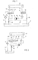
- FIG. 1 shows an embodiment with two separate valves in the delivery line and in the overflow line
- FIG. 2 shows an embodiment with a valve common to both lines.
- Fig.l 1 denotes the fuel tank.
- a feed pump or backing pump 2 sucks in the fuel via a line 3 with the interposition of a fuel filter 4 and delivers the fuel via a first reversing valve 5 through a second fuel filter 6 and a line 7 to the suction chamber 8 of the injection pump of the internal combustion engine.
- Another reversing valve 9 is switched on in line 7.
- Lines 3 and 7 result in the delivery line to suction chamber 8 of the injection pump.
- the fuel filters 4 and 6 can be designed as prefilters and fine filters.
- the pressure in the suction chamber 8 is built up by a pressure holding valve 10 in the overflow line 9.
- the electromagnetically actuated reversing valve 5 is also switched on.
- the valves are drawn in the operating state.
- both the valve 5 and the valve 9 are switched off by switching off the power supply the force of the springs 11 and 12 switched.
- the valve bodies of valves 5 and 9 are shifted to the left.
- the backing pump 2 sucks fuel out of the suction space of the injection pump via the first partial region of the overflow line 9, the direction of flow in the direction of arrow 13 being identical to the direction of flow in the operating state.
- the extracted fuel passes through lines 14 and 15 as well as the fuel filter 6 and the second valve 9 into a further line 16 and thus back into the tank.
- the fuel can also be returned to the tank, as indicated by the dashed line 17, via a line into the original second part of the overflow line 9 before or after the overflow valve or pressure control valve 10.
- the reversing valve 5 is designed as a 4/3-way valve and the reversing valve 9 as a 3/2-way valve.
- the fuel tank or the tank is again designated 1.
- the fuel from this tank is in turn sucked in via a suction line 3 and a first fuel filter 4 by the backing pump 2 and passes through a further filter 6 with the interposition of the reversing valve 18 into the delivery line 7 to the suction chamber 8 of the injection pump.
- the pressure is in turn built up by the pressure holding valve 10, which is switched on in the overflow line 9.
- the changeover valve 18 is located both in the overflow line 9 and in the delivery line 7 from or to the suction chamber 8 of the injection pump.
- the switch-off takes place in turn by the force of the spring 19, which shifts the valve body of the reversing valve 18 to the left.
- the overflow line 9 is connected to the suction side of the backing pump 2, so that the original flow direction 5, which is symbolized by the arrow 13, is again retained here.
- the fuel sucked out of the suction chamber 8 is by the Backing pump 2 is conveyed via the fuel filter and the now switched reversing valve 18 into the overflow line 9 and is pressed into the tank or fuel tank 1 via the pressure holding valve 10.
Landscapes
- Engineering & Computer Science (AREA)
- Chemical & Material Sciences (AREA)
- Combustion & Propulsion (AREA)
- Mechanical Engineering (AREA)
- General Engineering & Computer Science (AREA)
- Fuel-Injection Apparatus (AREA)
Applications Claiming Priority (2)
| Application Number | Priority Date | Filing Date | Title |
|---|---|---|---|
| AT1065/83 | 1983-03-25 | ||
| AT106583 | 1983-03-25 |
Publications (1)
| Publication Number | Publication Date |
|---|---|
| EP0124504A1 true EP0124504A1 (fr) | 1984-11-07 |
Family
ID=3505837
Family Applications (1)
| Application Number | Title | Priority Date | Filing Date |
|---|---|---|---|
| EP84890057A Ceased EP0124504A1 (fr) | 1983-03-25 | 1984-03-23 | Dispositif d'arrêt d'un moteur à combustion interne à injection de combustible |
Country Status (1)
| Country | Link |
|---|---|
| EP (1) | EP0124504A1 (fr) |
Cited By (5)
| Publication number | Priority date | Publication date | Assignee | Title |
|---|---|---|---|---|
| DE3705972A1 (de) * | 1987-02-25 | 1988-09-08 | Audi Ag | Steuereinrichtung fuer eine diesel-brennkraftmaschine |
| DE3718714A1 (de) * | 1986-01-22 | 1988-12-22 | Kloeckner Humboldt Deutz Ag | Vorrichtung zur anhebung des verbrennungstemperaturniveaus in einer brennkraftmaschine |
| DE4136626C1 (fr) * | 1991-11-07 | 1992-10-08 | Mercedes-Benz Aktiengesellschaft, 7000 Stuttgart, De | |
| US5832900A (en) * | 1998-04-23 | 1998-11-10 | Siemens Automotove Corporation | Fuel recirculation arrangement and method for direct fuel injection system |
| DE4104791B4 (de) * | 1991-02-16 | 2004-04-01 | Robert Bosch Gmbh | Vorrichtung zur Abschaltung einzelner Zylinder einer Brennkraftmaschine |
Citations (2)
| Publication number | Priority date | Publication date | Assignee | Title |
|---|---|---|---|---|
| GB2074658A (en) * | 1980-04-17 | 1981-11-04 | Bosch Gmbh Robert | Fuel injection system for diesel internal combustion engines |
| US4319550A (en) * | 1979-05-11 | 1982-03-16 | Nippondenso Co., Ltd. | Engine stop apparatus |
-
1984
- 1984-03-23 EP EP84890057A patent/EP0124504A1/fr not_active Ceased
Patent Citations (2)
| Publication number | Priority date | Publication date | Assignee | Title |
|---|---|---|---|---|
| US4319550A (en) * | 1979-05-11 | 1982-03-16 | Nippondenso Co., Ltd. | Engine stop apparatus |
| GB2074658A (en) * | 1980-04-17 | 1981-11-04 | Bosch Gmbh Robert | Fuel injection system for diesel internal combustion engines |
Cited By (8)
| Publication number | Priority date | Publication date | Assignee | Title |
|---|---|---|---|---|
| DE3718714A1 (de) * | 1986-01-22 | 1988-12-22 | Kloeckner Humboldt Deutz Ag | Vorrichtung zur anhebung des verbrennungstemperaturniveaus in einer brennkraftmaschine |
| DE3705972A1 (de) * | 1987-02-25 | 1988-09-08 | Audi Ag | Steuereinrichtung fuer eine diesel-brennkraftmaschine |
| DE4104791B4 (de) * | 1991-02-16 | 2004-04-01 | Robert Bosch Gmbh | Vorrichtung zur Abschaltung einzelner Zylinder einer Brennkraftmaschine |
| DE4136626C1 (fr) * | 1991-11-07 | 1992-10-08 | Mercedes-Benz Aktiengesellschaft, 7000 Stuttgart, De | |
| GB2261260A (en) * | 1991-11-07 | 1993-05-12 | Daimler Benz Ag | Control of fuel feed to an i.c. engine injection pump. |
| FR2683592A1 (fr) * | 1991-11-07 | 1993-05-14 | Daimler Benz Ag | Dispositif de commande pour arreter un moteur a combustion interne, en particulier un moteur diesel a regulation electronique, comprenant une pompe d'injection pour cylindres en ligne. |
| GB2261260B (en) * | 1991-11-07 | 1995-05-03 | Daimler Benz Ag | A control device for deactivating an internal combustion engine |
| US5832900A (en) * | 1998-04-23 | 1998-11-10 | Siemens Automotove Corporation | Fuel recirculation arrangement and method for direct fuel injection system |
Similar Documents
| Publication | Publication Date | Title |
|---|---|---|
| DE69104174T2 (de) | Kraftstoffilter und Druckregelvorrichtung. | |
| DE2435602C3 (de) | Selbsttätige Steuereinrichtung zur Verteilung des Druckmittels auf zwei Hydrauliksysteme | |
| DE3235413C2 (fr) | ||
| EP0657644B1 (fr) | Dispositif d'injection de combustible pour moteurs à combustion interne | |
| DE2126736A1 (de) | Kraftstoffeinspntzanlage fur Brenn kraftmaschinen | |
| DE4237469B4 (de) | Kraftstoffeinspritzeinrichtung, insbesondere Pumpedüse für Brennkraftmaschinen | |
| DE7921025U1 (de) | Kraftfahrzeug-bremse mit einem hydraulischen kreislauf | |
| DE69314592T2 (de) | Kraftstoffversorgungssystem für Brennkraftmaschine | |
| DE3875426T2 (de) | Einspritzpumpe fuer kraftstoffeinspritzanlage mit gesteuerten einspritzventilen fuer brennkraftmaschinen. | |
| DE2750042A1 (de) | Kraftstoffeinspritzsystem | |
| EP0419591A1 (fr) | Dispositif de commande pour arreter un moteur a combustion interne. | |
| EP1136689B1 (fr) | Dispositif d'alimentation en carburant | |
| DE3102853A1 (de) | Kraftstoffeinspritzanlage | |
| EP0864458B1 (fr) | Dispositif d'alimentation de carburant pour un monteur à combustion | |
| EP0461221A1 (fr) | Systeme d'injection de carburant pour moteurs a combustion interne a injection. | |
| EP0499789A1 (fr) | Système de commande pour arrêter un moteur à combustion interne | |
| DE3022779A1 (de) | Anordnung zum umschalten eines vergasers einer brennkraftmaschine | |
| DE3219988C2 (fr) | ||
| DE2812926A1 (de) | Kraftstoffzufuhreinrichtung fuer dieselmotoren | |
| DE4104791B4 (de) | Vorrichtung zur Abschaltung einzelner Zylinder einer Brennkraftmaschine | |
| DE3509770A1 (de) | Kraftstoffeinspritzeinheit | |
| DE19719607A1 (de) | Vorrichtung zur Kraftstoffversorgung einer Brennkraftmaschine | |
| DE3117018C2 (fr) | ||
| DE1244469B (de) | Kraftstoffeinspritzanlage fuer Brennkraftmaschinen, insbesondere Dieselmotoren, mit einer den Foerderbeginn der Einspritzpumpe aendernden Verstelleinrichtung | |
| DE2721628A1 (de) | Kraftstoffeinspritzanlage fuer verbrennungskraftmaschinen |
Legal Events
| Date | Code | Title | Description |
|---|---|---|---|
| PUAI | Public reference made under article 153(3) epc to a published international application that has entered the european phase |
Free format text: ORIGINAL CODE: 0009012 |
|
| AK | Designated contracting states |
Designated state(s): AT DE FR GB |
|
| 17P | Request for examination filed |
Effective date: 19850320 |
|
| STAA | Information on the status of an ep patent application or granted ep patent |
Free format text: STATUS: THE APPLICATION HAS BEEN REFUSED |
|
| 18R | Application refused |
Effective date: 19880129 |
|
| RIN1 | Information on inventor provided before grant (corrected) |
Inventor name: BODZAK, STANISLAW, DR., DIPL.-ING. |