EP0124564B1 - Fastening clip - Google Patents
Fastening clip Download PDFInfo
- Publication number
- EP0124564B1 EP0124564B1 EP83903531A EP83903531A EP0124564B1 EP 0124564 B1 EP0124564 B1 EP 0124564B1 EP 83903531 A EP83903531 A EP 83903531A EP 83903531 A EP83903531 A EP 83903531A EP 0124564 B1 EP0124564 B1 EP 0124564B1
- Authority
- EP
- European Patent Office
- Prior art keywords
- shank
- opening
- roller
- housing
- fastening clip
- Prior art date
- Legal status (The legal status is an assumption and is not a legal conclusion. Google has not performed a legal analysis and makes no representation as to the accuracy of the status listed.)
- Expired
Links
Images
Classifications
-
- E—FIXED CONSTRUCTIONS
- E05—LOCKS; KEYS; WINDOW OR DOOR FITTINGS; SAFES
- E05B—LOCKS; ACCESSORIES THEREFOR; HANDCUFFS
- E05B73/00—Devices for locking portable objects against unauthorised removal; Miscellaneous locking devices
- E05B73/0017—Anti-theft devices, e.g. tags or monitors, fixed to articles, e.g. clothes, and to be removed at the check-out of shops
Definitions
- the present invention relates to a fastening clip for securing flat articles together, such as an article of clothing and an identification tag, comprising a housing having inner walls converging towards an opening adapted to receive the shank of a pin member, one of said walls being located adjacent said opening, and in said housing a wedging member formed as a cylindrical roller being spring biased towards the opening and having its generatrix situated parallel to said walls, said roller allowing insertion of the shank of the pin member when moved against the bias of the spring while by a subsequent outward pull of the shank being wedged between one of said walls and the shank and by frictional engagement preventing withdrawal of the shank.
- Fastening clips of this kind are used particularly to prevent articles of garment and similar articles from being removed from a shop before they are paid for resp. debited, an identification tag capable of releasing a burglar alarm at the exit from the shop being temporarily fastened to the said article.
- the fastening clip must be easily released and the identification tag easily removed by the shop assistant who receives payment for the article or enters the sale in the books.
- releasing of the fastening clip must be possible only by using of a special tool or device.
- the wedging member comprises a spring biased guide body wherein two or three balls are so mounted in radial channels that at attempts to pull out the pin member, they are wedged in between the shank thereof which is inserted in an axial bore in the guide body, and the converging walls of the housing, thereby preventing by friction engagement a further pulling out of the pin member.
- a special tool is used which is capable of pulling the guide body in a direction away from the opening, thereby neutralizing the wedging effect of the balls on the shank of the pin member.
- This special tool may be adapted to mechanically engage a bore in the end of the guide body remote from the opening, or it may be a device comprising a magnet being capable of moving the retainer made of steel against the spring bias in such a way that the balls release their hold of the shank of the pin member.
- a sealing lock comprising a housing having walls converging towards an opening for a wire and in the housing a wedging member in the shape of a cylindrical disc spring biased towards the opening.
- the wire over the entire length in the housing is wedged in a groove formed by an arched end wall of the housing, and it is secured in the groove by the disc which is thinner than the width of the groove and by recesses provided in the housing after insertion of the wire.
- the lock is rather complicated and expensive and still made to be used only once, and it is not fit for safe guiding of a top member to be inserted, locked and released again several times. A corresponding safe guiding of the shank, however, is not obtainable in the relatively simple and cheap housings of the fastening clips referred to.
- the fastening clip according to the invention is characteristic in that the roller has a circumferential guide groove extending in a radial plane opposite the opening.
- the housing for such a fastening clip is easily made e.g. of plastic and, as the wedging member comprises no guide body or ball retaining member but is a mere cylindrical roller comprising a circumferential groove, it is possible to produce the fastening clip in a considerably simplified and cheap manner, i.a. because the wall of the housing situated opposite the guide groove may be formed without or with only very simple guiding means.
- An unwarranted release of the fastening clip by mechanical withdrawal of the wedging member against the spring bias by means of a special tool or a copy thereof is unthinkable, as in practice the roller is imagined withdrawn only by means of a magnet.
- the roller according to the invention is preferably made of hardened steel or a similar hard material and comprises a guide groove formed with sharp corner edges where joining the cylindrical surface of the roller. This permits the roller to engage a shank of softer material in a highly solid manner by pressing itself into said shank.
- the inner side wall situated nearest to the opening may according to the invention be covered by a hard metal plate, which eliminates the risk of damaging the wall of a housing made of plastic.
- the housing forms an integral part of a plate which along its periphery is connected to a plate having a corresponding contour and comprising a part which forms a closure for the end of the housing remote from the opening.
- a groove is formed in the side wall of the housing lying nearest the opening, or in a metal plate covering said opening, this groove forming a guiding for the shank of an inserted pin member. This prevents the shank from tilting which ensures that the sharp edges of the guide groove of said roller are permitted to catch a firm hold in the shank, when attempts are made to withdraw said shank.
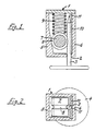
- the fastening clip shown in the drawing comprises a housing 1 having an opening 2 through which a shank 3 of a pin member 4 to be secured to the housing, is inserted.
- the housing 1 comprises opposed side walls 5 and 6, and the interior of the side wall 5 converges towards the side wall 6 in the direction towards the opening 2.
- a wedging member formed as a roller 7 is placed with the axis thereof lying parallel to the walls 5 and 6.
- the roller Opposite the opening 2, the roller comprises a circumferential guide groove 8 extending in a radial plane, and the roller is so dimensioned that on insertion of a shank 3 against the bias of a pressure spring 9 it will be pressed in a direction away from the opening 2 in such a manner that when the shank 3 is subsequently pulled outwards, the roller will function as a wedging member pressing the shank against the wall 6 and preventing by friction that the pin member 4 is withdrawn from the housing 1.
- the roller 7 is preferably made of hardened steel, and the guide groove 8 has sharp edges where joining the cylindrical surface of the roller.
- the sharp edges and the hard material permit the roller during the wedging to catch a firm hold in the shank 3 which consists of a softer material.
- the housing 1 may also be made of a relatively hard material, but usually it consists of a cheap material, e.g. of plastic, and in this case it is preferred to place at the inner side of the wall 6 a hard metal plate 10 absorbing the wedging pressure from the roller 7. Furthermore, it has proved to be expedient to provide a guiding for the shank 3 in the shape of a groove 11 in the wall 6 or in the metal plate 10 which ensures that the shank 3 will not tilt but will always remain in a position where the sharp edges of the guide groove 8 of the roller are permitted to penetrate into the shank and stamp it. Considering the diameter and the material of the shank, the optimum width of the guide groove 8 for the best possible stamping and retaining of the shank by a kind of three-point fixing is easily determined in practice.
- the fastening clip is especially intended for attaching to articles of clothing or similar flat articles, an identification tag or a plate which is adapted to release an acoustic burglar alarm at the exit from a shop, and the housing of the fastening clip is preferably formed on a plate which is connected along its periphery with a plate of a similar contour, closing the end of the housing remote from the opening and forming with the first mentioned plate a capsule containing a coil adapted to activate a burglar alarm at the exit from the shop.
- the shop assistant places the housing 1 of the fastening clip in such correct position relative to the magnetic field of a specially formed magnet that the roller 7 is moved against the bias of the spring 9 in a direction away from the opening 2 so that the shank 3 is no longer wedged but is permitted to be withdrawn from the housing.
Landscapes
- Clamps And Clips (AREA)
- Burglar Alarm Systems (AREA)
Applications Claiming Priority (2)
| Application Number | Priority Date | Filing Date | Title |
|---|---|---|---|
| DK478782A DK148370C (da) | 1982-10-28 | 1982-10-28 | Laaseklemme |
| DK4787/82 | 1982-10-28 |
Publications (2)
| Publication Number | Publication Date |
|---|---|
| EP0124564A1 EP0124564A1 (en) | 1984-11-14 |
| EP0124564B1 true EP0124564B1 (en) | 1986-07-16 |
Family
ID=8136660
Family Applications (1)
| Application Number | Title | Priority Date | Filing Date |
|---|---|---|---|
| EP83903531A Expired EP0124564B1 (en) | 1982-10-28 | 1983-10-27 | Fastening clip |
Country Status (6)
| Country | Link |
|---|---|
| EP (1) | EP0124564B1 (it) |
| JP (1) | JPS60500782A (it) |
| DE (1) | DE3364535D1 (it) |
| DK (1) | DK148370C (it) |
| IT (1) | IT1170547B (it) |
| WO (1) | WO1984001847A1 (it) |
Families Citing this family (10)
| Publication number | Priority date | Publication date | Assignee | Title |
|---|---|---|---|---|
| US4670950A (en) * | 1985-05-13 | 1987-06-09 | Monarch Marking Systems, Inc. | Theft-deterrent tag |
| DK155388C (da) * | 1986-07-08 | 1989-10-23 | Palle Pedersen | Laas |
| DE3704051A1 (de) * | 1987-02-10 | 1988-08-18 | Veith Gmbh Co Gustav Georg | Klemme |
| NL9102005A (nl) * | 1991-11-29 | 1993-06-16 | Dutch A & A Trading Bv | Diefstalbeveiligingslabel. |
| GB2297793A (en) * | 1995-02-10 | 1996-08-14 | Ronald Edward Hurman | Rolling element locking system |
| AU5210799A (en) | 1998-07-10 | 2000-02-01 | Tydenbrammall, Inc. | Cable lock with security insert |
| JP4425479B2 (ja) * | 2000-02-17 | 2010-03-03 | 三井化学株式会社 | ポリ1−ブテン樹脂組成物およびその組成物からなるパイプ |
| RU2211904C1 (ru) * | 2002-07-02 | 2003-09-10 | Закрытое акционерное общество "Инженерный Промышленный Концерн "Страж" | Одноразовое запорно-пломбировочное устройство |
| WO2015118441A1 (en) * | 2014-02-07 | 2015-08-13 | Mgt Industries S.R.L. | Quick connection and/or fastening system |
| CN107098060A (zh) * | 2017-05-25 | 2017-08-29 | 武汉纺织大学 | 一种采集盛装专用容器及其使用方法 |
Family Cites Families (5)
| Publication number | Priority date | Publication date | Assignee | Title |
|---|---|---|---|---|
| US3858280A (en) * | 1972-11-17 | 1975-01-07 | I D Engineering Inc | Fastening clip |
| US3911534A (en) * | 1974-10-30 | 1975-10-14 | I D Engineering Inc | Anti-theft fastening device |
| US3974581A (en) * | 1974-10-30 | 1976-08-17 | I. D. Engineering, Inc. | Anti-theft fastening device and tool for releasing same |
| DK141674B (da) * | 1977-04-05 | 1980-05-19 | Brammall Inc | Kabellås. |
| US4299870A (en) * | 1980-05-27 | 1981-11-10 | Sensormatic Electronics Corporation | Reusable theft deterrent security tag |
-
1982
- 1982-10-28 DK DK478782A patent/DK148370C/da not_active IP Right Cessation
-
1983
- 1983-10-27 IT IT49232/83A patent/IT1170547B/it active
- 1983-10-27 EP EP83903531A patent/EP0124564B1/en not_active Expired
- 1983-10-27 JP JP58503538A patent/JPS60500782A/ja active Pending
- 1983-10-27 WO PCT/DK1983/000100 patent/WO1984001847A1/en not_active Ceased
- 1983-10-27 DE DE8383903531T patent/DE3364535D1/de not_active Expired
Also Published As
| Publication number | Publication date |
|---|---|
| IT8349232A1 (it) | 1985-04-27 |
| IT1170547B (it) | 1987-06-03 |
| DK148370C (da) | 1986-02-10 |
| JPS60500782A (ja) | 1985-05-23 |
| DK478782A (da) | 1984-04-29 |
| DK148370B (da) | 1985-06-17 |
| DE3364535D1 (en) | 1986-08-21 |
| WO1984001847A1 (en) | 1984-05-10 |
| EP0124564A1 (en) | 1984-11-14 |
| IT8349232A0 (it) | 1983-10-27 |
Similar Documents
| Publication | Publication Date | Title |
|---|---|---|
| US4685234A (en) | Surveillance marker clip assembly | |
| US3858280A (en) | Fastening clip | |
| US6449991B1 (en) | One part theft deterrent device | |
| EP0463727B1 (en) | Pin-clutch mechanism for theft deterrent device | |
| US4903383A (en) | Anti-theft fastening | |
| US3974581A (en) | Anti-theft fastening device and tool for releasing same | |
| US3947930A (en) | Anti-theft fastening device and tool for releasing same | |
| US6052876A (en) | Versatile attachment mechanism for theft deterrent tags | |
| AU677382B2 (en) | Anti-theft device for bottles | |
| US4523356A (en) | Ball clutch mechanism with two sets of balls in separate radial planes | |
| US5079540A (en) | Theft detection tag with adjustable loop | |
| WO1984001847A1 (en) | Fastening clip | |
| CN101107412B (zh) | 具有可拆卸圆头钉钮扣状物的识别/监视装置 | |
| US5611583A (en) | Cable lock and seal with coiled spring | |
| EP0483986A1 (en) | Release of pin-clutch mechanism in theft-deterrent device | |
| US4280256A (en) | Fastener apparatus | |
| JP2003102122A (ja) | 定着した係止装置を備える低挿入力ケーブルタイ | |
| IL163010A (en) | Hard security tag and disconnect device | |
| US8117874B2 (en) | Theft deterrent device including a spring washer | |
| AU9370398A (en) | An anti-theft device with a thermally controllable locking mechanism | |
| US20180197391A1 (en) | Security Tag | |
| US3971269A (en) | Fastening clip and tool for releasing same | |
| US4779911A (en) | Padlock seal | |
| EP0404265A1 (en) | Friction lock | |
| GB2611581A (en) | Security tag |
Legal Events
| Date | Code | Title | Description |
|---|---|---|---|
| PUAI | Public reference made under article 153(3) epc to a published international application that has entered the european phase |
Free format text: ORIGINAL CODE: 0009012 |
|
| AK | Designated contracting states |
Designated state(s): BE CH DE FR GB LI NL SE |
|
| 17P | Request for examination filed |
Effective date: 19841003 |
|
| GRAA | (expected) grant |
Free format text: ORIGINAL CODE: 0009210 |
|
| AK | Designated contracting states |
Kind code of ref document: B1 Designated state(s): BE CH DE FR GB LI NL SE |
|
| REF | Corresponds to: |
Ref document number: 3364535 Country of ref document: DE Date of ref document: 19860821 |
|
| ET | Fr: translation filed | ||
| PGFP | Annual fee paid to national office [announced via postgrant information from national office to epo] |
Ref country code: NL Payment date: 19861031 Year of fee payment: 4 |
|
| PLBE | No opposition filed within time limit |
Free format text: ORIGINAL CODE: 0009261 |
|
| STAA | Information on the status of an ep patent application or granted ep patent |
Free format text: STATUS: NO OPPOSITION FILED WITHIN TIME LIMIT |
|
| 26N | No opposition filed | ||
| PG25 | Lapsed in a contracting state [announced via postgrant information from national office to epo] |
Ref country code: SE Effective date: 19871028 |
|
| PG25 | Lapsed in a contracting state [announced via postgrant information from national office to epo] |
Ref country code: LI Effective date: 19871031 Ref country code: CH Effective date: 19871031 Ref country code: BE Effective date: 19871031 |
|
| BERE | Be: lapsed |
Owner name: MICROSCAN LTD. Effective date: 19871031 |
|
| PG25 | Lapsed in a contracting state [announced via postgrant information from national office to epo] |
Ref country code: NL Effective date: 19880501 |
|
| NLV4 | Nl: lapsed or anulled due to non-payment of the annual fee | ||
| GBPC | Gb: european patent ceased through non-payment of renewal fee | ||
| PG25 | Lapsed in a contracting state [announced via postgrant information from national office to epo] |
Ref country code: FR Free format text: LAPSE BECAUSE OF NON-PAYMENT OF DUE FEES Effective date: 19880630 |
|
| REG | Reference to a national code |
Ref country code: CH Ref legal event code: PL |
|
| PG25 | Lapsed in a contracting state [announced via postgrant information from national office to epo] |
Ref country code: DE Effective date: 19880701 |
|
| REG | Reference to a national code |
Ref country code: FR Ref legal event code: ST |
|
| PG25 | Lapsed in a contracting state [announced via postgrant information from national office to epo] |
Ref country code: GB Effective date: 19881122 |
|
| EUG | Se: european patent has lapsed |
Ref document number: 83903531.8 Effective date: 19880712 |