EP0124785A2 - Manche pour tir de bataille - Google Patents
Manche pour tir de bataille Download PDFInfo
- Publication number
- EP0124785A2 EP0124785A2 EP84103871A EP84103871A EP0124785A2 EP 0124785 A2 EP0124785 A2 EP 0124785A2 EP 84103871 A EP84103871 A EP 84103871A EP 84103871 A EP84103871 A EP 84103871A EP 0124785 A2 EP0124785 A2 EP 0124785A2
- Authority
- EP
- European Patent Office
- Prior art keywords
- metallic components
- fabric
- drag
- repeat
- hollow body
- Prior art date
- Legal status (The legal status is an assumption and is not a legal conclusion. Google has not performed a legal analysis and makes no representation as to the accuracy of the status listed.)
- Granted
Links
Images


Classifications
-
- F—MECHANICAL ENGINEERING; LIGHTING; HEATING; WEAPONS; BLASTING
- F41—WEAPONS
- F41J—TARGETS; TARGET RANGES; BULLET CATCHERS
- F41J2/00—Reflecting targets, e.g. radar-reflector targets; Active targets transmitting electromagnetic or acoustic waves
-
- F—MECHANICAL ENGINEERING; LIGHTING; HEATING; WEAPONS; BLASTING
- F41—WEAPONS
- F41J—TARGETS; TARGET RANGES; BULLET CATCHERS
- F41J9/00—Moving targets, i.e. moving when fired at
- F41J9/08—Airborne targets, e.g. drones, kites, balloons
- F41J9/10—Airborne targets, e.g. drones, kites, balloons towed
Definitions
- the invention relates to a battle target air drag bag with a device for radar detection, consisting of a hollow body made of annularly reinforced textile fabric webs, into which elongated metallic components are incorporated, and a front drag gear and a floor.
- a battle target air drag bag of this type is known from DE-O S 26 02 432.
- the elongated metallic components are arranged on the hollow body at intervals of less than or equal to a quarter of the wavelength of the radar frequency used.
- Metal threads are used in particular as elongated metallic components, individual textile threads of the textile fabric being twisted or wrapped with a metal thread and running in the warp or weft direction or also in both directions.
- the prior art also includes a radar-sensitive target cloth (DE-GM 17 91 564), which contains metallic wires or yarns in warp and / or weft.
- the base fabric of the target cloth consists of monofilament polyethylene wires, into which three bronze wires consisting of several individual wires are shot alternately with three polyethylene wires.
- a corresponding object results from US-PS 27 31 046, according to which individual filaments made of polyethylene have a wrapping or coating made of metal, for example aluminum.
- at least individual fabric threads are designed in a contrasting color in order to emphasize them visually.
- the beams then hit not on a transverse surface to them, but in the extreme case only on the thin front edge of the T extilgewebebahnen the respective tow target, and this is connected to the known means no usable reflection.
- the invention is based on the object with regard also to improve a combat target aerial tow the initially given genus its detectability by radio beams during the arrival and on departure and to make him unchanged erbrauchsneuvestand with minimum effort as V produced.
- the invention has the advantage that the drag sack is reflective in the same way both during approach and departure and is efficient regardless of the drag sack length on the one hand and the technical requirements in the manufacture of the textile fabric in question, in particular with regard to the repeat, on the other hand can produce larger quantities. In particular, making the cuts for the paths of the hollow body can be made with very little effort due to the invention.
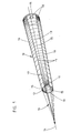
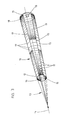
- the battle target air drag bag consists according to FIGS. 1 and 3 in each case of a very elongated, frustoconical hollow body 10 with a closed bottom 11 and at the front end 12 attacking, referred to as "spider" towing gear 13, to which a tow line 14 of the towing aircraft, not shown, is attached.
- the hollow body 10 is composed of a plurality of longitudinal textile fabric webs 15, 16, for example according to FIGS. 1 and 3, of six fabric webs which are sewn together on their longitudinal edges. Surrender Six panel seams 17, and according to this N ähtebaum also the towing gear 13 has six cords. Near the drag bag bottom 11 has each web 1 5, 16 is a Vietnamese gutströmö réelle 18th The material of the base 11 is more permeable to air than that of the webs 15, 16, which should not let air through, and therefore still have a coating of, for example, acrylic resin on the inside of the hollow body.
- the textile fabric of the webs 15, 16 consists of a conventionally woven fabric with warp and weft threads.
- This can be textile threads made from fiber yarns, e.g. B. made of acrylonitrile fibers.
- the goods shown in FIGS. 2 and 4 are, for example, 1.40 m wide.
- Elongated metallic components are also provided for part of the weft threads, namely metal threads 19 of so-called lame quality in the exemplary embodiments described.
- the distances between the injected metal threads 19 are not the same, but rather increase from a comparatively small minimum distance, e.g. B. 1 mm, based on a mathematical law up to a comparatively large maximum distance, z. B. 150 mm, which is illustrated in the drawing by a corresponding staggered hatching.
- a complete rhythm of injected metal threads 19 between the outermost thread at the minimum distance on the one hand and the outermost thread at the maximum distance on the other hand forms a repeat 20 on the textile fabric according to FIGS. 2 and 4, the side of the minimum distance of the metal threads 19 - in the Figures left - another seam allowance 21 is added so that the repeat 20 includes the seam allowance.
- the hem allowance 21 according to FIG. 2 is free of metallic weft threads, so that there is an empty area between the respective repeat end with the maximum distance of the metal threads 19 and the next start of the weft rhythm with the minimum distance.
- a hem allowance 21 is also provided, but this also contains metallic weft threads 19, that is to say they continue in rhythm with the hem allowance.
- the next repeat begins again with a corresponding seam allowance etc. etc.
- the cut length 22 (usable length) extends from the center to the center of the successive seam allowances 21
- a corresponding fabric strip is available for the edging of the annular reinforcement (not shown in the drawing) at the front end 12 of the hollow body 10 and for the sewing of the base 11.
- the repeat 2D is the same as the cut length 22 and is approximately 3.80 m long.
- the fabric sheets 15, 16 of the hollow body 10 are cut out from a repeat 20 in oppositely arranged trapezoids, as is indicated in FIGS. 2 and 4 by the dash-dotted lines 23.
- the cutting lines 23 readily create the Fabric webs 15, the minimum distance between the metallic weft threads 19 is at the front of the drag sack, and the fabric webs 16, the minimum distance between the metal threads 19 is located at the rear of the drag sack. This has the associated effect that the towing target can be located and measured even during arrival and departure, for example, 10 km away.
- the longitudinal seams 17 inevitably fit to one another, so that difficulties in manufacture, for example wrinkling, cannot occur.
- the exemplary embodiment shown in FIG. 4, in which seam allowances that are free of metallic weft threads have been dispensed with, has the advantage that the metallic weft threads 19 do not need to be interrupted, rather the outermost metal thread 19 at the end can be at the maximum distance connect a rhythm directly to the outermost metal thread at the minimum distance.
- any sections of the fabric web according to FIG. 4 are simply provided and cut, it being irrelevant what distance the metallic weft threads 19 have at this point.
- Such a towing target is shown in FIG. 3.
- the rhythm of the metal threads 19 does not begin here only at one end of the hollow body 10, but also in the central region of the relevant fabric web 15, 16 with the minimum distance new and extends as far in the direction of the maximum distance as it corresponds to the construction length of the hollow body 10.
- the respective tracks 15 and the respective tracks 16 can have different configurations with regard to the respective course from the minimum distance to the maximum distance of the weft threads 19. In this way, a wide field of possibilities opens up for the execution of the hollow body 10 with the webs 15, 16 without the desired effect being impaired if only the rhythm of the metal threads 19 injected per web alternately once in this and then in that direction runs. This results in considerable savings in terms of production.
Landscapes
- Engineering & Computer Science (AREA)
- General Engineering & Computer Science (AREA)
- Aviation & Aerospace Engineering (AREA)
- Physics & Mathematics (AREA)
- Electromagnetism (AREA)
- Radar, Positioning & Navigation (AREA)
- Remote Sensing (AREA)
- Woven Fabrics (AREA)
Applications Claiming Priority (2)
| Application Number | Priority Date | Filing Date | Title |
|---|---|---|---|
| DE19833312820 DE3312820A1 (de) | 1983-04-09 | 1983-04-09 | Gefechtsziel-luftschleppsack |
| DE3312820 | 1983-04-09 |
Publications (3)
| Publication Number | Publication Date |
|---|---|
| EP0124785A2 true EP0124785A2 (fr) | 1984-11-14 |
| EP0124785A3 EP0124785A3 (en) | 1988-10-12 |
| EP0124785B1 EP0124785B1 (fr) | 1991-01-23 |
Family
ID=6195867
Family Applications (1)
| Application Number | Title | Priority Date | Filing Date |
|---|---|---|---|
| EP84103871A Expired - Lifetime EP0124785B1 (fr) | 1983-04-09 | 1984-04-07 | Manche pour tir de bataille |
Country Status (6)
| Country | Link |
|---|---|
| US (1) | US4540987A (fr) |
| EP (1) | EP0124785B1 (fr) |
| AU (1) | AU562502B2 (fr) |
| CA (1) | CA1235716A (fr) |
| DE (1) | DE3312820A1 (fr) |
| ZA (1) | ZA842608B (fr) |
Cited By (3)
| Publication number | Priority date | Publication date | Assignee | Title |
|---|---|---|---|---|
| US5026073A (en) * | 1989-04-26 | 1991-06-25 | Teledyne Industries, Inc. | Aerial gunnery target |
| US5078406A (en) * | 1989-04-26 | 1992-01-07 | Teledyne Industries, Inc. | Aerial gunnery target |
| EP0543170A1 (fr) * | 1991-11-19 | 1993-05-26 | Ingenieurbüro für Elektro-Mechanische Technologien Dipl.-Ing. Hartmut Euer | Cible aérienne remorquée pour haute vitesse, en matériel textile, avec trainée de remorque réduite |
Families Citing this family (5)
| Publication number | Priority date | Publication date | Assignee | Title |
|---|---|---|---|---|
| DE3436063A1 (de) * | 1984-10-02 | 1986-04-10 | Autoflug Gmbh, 2084 Rellingen | Gestaffelte anordnung zur verbesserung der radarreflexion |
| US4709235A (en) * | 1986-11-14 | 1987-11-24 | Loral Corporation | Low-drag, ram-air inflated, millimeter wave, passive radar decoy |
| EP0435694B1 (fr) * | 1989-12-29 | 1995-08-09 | Canon Kabushiki Kaisha | Imprimante et machine à écrire électronique |
| US5028928A (en) * | 1990-06-26 | 1991-07-02 | Vidmar Robert J | Ultra-stable, stressed-skin inflatable target support systems |
| GB9114052D0 (en) * | 1991-06-28 | 1991-08-14 | Tti Tactical Technologies Inc | Towed multi-band decoy |
Family Cites Families (14)
| Publication number | Priority date | Publication date | Assignee | Title |
|---|---|---|---|---|
| US1860982A (en) * | 1931-03-27 | 1932-05-31 | John A Binnie | Aerial device |
| US2412562A (en) * | 1943-05-21 | 1946-12-17 | British Celanese | Fabric |
| US2402156A (en) * | 1944-05-27 | 1946-06-18 | John W Griesinger | Astern attack tow target |
| US2419549A (en) * | 1944-08-24 | 1947-04-29 | John W Griesinger | Radio reflecting and low drag tow target |
| US2731046A (en) * | 1951-10-01 | 1956-01-17 | Firestone Tire & Rubber Co | Tow target |
| US2907095A (en) * | 1956-07-31 | 1959-10-06 | Massillon Cleveland Akron Sign Co | Tow target construction |
| DE1791564U (de) * | 1959-03-20 | 1959-07-02 | Ver Seidenwebereien A G | Radarempfindliches zieltuch. |
| US3354458A (en) * | 1966-05-20 | 1967-11-21 | Goodyear Aerospace Corp | Wire-film space satellite |
| DE2602432A1 (de) * | 1976-01-23 | 1977-07-28 | Autoflug Gmbh | Gefechtsziel-luftschleppsack |
| DE2604929A1 (de) * | 1976-02-09 | 1977-08-11 | Gfh Ges Fuer Flugtechnik Mbh | Luftzielschleppsack, der als schleppkoerper hinter einem luftfahrzeug zur simulation eines flugkoerpers fuer radargelenkte oder radargestuetzte luftabwehrwaffen gezogen wird |
| US4184681A (en) * | 1977-08-29 | 1980-01-22 | Goodyear Aerospace Corporation | Ram-air inflatable, fabric, towed gunnery target |
| US4205848A (en) * | 1978-04-10 | 1980-06-03 | Prototype Development Associates, Inc. | Aerial gunnery target |
| US4195798A (en) * | 1978-09-15 | 1980-04-01 | The United States Of America As Represented By The Secretary Of The Navy | Universal tow target adapter |
| DE3015926A1 (de) * | 1980-04-25 | 1981-10-29 | Elektro-Mechanischer Fluggerätebau GmbH, 2000 Hamburg | Schleppkoerperanordnung |
-
1983
- 1983-04-09 DE DE19833312820 patent/DE3312820A1/de not_active Ceased
-
1984
- 1984-04-06 US US06/597,435 patent/US4540987A/en not_active Expired - Fee Related
- 1984-04-06 CA CA000451487A patent/CA1235716A/fr not_active Expired
- 1984-04-07 EP EP84103871A patent/EP0124785B1/fr not_active Expired - Lifetime
- 1984-04-09 AU AU26643/84A patent/AU562502B2/en not_active Ceased
- 1984-04-09 ZA ZA842608A patent/ZA842608B/xx unknown
Cited By (4)
| Publication number | Priority date | Publication date | Assignee | Title |
|---|---|---|---|---|
| US5026073A (en) * | 1989-04-26 | 1991-06-25 | Teledyne Industries, Inc. | Aerial gunnery target |
| US5078406A (en) * | 1989-04-26 | 1992-01-07 | Teledyne Industries, Inc. | Aerial gunnery target |
| EP0543170A1 (fr) * | 1991-11-19 | 1993-05-26 | Ingenieurbüro für Elektro-Mechanische Technologien Dipl.-Ing. Hartmut Euer | Cible aérienne remorquée pour haute vitesse, en matériel textile, avec trainée de remorque réduite |
| US5338199A (en) * | 1991-11-19 | 1994-08-16 | Ingenieurburo Fur Elektro-Mechanische Technologien Dipl-Ing Hartmut Euer | Aerial tow target |
Also Published As
| Publication number | Publication date |
|---|---|
| AU2664384A (en) | 1984-10-11 |
| EP0124785B1 (fr) | 1991-01-23 |
| CA1235716A (fr) | 1988-04-26 |
| ZA842608B (en) | 1984-11-28 |
| DE3312820A1 (de) | 1984-10-18 |
| EP0124785A3 (en) | 1988-10-12 |
| AU562502B2 (en) | 1987-06-11 |
| US4540987A (en) | 1985-09-10 |
Similar Documents
| Publication | Publication Date | Title |
|---|---|---|
| DE4107633C2 (de) | Doppelgewebe für eine Papiermaschine | |
| DE1927994C3 (de) | Befestigungsanordnung für einen einklappbar an einem Meßbandende angeordneten Haken | |
| EP0124785B1 (fr) | Manche pour tir de bataille | |
| DE3713813C2 (fr) | ||
| DE3928485C2 (de) | Papiermaschinentuch | |
| DE2114006C3 (de) | Verstärkungseinlage für Bänder oder Riemen, insbesondere Förderbänder | |
| DE3028918A1 (de) | Gewebtes reissverschlussband | |
| DE2602432A1 (de) | Gefechtsziel-luftschleppsack | |
| DE3513325A1 (de) | Haftverschluss | |
| DE2739431A1 (de) | Luftlenkender kamm fuer einen duesenwebstuhl | |
| DE69007581T2 (de) | Luftziel zum beschuss mit kanonen. | |
| DE3137304C2 (de) | Gleitfallschirm | |
| DE3041162A1 (de) | Gewebtes reissberschlusstragband | |
| DE3104094A1 (de) | "strahlduese mit abgeschirmt vorgesehener spritzoeffnung, geeignet fuer eine schuetzenlose webmaschine" | |
| DE3338697A1 (de) | Lenkgeschoss | |
| EP0786547A1 (fr) | Procédé et dispositif de rentrage d'un fil de trame | |
| DE674433C (de) | An Luftfahrzeugen angeordnete, aus Wellblech bestehende Aussenbeplankung | |
| DE102018102647B4 (de) | Schutzplane, insbesondere für einen LKW-Aufbau oder für einen Zelt-Aufbau oder für ein Tor | |
| DE1779693C3 (de) | Trag und Kräuselband für Vor hange oder Gardinen mit Taschen für Traghaken oder dgl | |
| EP0058227B1 (fr) | Rameuse pour bandes textiles | |
| DE19528174C2 (de) | Gleitschirm in V-Rippenbauweise mit V-Naht | |
| DE3034120A1 (de) | Eintragskanal fuer eine duesenwebmaschine | |
| DE2548028C3 (de) | Verfahren zur Herstellung von kugelförmigen bzw. halbkugelförmigen Troddeln | |
| DE104819C (fr) | ||
| DE858825C (de) | Mit einer Gewebebahn versehener Treibriemen, Foerderband od. dgl. |
Legal Events
| Date | Code | Title | Description |
|---|---|---|---|
| PUAI | Public reference made under article 153(3) epc to a published international application that has entered the european phase |
Free format text: ORIGINAL CODE: 0009012 |
|
| AK | Designated contracting states |
Designated state(s): BE CH FR GB IT LI NL SE |
|
| PUAL | Search report despatched |
Free format text: ORIGINAL CODE: 0009013 |
|
| AK | Designated contracting states |
Kind code of ref document: A3 Designated state(s): BE CH FR GB IT LI NL SE |
|
| 17P | Request for examination filed |
Effective date: 19890107 |
|
| 17Q | First examination report despatched |
Effective date: 19890907 |
|
| GRAA | (expected) grant |
Free format text: ORIGINAL CODE: 0009210 |
|
| AK | Designated contracting states |
Kind code of ref document: B1 Designated state(s): BE CH FR GB IT LI NL SE |
|
| PG25 | Lapsed in a contracting state [announced via postgrant information from national office to epo] |
Ref country code: SE Effective date: 19910408 |
|
| ET | Fr: translation filed | ||
| ITF | It: translation for a ep patent filed | ||
| PG25 | Lapsed in a contracting state [announced via postgrant information from national office to epo] |
Ref country code: BE Effective date: 19910430 Ref country code: CH Effective date: 19910430 Ref country code: LI Effective date: 19910430 |
|
| GBT | Gb: translation of ep patent filed (gb section 77(6)(a)/1977) | ||
| BERE | Be: lapsed |
Owner name: AUTOFLUG G.M.B.H. Effective date: 19910430 |
|
| PLBE | No opposition filed within time limit |
Free format text: ORIGINAL CODE: 0009261 |
|
| STAA | Information on the status of an ep patent application or granted ep patent |
Free format text: STATUS: NO OPPOSITION FILED WITHIN TIME LIMIT |
|
| REG | Reference to a national code |
Ref country code: CH Ref legal event code: PL |
|
| 26N | No opposition filed | ||
| PGFP | Annual fee paid to national office [announced via postgrant information from national office to epo] |
Ref country code: NL Payment date: 19930430 Year of fee payment: 10 |
|
| PGFP | Annual fee paid to national office [announced via postgrant information from national office to epo] |
Ref country code: FR Payment date: 19930624 Year of fee payment: 10 |
|
| PGFP | Annual fee paid to national office [announced via postgrant information from national office to epo] |
Ref country code: GB Payment date: 19930701 Year of fee payment: 10 |
|
| PG25 | Lapsed in a contracting state [announced via postgrant information from national office to epo] |
Ref country code: GB Effective date: 19940407 |
|
| PG25 | Lapsed in a contracting state [announced via postgrant information from national office to epo] |
Ref country code: NL Effective date: 19941101 |
|
| GBPC | Gb: european patent ceased through non-payment of renewal fee |
Effective date: 19940407 |
|
| NLV4 | Nl: lapsed or anulled due to non-payment of the annual fee | ||
| PG25 | Lapsed in a contracting state [announced via postgrant information from national office to epo] |
Ref country code: FR Effective date: 19941229 |
|
| EUG | Se: european patent has lapsed |
Ref document number: 84103871.4 Effective date: 19911108 |
|
| REG | Reference to a national code |
Ref country code: FR Ref legal event code: ST |