EP0124886B1 - Revêtement pour un mur ou un plafond - Google Patents
Revêtement pour un mur ou un plafond Download PDFInfo
- Publication number
- EP0124886B1 EP0124886B1 EP84105004A EP84105004A EP0124886B1 EP 0124886 B1 EP0124886 B1 EP 0124886B1 EP 84105004 A EP84105004 A EP 84105004A EP 84105004 A EP84105004 A EP 84105004A EP 0124886 B1 EP0124886 B1 EP 0124886B1
- Authority
- EP
- European Patent Office
- Prior art keywords
- sections
- wall
- shuttering
- claws
- specified
- Prior art date
- Legal status (The legal status is an assumption and is not a legal conclusion. Google has not performed a legal analysis and makes no representation as to the accuracy of the status listed.)
- Expired - Lifetime
Links
- 210000000078 claw Anatomy 0.000 claims description 21
- 239000002184 metal Substances 0.000 claims description 16
- 125000006850 spacer group Chemical group 0.000 claims description 9
- 239000000463 material Substances 0.000 claims description 2
- 238000009416 shuttering Methods 0.000 claims 6
- 241000282979 Alces alces Species 0.000 claims 1
- 230000006835 compression Effects 0.000 claims 1
- 238000007906 compression Methods 0.000 claims 1
- 238000009415 formwork Methods 0.000 description 7
- 239000002023 wood Substances 0.000 description 6
- 238000009413 insulation Methods 0.000 description 3
- 210000001364 upper extremity Anatomy 0.000 description 3
- 230000009286 beneficial effect Effects 0.000 description 1
- 238000005253 cladding Methods 0.000 description 1
- 238000007796 conventional method Methods 0.000 description 1
- 230000000694 effects Effects 0.000 description 1
- 230000002787 reinforcement Effects 0.000 description 1
- 239000012858 resilient material Substances 0.000 description 1
Images

Classifications
-
- E—FIXED CONSTRUCTIONS
- E04—BUILDING
- E04F—FINISHING WORK ON BUILDINGS, e.g. STAIRS, FLOORS
- E04F13/00—Coverings or linings, e.g. for walls or ceilings
- E04F13/07—Coverings or linings, e.g. for walls or ceilings composed of covering or lining elements; Sub-structures therefor; Fastening means therefor
- E04F13/08—Coverings or linings, e.g. for walls or ceilings composed of covering or lining elements; Sub-structures therefor; Fastening means therefor composed of a plurality of similar covering or lining elements
- E04F13/0801—Separate fastening elements
- E04F13/0803—Separate fastening elements with load-supporting elongated furring elements between wall and covering elements
- E04F13/081—Separate fastening elements with load-supporting elongated furring elements between wall and covering elements with additional fastening elements between furring elements and covering elements
- E04F13/0821—Separate fastening elements with load-supporting elongated furring elements between wall and covering elements with additional fastening elements between furring elements and covering elements the additional fastening elements located in-between two adjacent covering elements
- E04F13/0826—Separate fastening elements with load-supporting elongated furring elements between wall and covering elements with additional fastening elements between furring elements and covering elements the additional fastening elements located in-between two adjacent covering elements engaging side grooves running along the whole length of the covering elements
Definitions
- the invention relates to facing formwork for a wall or ceiling made of slotted plates on its long sides, in particular wood or wood-based panels, which are mounted by means of claws in the grooves on profiles which are attached to the wall or ceiling.
- the conventional method of fastening a wall or ceiling formwork is to attach a substructure made of wooden slats to the wall or ceiling and nail the formwork panels to it.
- the irregularities of the wall or the like are interposed by interposing wedges. balanced under the substructure at their fastening points.
- a substructure made of metal profiles has been developed with claws that engage in the grooves of the plates (DE-PS 1 292 355).
- the metal profiles are held on a wall, for example, by means of set screws screwed into the wall, on which they are clamped between two nuts; Adjustable hangers are often used on a ceiling.
- the claws are clipped onto the metal profiles wherever they are needed, and are moved a little bit while overcoming their clamping on the metal profiles and brought into engagement with the grooves.
- Another proposal to simplify assembly is to connect the plates by means of springs that engage in their grooves and to fasten them directly to the wall without the need for a substructure by means of anchors that consist of screws that reach through the springs into wall dowels as tension elements and against the wall as well as resilient spacers supported against the springs as flexible elements opposing and interacting with the tension elements (DE-OS 28 44 920).
- anchors consist of screws that reach through the springs into wall dowels as tension elements and against the wall as well as resilient spacers supported against the springs as flexible elements opposing and interacting with the tension elements (DE-OS 28 44 920).
- the required distance from the wall can be easily adjusted with the amount of screwing in, whereby it is also possible to unscrew the screw a bit, and screw it back and forth as required until the correct setting is found, since the elastic spacers are always there to adjust. At the same time, there is good thermal and acoustic insulation.
- the invention has for its object to further simplify the assembly of facing formwork. The possibility of heat and soundproofing designs should remain.
- the invention takes up the facing formwork of the genus described in the introduction and provides that the profiles are fastened to the wall or ceiling by means of the known anchors known per se, which are made of screws which extend through the profiles into dowels placed in the wall or ceiling as tension elements and against the wall or ceiling and against the profiles supported, elastic spacers as the tensile elements opposing and interacting with them resilient pressure elements.
- the proposal to fasten the profiles by means of the known anchors is based on the knowledge and takes advantage of the fact that the direct fastening of the plates by means of the claws, in contrast to nailing, for example, only stresses the substructure in a way that is beneficial to them allows elastic support against the wall.
- the effects of heat and sound insulation explained in DE-AS 28 44 920 apply essentially here, both, but mainly sound insulation, by a felt or the like. Covering on the contact surface of the profiles for the plates can be improved.
- the spacers can turn the coil springs or sleeves surrounding the screws made of resilient material.
- the profiles fastened according to the invention are particularly suitable as a basis for the further configuration which simplifies assembly, in order to slide the claws on them. Similar to curtain rolls, the sliding claws are inserted or pushed in at the required number at the end of the profile and pushed in whole or in part near the respective assembly point and then used or pushed as needed.
- the handling can be fully concentrated on them. There is no longer any need to grab claws from a supply in between, bring them in, lay them flat against the profile and clip them on by twisting.
- the sliding claws are practically already in place. Tool changes are also not required. The workload is significantly reduced.
- the fastening of the profiles according to the invention leads to certain distortions of the profiles, especially in the particularly expedient case of the direct cladding of a shell wall.
- the twisted profiles can be bent easily when installing a wood or wood-based panel. Everywhere there are slight jams and elastic adjustments, which in the end result make the formwork free of play despite the play required for the sliding guidance.
- the profiles are preferably U-profiles with legs bent inwards at their ends. If they are made of plastic, the inwardly bent legs are expediently connected to the back of the profile for reinforcement by webs.
- the claws are stamped sheet metal parts which are arranged with the original sheet metal plane in the profile and abut from behind on the bent ends of the legs of the profile and which are angled out in a hook shape between the end edges of these bent ends from the original sheet metal plane and overlap the bent ends of the metal profile with a widening of their hook-shaped part.
- a shell wall On a shell wall 1, e.g. four profiles 2 made of metal, one near the floor, one near the ceiling and two at regular intervals, e.g. fastened every 70 to 80 cm by means of a screw 3 which is passed through the profile 2 and e.g. from a piece of hose existing elastic spacer 4 engages in a wall dowel not shown in the drawing.
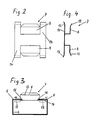
- the profiles 2 are box profiles with a cutout 5 on their front. Behind the front legs 6 of the profiles 2 that remain on both sides of the cutout 5, claws 7 are held, which engage with grooves 8, each protruding through the cutout 5, into grooves 10 milled into the narrow sides of wooden panels 9.
- the claws are made as sheet metal stamped parts with four incisions 11, a flap being formed between two incisions and hook-shaped bent out to the front at the mentioned angle 8.
- the ends 12 of the angle 8 are slightly bent forward, the ends 13 of the side Tabs remaining sheet metal strip 14 slightly to the rear.
- the angles 8 have incisions 15 of somewhat greater width than the material thickness of the profiles 2.
- the ends of the front legs 6 of the profile 2 engage in these, behind which the claws 7, as already mentioned, are held in the final state (FIG. 1).
- the widenings 16 of the angles 8 which result from the incisions 15 hold the claws 7 on the front legs 6 of the profiles 2 (FIG. 3).
Landscapes
- Engineering & Computer Science (AREA)
- Architecture (AREA)
- Civil Engineering (AREA)
- Structural Engineering (AREA)
- Finishing Walls (AREA)
- Forms Removed On Construction Sites Or Auxiliary Members Thereof (AREA)
Claims (6)
- Coffrage additionnel destiné à une paroi (1) ou à un plafond et constitué par des plaques (9), notamment par des plaques de bois ou de matériau ligneux, qui comportent, ménagées le long de ses côtés longitudinaux, des rainures (10) et qui sont montées, au moyen de griffes (7) qui s'engagent dans les rainures (10), sur des profilés (2) fixés la paroi (1) ou au plafond, caractérisé en ce que les profilés (2) sont fixés à la paroi (1) ou au plafond au moyen de dispositifs d'ancrage qui sont constituée par des vie (8) qui traversent les profilés (2) pour e'engager dans des chevilles enfoncées dans la paroi (1) ou le plafond et sont des éléments de traction et par des pièces de maintien à distance (4) élastiques qui prennent appui contre la paroi (1) ou le plafond ainsi que contre les profilés et sont des éléments de compression élastiques dirigés en sens inverse des éléments de traction et coopérant avec eux.
- Coffrage additionnel selon la revendication 1, caractérisé en ce que les pièces de maintien à distance sont des ressorts hélicoïdaux ou des douilles (4) en matériau élastique qui entourent chacune des vis.
- Coffrage additionnel selon l'une des revendications 1 ou 2, caractérisé en ce que les profilés sont des profilés en U (2) dont les ailes (6) sont, à leurs extrémités, recourbées vers l'intérieur.
- Coffrage additionnel selon la revendication 3, caractérisé en ce que les ailes recourbées vers l'intérieur sont, dans le cas de profilés en matière plastique, reliés par des bandes à la partie arrière du profilé.
- Coffrage additionnel selon l'une des revendications 1 à 4, caractérisé en ce que les griffes (7) sont guidées de manière à glisser sur les profilés (2).
- Coffrage additionnel selon la revendication 5, caractérisé en ce que les griffes (7) sont des pièces rapportées en tôle qui sont montées de manière que le plan initiale de la tôle soit dans le profil (2) et s'appliquent par derrière contre les extrémités recourbées (6) des ailes du profilés (2) et qui sont recourbées vers l'extérieur (8) en forme de crochets pour sortir, vers l'avant du plan initial; entre les bords extrêmes de ces extrémités recourbées et recouvrent, par une partie élargie (16) de leur partie en forme de crochet, les extrémités recourbées (16) du profil métallique.
Priority Applications (1)
| Application Number | Priority Date | Filing Date | Title |
|---|---|---|---|
| AT84105004T ATE65820T1 (de) | 1983-05-06 | 1984-05-03 | Vorsatzschalung fuer eine wand oder decke. |
Applications Claiming Priority (4)
| Application Number | Priority Date | Filing Date | Title |
|---|---|---|---|
| DE19833316552 DE3316552A1 (de) | 1983-05-06 | 1983-05-06 | Vorsatzschalung fuer eine wand oder decke |
| DE19833316551 DE3316551A1 (de) | 1983-05-06 | 1983-05-06 | Vorsatzschalung fuer eine wand oder decke |
| DE3316552 | 1983-05-06 | ||
| DE3316551 | 1983-05-06 |
Publications (3)
| Publication Number | Publication Date |
|---|---|
| EP0124886A2 EP0124886A2 (fr) | 1984-11-14 |
| EP0124886A3 EP0124886A3 (en) | 1987-06-16 |
| EP0124886B1 true EP0124886B1 (fr) | 1991-07-31 |
Family
ID=25810591
Family Applications (1)
| Application Number | Title | Priority Date | Filing Date |
|---|---|---|---|
| EP84105004A Expired - Lifetime EP0124886B1 (fr) | 1983-05-06 | 1984-05-03 | Revêtement pour un mur ou un plafond |
Country Status (2)
| Country | Link |
|---|---|
| EP (1) | EP0124886B1 (fr) |
| DE (1) | DE3484858D1 (fr) |
Families Citing this family (3)
| Publication number | Priority date | Publication date | Assignee | Title |
|---|---|---|---|---|
| EP0298070A3 (fr) * | 1987-06-29 | 1989-05-10 | Kurt Tranker | Attache pour une couverture de mur ou de plafond |
| DE4327411C2 (de) * | 1993-08-14 | 1995-10-19 | Conrad Plastics | Profilteil mit einer in Gleitnuten verschiebbar angeordneten Kralle |
| BE1032169B1 (nl) | 2023-11-23 | 2025-06-24 | Solidor Rubber & Products | Gevelbekledingssysteem opgebouwd uit een draagstructuur en langwerpige gevelbekledingselementen |
Family Cites Families (2)
| Publication number | Priority date | Publication date | Assignee | Title |
|---|---|---|---|---|
| AU413954B1 (en) * | 1966-07-06 | 1971-06-04 | Scott Zibell Jules | Anchoring system for facing materials |
| DE2844920A1 (de) * | 1978-10-14 | 1980-04-24 | Eugen Baumgaertner | Vorsatzschalung und bausatz zu ihrer herstellung, insbesondere fuer eine rohbauwand |
-
1984
- 1984-05-03 EP EP84105004A patent/EP0124886B1/fr not_active Expired - Lifetime
- 1984-05-03 DE DE8484105004T patent/DE3484858D1/de not_active Expired - Lifetime
Also Published As
| Publication number | Publication date |
|---|---|
| EP0124886A3 (en) | 1987-06-16 |
| EP0124886A2 (fr) | 1984-11-14 |
| DE3484858D1 (de) | 1991-09-05 |
Similar Documents
| Publication | Publication Date | Title |
|---|---|---|
| DE2312663A1 (de) | Decken- oder wandverkleidung | |
| DE4115900A1 (de) | Befestigungssystem fuer decken- oder wandverkleidungen | |
| EP0124886B1 (fr) | Revêtement pour un mur ou un plafond | |
| DE3939872C2 (de) | Befestigungsvorrichtung | |
| CH655972A5 (de) | Verkleidung fuer eine in einem bauwerk befestigte zarge fuer eine zimmer- oder haustuere. | |
| DE3316551A1 (de) | Vorsatzschalung fuer eine wand oder decke | |
| DE3202833C2 (de) | Verkleidung für eine in einer Wandöffnung befestigte Zarge einer Haus- oder Zimmertür oder dergleichen | |
| DE1509147A1 (de) | Ortgangverkleidung mit Dachanschluss bei Flachdaechern | |
| EP0025208A2 (fr) | Elément de liaison pour le montage thermiquement et/ou acoustiquement isolant de panneaux de mur-rideaux, plaques ou éléments de construction analogues, respectivement organes de fixation pour de tels éléments de construction | |
| DE4125445C1 (en) | Plastics assembly plate securing heating or cooling pipes - has base plate with stabilising, intersecting ribs on its underside formed by injection moulding | |
| DE19511546A1 (de) | Wand- und Deckenverkleidungselement aus einschichtig verleimten Massivholztafeln, die durch verstellbare Dübelschrauben mit verschiebbaren Klemmleisten gehalten ist | |
| DE4141288A1 (de) | Abschlussleiste fuer eine wand oder eine decke | |
| DE2621160A1 (de) | Einrichtung zum befestigen von profilbrettern fuer decken- und wandverkleidungen | |
| DE1509258A1 (de) | Tuerrahmen aus Holz | |
| AT311635B (de) | Wand- und Deckenverkleidung | |
| DE2825705A1 (de) | Aus haltelatten und paneelen bestehende decken- oder wandverkleidung | |
| DE29611333U1 (de) | Befestigungselement mit Träger | |
| DE3249672C2 (en) | Cladding for a case which is fastened in a wall opening and belongs to a building-entrance door or room door or the like | |
| DE3316552A1 (de) | Vorsatzschalung fuer eine wand oder decke | |
| DE3142932A1 (de) | Isolierende wandverkleidung | |
| DE1955634C3 (de) | Fender für Kaimauern o.dgl | |
| DE7817597U1 (de) | Aus haltelatten und paneelen bestehende decken- oder wandverkleidung | |
| EP0496020A1 (fr) | Cloison d'assemblage sans montant à doubles-panneaux | |
| DE8701454U1 (de) | Holzbauplatte | |
| CH496861A (de) | Mobile Trennwand und Verfahren zu ihrer Herstellung |
Legal Events
| Date | Code | Title | Description |
|---|---|---|---|
| PUAI | Public reference made under article 153(3) epc to a published international application that has entered the european phase |
Free format text: ORIGINAL CODE: 0009012 |
|
| AK | Designated contracting states |
Designated state(s): AT CH DE FR LI NL |
|
| 17P | Request for examination filed |
Effective date: 19850502 |
|
| PUAL | Search report despatched |
Free format text: ORIGINAL CODE: 0009013 |
|
| AK | Designated contracting states |
Kind code of ref document: A3 Designated state(s): AT CH DE FR LI NL |
|
| 17Q | First examination report despatched |
Effective date: 19881202 |
|
| GRAA | (expected) grant |
Free format text: ORIGINAL CODE: 0009210 |
|
| AK | Designated contracting states |
Kind code of ref document: B1 Designated state(s): AT CH DE FR LI NL |
|
| PG25 | Lapsed in a contracting state [announced via postgrant information from national office to epo] |
Ref country code: NL Effective date: 19910731 Ref country code: FR Effective date: 19910731 |
|
| REF | Corresponds to: |
Ref document number: 65820 Country of ref document: AT Date of ref document: 19910815 Kind code of ref document: T |
|
| REF | Corresponds to: |
Ref document number: 3484858 Country of ref document: DE Date of ref document: 19910905 |
|
| EN | Fr: translation not filed | ||
| NLV1 | Nl: lapsed or annulled due to failure to fulfill the requirements of art. 29p and 29m of the patents act | ||
| PLBE | No opposition filed within time limit |
Free format text: ORIGINAL CODE: 0009261 |
|
| STAA | Information on the status of an ep patent application or granted ep patent |
Free format text: STATUS: NO OPPOSITION FILED WITHIN TIME LIMIT |
|
| 26N | No opposition filed | ||
| PGFP | Annual fee paid to national office [announced via postgrant information from national office to epo] |
Ref country code: CH Payment date: 20020424 Year of fee payment: 19 |
|
| PGFP | Annual fee paid to national office [announced via postgrant information from national office to epo] |
Ref country code: AT Payment date: 20020523 Year of fee payment: 19 |
|
| PGFP | Annual fee paid to national office [announced via postgrant information from national office to epo] |
Ref country code: DE Payment date: 20020729 Year of fee payment: 19 |
|
| PG25 | Lapsed in a contracting state [announced via postgrant information from national office to epo] |
Ref country code: AT Free format text: LAPSE BECAUSE OF NON-PAYMENT OF DUE FEES Effective date: 20030503 |
|
| PG25 | Lapsed in a contracting state [announced via postgrant information from national office to epo] |
Ref country code: LI Free format text: LAPSE BECAUSE OF NON-PAYMENT OF DUE FEES Effective date: 20030531 Ref country code: CH Free format text: LAPSE BECAUSE OF NON-PAYMENT OF DUE FEES Effective date: 20030531 |
|
| PG25 | Lapsed in a contracting state [announced via postgrant information from national office to epo] |
Ref country code: DE Free format text: LAPSE BECAUSE OF NON-PAYMENT OF DUE FEES Effective date: 20031202 |
|
| REG | Reference to a national code |
Ref country code: CH Ref legal event code: PL |