EP0124944B1 - Spitzendetektor - Google Patents
Spitzendetektor Download PDFInfo
- Publication number
- EP0124944B1 EP0124944B1 EP84200631A EP84200631A EP0124944B1 EP 0124944 B1 EP0124944 B1 EP 0124944B1 EP 84200631 A EP84200631 A EP 84200631A EP 84200631 A EP84200631 A EP 84200631A EP 0124944 B1 EP0124944 B1 EP 0124944B1
- Authority
- EP
- European Patent Office
- Prior art keywords
- voltage
- terminal
- peak detector
- capacitor
- input
- Prior art date
- Legal status (The legal status is an assumption and is not a legal conclusion. Google has not performed a legal analysis and makes no representation as to the accuracy of the status listed.)
- Expired
Links
- 239000003990 capacitor Substances 0.000 claims description 24
- 230000005669 field effect Effects 0.000 claims description 4
- 238000007599 discharging Methods 0.000 claims description 2
- 238000010586 diagram Methods 0.000 description 13
- 238000005259 measurement Methods 0.000 description 7
- 230000007423 decrease Effects 0.000 description 2
- 230000008878 coupling Effects 0.000 description 1
- 238000010168 coupling process Methods 0.000 description 1
- 238000005859 coupling reaction Methods 0.000 description 1
- 230000003247 decreasing effect Effects 0.000 description 1
Images

Classifications
-
- G—PHYSICS
- G01—MEASURING; TESTING
- G01R—MEASURING ELECTRIC VARIABLES; MEASURING MAGNETIC VARIABLES
- G01R19/00—Arrangements for measuring currents or voltages or for indicating presence or sign thereof
- G01R19/04—Measuring peak values or amplitude or envelope of AC or of pulses
-
- H—ELECTRICITY
- H03—ELECTRONIC CIRCUITRY
- H03D—DEMODULATION OR TRANSFERENCE OF MODULATION FROM ONE CARRIER TO ANOTHER
- H03D1/00—Demodulation of amplitude-modulated oscillations
- H03D1/14—Demodulation of amplitude-modulated oscillations by means of non-linear elements having more than two poles
- H03D1/18—Demodulation of amplitude-modulated oscillations by means of non-linear elements having more than two poles of semiconductor devices
Definitions
- detectors E3 or E4 for setting additional range and reset levels.
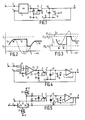
- Fig. 3 indicates how with a suitable choice of the voltages E1, E2 and E4 negative-going peak values of an input signal can be measured. Again the voltages E2 and E4 may be zero, so that the highest negative peak values of an input voltage can be determined.
Landscapes
- Physics & Mathematics (AREA)
- Engineering & Computer Science (AREA)
- Power Engineering (AREA)
- Nonlinear Science (AREA)
- General Physics & Mathematics (AREA)
- Measurement Of Current Or Voltage (AREA)
Claims (4)
Applications Claiming Priority (2)
| Application Number | Priority Date | Filing Date | Title |
|---|---|---|---|
| NL8301602 | 1983-05-06 | ||
| NL8301602A NL8301602A (nl) | 1983-05-06 | 1983-05-06 | Topdetector. |
Publications (2)
| Publication Number | Publication Date |
|---|---|
| EP0124944A1 EP0124944A1 (de) | 1984-11-14 |
| EP0124944B1 true EP0124944B1 (de) | 1987-11-25 |
Family
ID=19841813
Family Applications (1)
| Application Number | Title | Priority Date | Filing Date |
|---|---|---|---|
| EP84200631A Expired EP0124944B1 (de) | 1983-05-06 | 1984-05-03 | Spitzendetektor |
Country Status (5)
| Country | Link |
|---|---|
| US (1) | US4605867A (de) |
| EP (1) | EP0124944B1 (de) |
| JP (1) | JPS59211866A (de) |
| DE (1) | DE3467816D1 (de) |
| NL (1) | NL8301602A (de) |
Families Citing this family (13)
| Publication number | Priority date | Publication date | Assignee | Title |
|---|---|---|---|---|
| JPH0224572A (ja) * | 1988-07-13 | 1990-01-26 | Matsushita Electric Ind Co Ltd | ピークホールド回路 |
| JP2638297B2 (ja) * | 1989-12-25 | 1997-08-06 | 日本電気株式会社 | ピークレベル検出回路 |
| US5304939A (en) * | 1991-06-28 | 1994-04-19 | Digital Equipment Corporation | Tracking peak detector |
| US5362992A (en) * | 1992-06-01 | 1994-11-08 | National Semiconductor Corporation | Electronic control of peak detector response time |
| KR950009777B1 (ko) * | 1992-10-13 | 1995-08-28 | 삼성전자주식회사 | 영상기록재생장치의 기록모드 검출회로 |
| TW427051B (en) * | 1998-01-15 | 2001-03-21 | Koninkl Philips Electronics Nv | Peak detection apparatus |
| US7161392B2 (en) * | 2004-06-23 | 2007-01-09 | Teradyne, Inc. | Comparator feedback peak detector |
| JP2006211072A (ja) * | 2005-01-26 | 2006-08-10 | Sony Corp | ピークホールド回路及び電子機器 |
| US7439776B1 (en) * | 2006-04-14 | 2008-10-21 | Atheros Communications, Inc. | Technique to increase the speed of a peak detector |
| DE602006013812D1 (de) | 2006-07-25 | 2010-06-02 | St Microelectronics Srl | Vorrichtung zum Vergleich des Spitzenwertes von mindestens einer Spannung mit einer Referenzspannung |
| US20110234775A1 (en) * | 2008-10-20 | 2011-09-29 | Macnaughton Boyd | DLP Link System With Multiple Projectors and Integrated Server |
| US9599643B2 (en) * | 2011-09-29 | 2017-03-21 | Silicon Laboratories Inc. | Peak detector |
| RU2506598C1 (ru) * | 2012-07-17 | 2014-02-10 | Российская Федерация, от имени которой выступает Государственная корпорация по атомной энергии "Росатом" | Пиковый детектор |
Family Cites Families (3)
| Publication number | Priority date | Publication date | Assignee | Title |
|---|---|---|---|---|
| US3651419A (en) * | 1970-07-06 | 1972-03-21 | Rca Corp | Peak demodulator |
| DE2233488C2 (de) * | 1972-07-07 | 1974-06-06 | Siemens Ag, 1000 Berlin Und 8000 Muenchen | Demodulator-Schaltung mit einem Transistor |
| NL8001234A (nl) * | 1980-02-29 | 1981-10-01 | Philips Nv | Topdetector. |
-
1983
- 1983-05-06 NL NL8301602A patent/NL8301602A/nl not_active Application Discontinuation
-
1984
- 1984-05-03 EP EP84200631A patent/EP0124944B1/de not_active Expired
- 1984-05-03 DE DE8484200631T patent/DE3467816D1/de not_active Expired
- 1984-05-04 JP JP59090064A patent/JPS59211866A/ja active Pending
- 1984-05-04 US US06/607,335 patent/US4605867A/en not_active Expired - Fee Related
Also Published As
| Publication number | Publication date |
|---|---|
| DE3467816D1 (en) | 1988-01-07 |
| US4605867A (en) | 1986-08-12 |
| JPS59211866A (ja) | 1984-11-30 |
| EP0124944A1 (de) | 1984-11-14 |
| NL8301602A (nl) | 1984-12-03 |
Similar Documents
| Publication | Publication Date | Title |
|---|---|---|
| US5038055A (en) | Peak level detecting device and method | |
| US3985954A (en) | DC level control circuit | |
| US4052679A (en) | Phase shifting circuit | |
| US3939434A (en) | Wideband DC current amplifier | |
| US4605867A (en) | Peak detector | |
| EP0196906A2 (de) | Schaltung zur Detektion eines automatischen Verstärkungsregelungssignals | |
| US4935703A (en) | Low bias, high slew rate operational amplifier | |
| EP0484129B1 (de) | Abtast- und Halteschaltung | |
| US3694748A (en) | Peak-to-peak detector | |
| US4307305A (en) | Precision rectifier circuits | |
| US4473780A (en) | Amplifier circuit and focus voltage supply circuit incorporating such an amplifier circuit | |
| US3815048A (en) | Lc-oscillator with automatic stabilized amplitude via bias current control | |
| US5831423A (en) | Phase meter and method of providing a voltage indicative of a phase difference | |
| US3949317A (en) | Fast recovery limiting and phase inverting amplifier | |
| US5352944A (en) | Apparatus and method for producing a temperature-independent current signal in an automatic gain control circuit | |
| US4625131A (en) | Attenuator circuit | |
| US4216436A (en) | High gain differential amplifier | |
| US5239702A (en) | Tuning detector | |
| US4420698A (en) | Peak detector | |
| US3764931A (en) | Gain control circuit | |
| US4318050A (en) | AM Detecting circuit | |
| US6091294A (en) | Amplifier circuit | |
| US3983417A (en) | RF level sensing circuit | |
| US4274058A (en) | Amplifier with separate AC and DC feedback loops | |
| US3454882A (en) | Radio receiver using plural variable gain stages |
Legal Events
| Date | Code | Title | Description |
|---|---|---|---|
| PUAI | Public reference made under article 153(3) epc to a published international application that has entered the european phase |
Free format text: ORIGINAL CODE: 0009012 |
|
| AK | Designated contracting states |
Designated state(s): DE FR GB NL |
|
| 17P | Request for examination filed |
Effective date: 19841130 |
|
| GRAA | (expected) grant |
Free format text: ORIGINAL CODE: 0009210 |
|
| AK | Designated contracting states |
Kind code of ref document: B1 Designated state(s): DE FR GB NL |
|
| REF | Corresponds to: |
Ref document number: 3467816 Country of ref document: DE Date of ref document: 19880107 |
|
| ET | Fr: translation filed | ||
| PLBE | No opposition filed within time limit |
Free format text: ORIGINAL CODE: 0009261 |
|
| STAA | Information on the status of an ep patent application or granted ep patent |
Free format text: STATUS: NO OPPOSITION FILED WITHIN TIME LIMIT |
|
| 26N | No opposition filed | ||
| PGFP | Annual fee paid to national office [announced via postgrant information from national office to epo] |
Ref country code: NL Payment date: 19900531 Year of fee payment: 7 |
|
| PG25 | Lapsed in a contracting state [announced via postgrant information from national office to epo] |
Ref country code: NL Effective date: 19911201 |
|
| NLV4 | Nl: lapsed or anulled due to non-payment of the annual fee | ||
| PGFP | Annual fee paid to national office [announced via postgrant information from national office to epo] |
Ref country code: GB Payment date: 19920430 Year of fee payment: 9 |
|
| PGFP | Annual fee paid to national office [announced via postgrant information from national office to epo] |
Ref country code: FR Payment date: 19920519 Year of fee payment: 9 |
|
| PGFP | Annual fee paid to national office [announced via postgrant information from national office to epo] |
Ref country code: DE Payment date: 19920724 Year of fee payment: 9 |
|
| PG25 | Lapsed in a contracting state [announced via postgrant information from national office to epo] |
Ref country code: GB Effective date: 19930503 |
|
| GBPC | Gb: european patent ceased through non-payment of renewal fee |
Effective date: 19930503 |
|
| PG25 | Lapsed in a contracting state [announced via postgrant information from national office to epo] |
Ref country code: FR Effective date: 19940131 |
|
| PG25 | Lapsed in a contracting state [announced via postgrant information from national office to epo] |
Ref country code: DE Effective date: 19940201 |
|
| REG | Reference to a national code |
Ref country code: FR Ref legal event code: ST |