EP0124962B1 - Procédé et outil pour effectuer manuellement un enroulement de réserve de fil - Google Patents
Procédé et outil pour effectuer manuellement un enroulement de réserve de fil Download PDFInfo
- Publication number
- EP0124962B1 EP0124962B1 EP84301342A EP84301342A EP0124962B1 EP 0124962 B1 EP0124962 B1 EP 0124962B1 EP 84301342 A EP84301342 A EP 84301342A EP 84301342 A EP84301342 A EP 84301342A EP 0124962 B1 EP0124962 B1 EP 0124962B1
- Authority
- EP
- European Patent Office
- Prior art keywords
- yarn
- traverse
- tool
- core
- support core
- Prior art date
- Legal status (The legal status is an assumption and is not a legal conclusion. Google has not performed a legal analysis and makes no representation as to the accuracy of the status listed.)
- Expired
Links
- 238000004804 winding Methods 0.000 title claims description 18
- 238000000034 method Methods 0.000 title claims description 4
- 230000015572 biosynthetic process Effects 0.000 claims description 7
- 230000000694 effects Effects 0.000 claims description 4
- 210000003414 extremity Anatomy 0.000 description 5
- 239000002699 waste material Substances 0.000 description 2
- 230000009471 action Effects 0.000 description 1
- 230000004888 barrier function Effects 0.000 description 1
- 230000008901 benefit Effects 0.000 description 1
- 230000008859 change Effects 0.000 description 1
- 230000004044 response Effects 0.000 description 1
- 210000001364 upper extremity Anatomy 0.000 description 1
Images

Classifications
-
- B—PERFORMING OPERATIONS; TRANSPORTING
- B65—CONVEYING; PACKING; STORING; HANDLING THIN OR FILAMENTARY MATERIAL
- B65H—HANDLING THIN OR FILAMENTARY MATERIAL, e.g. SHEETS, WEBS, CABLES
- B65H54/00—Winding, coiling, or depositing filamentary material
- B65H54/70—Other constructional features of yarn-winding machines
-
- B—PERFORMING OPERATIONS; TRANSPORTING
- B65—CONVEYING; PACKING; STORING; HANDLING THIN OR FILAMENTARY MATERIAL
- B65H—HANDLING THIN OR FILAMENTARY MATERIAL, e.g. SHEETS, WEBS, CABLES
- B65H54/00—Winding, coiling, or depositing filamentary material
- B65H54/02—Winding and traversing material on to reels, bobbins, tubes, or like package cores or formers
- B65H54/28—Traversing devices; Package-shaping arrangements
- B65H54/34—Traversing devices; Package-shaping arrangements for laying subsidiary winding, e.g. transfer tails
- B65H54/343—Traversing devices; Package-shaping arrangements for laying subsidiary winding, e.g. transfer tails when starting winding on an empty bobbin
-
- B—PERFORMING OPERATIONS; TRANSPORTING
- B65—CONVEYING; PACKING; STORING; HANDLING THIN OR FILAMENTARY MATERIAL
- B65H—HANDLING THIN OR FILAMENTARY MATERIAL, e.g. SHEETS, WEBS, CABLES
- B65H2701/00—Handled material; Storage means
- B65H2701/30—Handled filamentary material
- B65H2701/31—Textiles threads or artificial strands of filaments
Definitions
- the present invention relates to a winding yarn, and in particular to the reliable formation of a tail at the start of winding up a fresh package.
- DE-A-2705392 discloses a hand-held tool for forming a tail on a rotating yarn support core, comprising: means for positioning the tool in an operative position relative to a rotatable yarn supporting core; and means for holding a run of a yarn against the support core for effecting traverse in a first direction.
- the tool Upon completion of the reserve, the tool is moved away to allow the further wound yarn to commence the first layer of package build-up.
- the tail, the yarn reserve, and the first layer of the package are in this reference all formed by a traverse in a single direction along the support core.
- GB-A-1471472 discloses an automatic yarn reserve builder which is actuated in response to a change of bobbins, and in Figures 5 and 6 there is disclosure of a system which will automatically build the reserve during a preliminary partial traverse in a direction opposed to the direction of traverse common to the transfer tail attachment traverse and the first main traverse of the yarn guide during winding of the main package. This forms a so-called “trapped” or "protected” tail in which the tail end is under the reserve.
- This prior art thus discloses a method of forming a tail on a rotating yarn support core during yarn winding comprising: holding a run of the yarn against the support core for effecting traverse in a first direction; winding the yarn onto the end of the core, starting from the end of the tail, in said first direction of traverse; forming a reserve by winding the yarn in a second direction of traverse opposite to said first direction; and releasing the yarn to start winding of a yarn package in the first direction of traverse.
- such a method is characterised by placing a hand-held tool in position alongside the rotatable yarn support core ready for operation, the tool including means for holding the run of the yarn in contact with said tool when so positioned; manually operating movable means of the yarn run holding means by use of a manually operable control of the tool for guiding that run of a yarn for traverse in the second direction during formation of the yarn reserve on the core and for then allowing release of the yarn when winding of the yarn package is started by a traverse in the first direction.
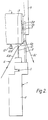
- the yarn support core 1 has at its end yarn pick-up slots 3 intended to pick up the yarn to define the end of the tail.
- the yarn support core 1 is caused to rotate, in the anticlockwise direction as viewed in Figure 1, by frictional contact with the take-up roll 4 alongside it.
- it is mounted on a swinging package arm 5 allowing it to be moved towards and away from the take-up roll 4.
- This same swinging action of the package arm 5 also allows the yarn support core 1 to move further away from the axis of rotation of the take-up roll 4 as the yarn package (not shown) builds up on the cylindrical surface of the core 1.
- Yarn 6 is initially threaded up with the aid of a "tailing" tool 7 having a handle 8, a main hook 9, and a secondary hook 10, the latter being threadable and controlled by a lever 11 fixed to it.
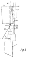
- Figure 2 also shows a yarn traverse guide 12 which oscillates to-and-fro in a direction parallel to the axis of the yarn support core 1 so as to cause the yarn package to build up on the core 1 in a controlled manner with the appopriate overall profile of the package (usually requiring the first layers of the package to extend closer to the ends of the yarn support core 1 than the later layers so that the package has a stable, tapered profile).
- the yarn pick-up slot 3 is the one visible on the lefthand side of Figure 1 and it will be clear that during rotation of the yarn support core 1 that slot 3 will eventually (after a quarter of a revolution) come into register with the run of yarn 6 guided between the main and secondary hooks of the "tailing" tool 7.
- the yarn 6 can be considered as three spearate runs 6a, 6b and 6c, along which any point on the continous yarn will travel.
- the run 6a is from the delivery to the secondary hook 10
- the run 6b is from the secondary hook 10 to a guide bar 9a of the main hook 9
- the run 6c extends from the main hook 9 to a waste suction tube (not shown).
- the yarn run 6b Upon rotation of the yarn support core 1, the yarn run 6b will initially ride on the end surface of the yarn support core 1 but as soon as one of the two pick-up slots 3 comes into register with it it will be entrained by that slot 3 and rapidly severed somewhere between that point of catching in the slot 3 and the waste suction tube (probably along the run 6c).
- the yarn support core 1 includes chamfers 3a around the pick-up slot 3, so as to guide the loose severed end of the yarn into the slot 3 where the end will be held to prevent flaying during winding.
- the axis of rotation 10c of the secondary hook 10 lies in the plane of the U of the yarn locating portion 10a and intersects the limbs of the U at locations spaced from their ends adjacent the bight of the U so, as the secondary hook 10 rotates, the bight and preferably at least an adjacent part of each limb will orbit the hook axis of rotation to traverse the tail yarn rightwardly and then allow the yarn run 6a to release itself automatically from the secondary hook 10 and to move across to be entrained by the traversing guide 12 ( Figure 2).
- tail 15 is initially formed by a tail run 15a which extends from the pick-up slot 3 as far as the initial line (13 in Figure 2) and subsequently the build-up of the tail 15 traverses back over the top of this run 15a and helps to lock the run 15a in place. Consequently, use of the "tailing" tool in accordance with the present invention allows the tail to have its first convolution or convolutions trapped by the subsequently formed convolutions wound thereon, leaving the finished tail stable. The resulting package is therefore more easily handled and requires less care to be taken during storage.
- the main hook 9 of the tool has an end 9b which co-operates with the bracket 5 to locate the tool in the correct position (a) axially of the yarn support core 1 so as to maintain the geometry illustrated in Figure 1, and (b) radially of the yarn support core axis so as to maintain the geometry of the Figure 2 position.
- the important characteristic of the "tailing" tool 7 is that it should incorporate means for shifting the tailing line axially of the yarn support core 1, during tail formation in a direction to trap the initial yarn tail convolution or convolutions.
Landscapes
- Engineering & Computer Science (AREA)
- Textile Engineering (AREA)
- Winding Filamentary Materials (AREA)
- Yarns And Mechanical Finishing Of Yarns Or Ropes (AREA)
- Guides For Winding Or Rewinding, Or Guides For Filamentary Materials (AREA)
- Replacing, Conveying, And Pick-Finding For Filamentary Materials (AREA)
Claims (6)
Priority Applications (1)
| Application Number | Priority Date | Filing Date | Title |
|---|---|---|---|
| AT84301342T ATE25064T1 (de) | 1983-04-27 | 1984-03-01 | Verfahren und handgeraet zum manuellen bilden einer fadenreservewicklung. |
Applications Claiming Priority (2)
| Application Number | Priority Date | Filing Date | Title |
|---|---|---|---|
| GB8311513 | 1983-04-27 | ||
| GB838311513A GB8311513D0 (en) | 1983-04-27 | 1983-04-27 | Yarn winding |
Publications (2)
| Publication Number | Publication Date |
|---|---|
| EP0124962A1 EP0124962A1 (fr) | 1984-11-14 |
| EP0124962B1 true EP0124962B1 (fr) | 1987-01-21 |
Family
ID=10541793
Family Applications (1)
| Application Number | Title | Priority Date | Filing Date |
|---|---|---|---|
| EP84301342A Expired EP0124962B1 (fr) | 1983-04-27 | 1984-03-01 | Procédé et outil pour effectuer manuellement un enroulement de réserve de fil |
Country Status (5)
| Country | Link |
|---|---|
| EP (1) | EP0124962B1 (fr) |
| KR (1) | KR840008638A (fr) |
| AT (1) | ATE25064T1 (fr) |
| DE (1) | DE3462120D1 (fr) |
| GB (1) | GB8311513D0 (fr) |
Families Citing this family (1)
| Publication number | Priority date | Publication date | Assignee | Title |
|---|---|---|---|---|
| DE3607342A1 (de) * | 1986-03-06 | 1987-09-10 | Schuster & Co F M N | Vorrichtung zum bilden einer fadenreserve beim anspulen eines fadens auf einer spulenhuelse |
Family Cites Families (4)
| Publication number | Priority date | Publication date | Assignee | Title |
|---|---|---|---|---|
| US3971518A (en) * | 1974-11-18 | 1976-07-27 | Eastman Kodak Company | Transfer tail apparatus for use with textile yarn winders |
| DE2705392A1 (de) * | 1977-02-09 | 1978-08-10 | Luwa Ag | Verfahren und vorrichtung zum anschluss eines garns und zur bildung einer garnreserve auf einer garnhuelse |
| CH626858A5 (fr) * | 1978-03-21 | 1981-12-15 | Rieter Ag Maschf | |
| DE2826392C2 (de) * | 1978-06-16 | 1980-01-17 | Zinser Textilmaschinen Gmbh, 7333 Ebersbach | Einrichtung zum Aufwinden einer Fadenreservewicklung |
-
1983
- 1983-04-27 GB GB838311513A patent/GB8311513D0/en active Pending
-
1984
- 1984-03-01 AT AT84301342T patent/ATE25064T1/de not_active IP Right Cessation
- 1984-03-01 EP EP84301342A patent/EP0124962B1/fr not_active Expired
- 1984-03-01 DE DE8484301342T patent/DE3462120D1/de not_active Expired
- 1984-03-30 KR KR1019840001676A patent/KR840008638A/ko not_active Withdrawn
Also Published As
| Publication number | Publication date |
|---|---|
| GB8311513D0 (en) | 1983-06-02 |
| DE3462120D1 (en) | 1987-02-26 |
| EP0124962A1 (fr) | 1984-11-14 |
| ATE25064T1 (de) | 1987-02-15 |
| KR840008638A (ko) | 1984-12-17 |
Similar Documents
| Publication | Publication Date | Title |
|---|---|---|
| US3967795A (en) | Bobbin tube | |
| EP0057525B1 (fr) | Machine à bobiner pour fil textile | |
| EP0157654B1 (fr) | Procédé et dispositif pour le changement automatique de bobines sur un bobinoir | |
| JPH0221485Y2 (fr) | ||
| US3251560A (en) | Winding machine | |
| EP0846641B1 (fr) | Unité de bobinage d'une machine textile pour la fabrication de bobines à spires croisées | |
| US3913853A (en) | Automatic winding machine | |
| US3184174A (en) | Yarn-spool winding machine with automatic spool-exchanging device | |
| US3136494A (en) | Method and means for preparing spinning cops for rewinding | |
| US4093135A (en) | Device for controlling a reserve winding when winding thread on a spool or core | |
| EP0847952B1 (fr) | Bobinoir pour un fil élastique | |
| US4352466A (en) | Device for making a thread reserve | |
| JP2637169B2 (ja) | 予備系を形成するための方法及び装置 | |
| EP0124962A1 (fr) | Procédé et outil pour effectuer manuellement un enroulement de réserve de fil | |
| US3153513A (en) | Apparatus for readying the yarn end portion of bobbins in textile machines | |
| US3042328A (en) | Spooler type winder | |
| US5133514A (en) | Yarn processing method for tail end | |
| JP2584134Y2 (ja) | 線材の連続巻取装置 | |
| USRE33111E (en) | Method and apparatus for automatically doffing and donning take-up packages on a winder | |
| JPS58109365A (ja) | 巻き取り装置 | |
| JPH0416390B2 (fr) | ||
| EP1129976B1 (fr) | Paquet de fil textile élastique et proçédé de fonctionnement d'un bobinoir pour fils textiles élastiques | |
| US3999716A (en) | Transfer tail apparatus for use with textile yarn winders | |
| EP0025507B1 (fr) | Bras pivotant pour bobineuse | |
| US4093134A (en) | Method and apparatus to reduce waste yarn during tie-up of yarn winders |
Legal Events
| Date | Code | Title | Description |
|---|---|---|---|
| PUAI | Public reference made under article 153(3) epc to a published international application that has entered the european phase |
Free format text: ORIGINAL CODE: 0009012 |
|
| AK | Designated contracting states |
Designated state(s): AT CH DE FR GB IT LI |
|
| 17P | Request for examination filed |
Effective date: 19841119 |
|
| GRAA | (expected) grant |
Free format text: ORIGINAL CODE: 0009210 |
|
| AK | Designated contracting states |
Kind code of ref document: B1 Designated state(s): AT CH DE FR GB IT LI |
|
| REF | Corresponds to: |
Ref document number: 25064 Country of ref document: AT Date of ref document: 19870215 Kind code of ref document: T |
|
| REF | Corresponds to: |
Ref document number: 3462120 Country of ref document: DE Date of ref document: 19870226 |
|
| ET | Fr: translation filed | ||
| ITF | It: translation for a ep patent filed | ||
| PLBE | No opposition filed within time limit |
Free format text: ORIGINAL CODE: 0009261 |
|
| STAA | Information on the status of an ep patent application or granted ep patent |
Free format text: STATUS: NO OPPOSITION FILED WITHIN TIME LIMIT |
|
| 26N | No opposition filed | ||
| ITTA | It: last paid annual fee | ||
| PGFP | Annual fee paid to national office [announced via postgrant information from national office to epo] |
Ref country code: FR Payment date: 19940209 Year of fee payment: 11 |
|
| PGFP | Annual fee paid to national office [announced via postgrant information from national office to epo] |
Ref country code: CH Payment date: 19940211 Year of fee payment: 11 |
|
| PGFP | Annual fee paid to national office [announced via postgrant information from national office to epo] |
Ref country code: AT Payment date: 19940214 Year of fee payment: 11 |
|
| PGFP | Annual fee paid to national office [announced via postgrant information from national office to epo] |
Ref country code: GB Payment date: 19940216 Year of fee payment: 11 |
|
| PGFP | Annual fee paid to national office [announced via postgrant information from national office to epo] |
Ref country code: DE Payment date: 19940217 Year of fee payment: 11 |
|
| PG25 | Lapsed in a contracting state [announced via postgrant information from national office to epo] |
Ref country code: GB Effective date: 19950301 Ref country code: AT Effective date: 19950301 |
|
| PG25 | Lapsed in a contracting state [announced via postgrant information from national office to epo] |
Ref country code: LI Effective date: 19950331 Ref country code: CH Effective date: 19950331 |
|
| GBPC | Gb: european patent ceased through non-payment of renewal fee |
Effective date: 19950301 |
|
| PG25 | Lapsed in a contracting state [announced via postgrant information from national office to epo] |
Ref country code: FR Free format text: LAPSE BECAUSE OF NON-PAYMENT OF DUE FEES Effective date: 19951130 |
|
| REG | Reference to a national code |
Ref country code: CH Ref legal event code: PL |
|
| PG25 | Lapsed in a contracting state [announced via postgrant information from national office to epo] |
Ref country code: DE Effective date: 19951201 |
|
| REG | Reference to a national code |
Ref country code: FR Ref legal event code: ST |