EP0124967A1 - Circuits transformateurs de courant continu - Google Patents
Circuits transformateurs de courant continu Download PDFInfo
- Publication number
- EP0124967A1 EP0124967A1 EP84301501A EP84301501A EP0124967A1 EP 0124967 A1 EP0124967 A1 EP 0124967A1 EP 84301501 A EP84301501 A EP 84301501A EP 84301501 A EP84301501 A EP 84301501A EP 0124967 A1 EP0124967 A1 EP 0124967A1
- Authority
- EP
- European Patent Office
- Prior art keywords
- current
- phase
- alternating
- circuit arrangement
- voltage
- Prior art date
- Legal status (The legal status is an assumption and is not a legal conclusion. Google has not performed a legal analysis and makes no representation as to the accuracy of the status listed.)
- Granted
Links
- 238000004804 winding Methods 0.000 claims abstract description 35
- 230000004044 response Effects 0.000 claims description 7
- 230000001419 dependent effect Effects 0.000 claims description 3
- 230000004907 flux Effects 0.000 description 4
- 239000003990 capacitor Substances 0.000 description 2
- 238000010586 diagram Methods 0.000 description 2
- 230000000694 effects Effects 0.000 description 2
- 230000010354 integration Effects 0.000 description 2
- 239000004065 semiconductor Substances 0.000 description 2
- 230000003068 static effect Effects 0.000 description 2
- 230000008859 change Effects 0.000 description 1
- 239000004020 conductor Substances 0.000 description 1
- 230000007547 defect Effects 0.000 description 1
- 230000001627 detrimental effect Effects 0.000 description 1
- 230000008030 elimination Effects 0.000 description 1
- 238000003379 elimination reaction Methods 0.000 description 1
- 238000001914 filtration Methods 0.000 description 1
- 238000009499 grossing Methods 0.000 description 1
- 238000005259 measurement Methods 0.000 description 1
- 238000000034 method Methods 0.000 description 1
- 230000001681 protective effect Effects 0.000 description 1
- 229920006395 saturated elastomer Polymers 0.000 description 1
- 238000009738 saturating Methods 0.000 description 1
- 230000007704 transition Effects 0.000 description 1
Images


Classifications
-
- G—PHYSICS
- G01—MEASURING; TESTING
- G01R—MEASURING ELECTRIC VARIABLES; MEASURING MAGNETIC VARIABLES
- G01R15/00—Details of measuring arrangements of the types provided for in groups G01R17/00 - G01R29/00, G01R33/00 - G01R33/26 or G01R35/00
- G01R15/14—Adaptations providing voltage or current isolation, e.g. for high-voltage or high-current networks
- G01R15/18—Adaptations providing voltage or current isolation, e.g. for high-voltage or high-current networks using inductive devices, e.g. transformers
- G01R15/183—Adaptations providing voltage or current isolation, e.g. for high-voltage or high-current networks using inductive devices, e.g. transformers using transformers with a magnetic core
- G01R15/185—Adaptations providing voltage or current isolation, e.g. for high-voltage or high-current networks using inductive devices, e.g. transformers using transformers with a magnetic core with compensation or feedback windings or interacting coils, e.g. 0-flux sensors
-
- G—PHYSICS
- G01—MEASURING; TESTING
- G01R—MEASURING ELECTRIC VARIABLES; MEASURING MAGNETIC VARIABLES
- G01R19/00—Arrangements for measuring currents or voltages or for indicating presence or sign thereof
- G01R19/14—Indicating direction of current; Indicating polarity of voltage
Definitions
- the present invention relates to circuit arrangements incorporating D.C. current transformers.
- Such transformers comprise a pair of interconnected electrical windings (subsequently referred to as secondary windings) magnetically linked to respective independently saturable cores which are in turn adapted to be magnetically linked to a common circuit in which an unknown direct current flows, the arrangement of cores and windings being such that any current passed through the interconnected secondary windings tends to augment the flux produced by the D.C. in one core and to oppose the corresponding flux in the other core.
- the secondary windings are connected in opposite senses in series.
- each core is in the form of a laminated ring, which, in use, encircles a conductor in the D.C. circuit which thus forms a single turn primary winding common to the respective secondary windings.
- the secondary current is A.C. of substantially square waveform, and that the ratio of the primary to the secondary current is inversely proportional to the primary: secondary turns ratio, even though the current in the primary is D.C.. D.C. current transformers thus exhibit true transformer characteristics, although their mode of operation is different from conventional A.C. transformer operation.
- D.C. current transformer circuit arrangements have provided only an indication of the absolute magnitude of the D.C. in the primary circuit, ⁇ and not an indication of its sense.
- An object of the present invention is to overcome this defect. It.will be appreciated that conventional magnetic arrangements for indicating the sense of the unknown D.C. will generally be precluded for the same reasons that dictate the use of a current transformer in the first place.
- a D.C.current transformer measuring circuit arrangement comprises a D.C. current transformer (CT) provided with a pair of interconnected secondary windings (Wl,W2),signal means (El) for applying an alternating e.m.f. acorss the free ends of said windings and means (T,R) for measuring the resulting alternating current in said windings, characterised in that phase-sensitive means (2) are provided for determining the phase with respect to said alternating e.m.f. of the voltage, (Vl, V2) across at least one of said secondary windings and thereby providing an indication of the sense of the current (Il) through the primary (B) of said D.C. current transformer.
- CT D.C. current transformer
- Wl,W2 interconnected secondary windings
- El signal means
- T,R for measuring the resulting alternating current in said windings
- the phase-sensitive means senses said voltage at least once per cycle of said alternating e.m.f.
- the inte grating means is periodically re-set immediately after the core associated with said winding de-saturates.
- the voltage sensing means sums the voltages across the secondary windings. This enables the voltage sensing means to detect a reversal of the measured D.C. within one half-cycle of the signal means. Such a rapid response time is useful in D.C. motor control applications, for example.
- the arrangement shown generally comprises a known D.C. current transformer measuring circuit arrangement 1, a polarity sensing circuit arrangement 2 and a gain-reversible amplifier circuit 2A.
- Circuit arrangement 1 comprises a D.C. current transformer CT consisting of two magnetically saturable ring cores Cl and C2 on which respective windings Wl and W2 are wound and connected in series so as to tend to generate m.m.f.'s, which respectively oppose and augment any m.m.f. generated by a current in a central busbar B.
- Cores Cl and C2 are each shown encircling busbar B which carries a current Il (typically of hundreds or even thousands of amps).
- busbar B forms a single turn primary common to secondary windings Wl and W2.
- the secondary circuit of current transformer CT incorporates a low impedance signal source El which generates an alternating e.m.f.E, typically at 200V, 50 or 60Hz.
- the secondary circuit is coupled by a transformer T to a bridge rectifier R which generates a current 13 in load resistor Rl.
- I3 is measured by a conventional ammeter (not shown) and can be shown to be directly proportional to I1 if certain conditions are satisfied.
- the sense of I3 is independent of the sense of I1 however; the latter is detected by polarity-sensing circuit 2 and output as a positive or negative D.C. signal by gain-reversible amplifier circuit 2A.
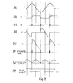
- circuit arrangement 1 may be ' understood by reference to plots a), b), c), d) and e) of Figure 2, which show respectively the waveforms of the e.m.f.E of source El, the current I2 in the secondary circuit of current transformer CT, the current I3 in load resistor Rl and the voltages VI and V2 developed across secondary windings Wl and W2.
- e.m.f.E The amplitude of e.m.f.E is chosen to be sufficiently low that the resulting flux in cores Cl and C2 is insufficient to saturate them in the absence of current in busbar B.
- windings Wl and W2 would merely behave as high inductances and waveform I2 would be a sine wave of negligible amplitude lagging E by 90°.
- current II generates m.m.f.'s in cores Cl and C2 which tend to saturate both cores but in opposite senses.
- Polarity sensing circuit 2 utilises Vl and V2 in order to determine the direction of current Il. It should be noted that if current Il flows in the reverse direction to that shown, I2 will be unaffected. However in each half cycle of 12, the core which is saturated will be that which reinforces the flux due to I1. Since Vl and V2 are developed across the unsaturated core, waveforms Vl and V2 will interchange (and furthermore, be it noted, will undergo'a 180° phase change) when Il reverses.
- Adder 3 sums Vl and V2, the common terminal of Wl and W2 being earthed and taken as a reference point. It should be noted that the output of adder 3 will reverse when Il reverses.
- the output of adder 3 is integrated by integrator 4 which is reset at each zero crossing point of 12, the integration thus senduring for one half cycle.
- the polarity of the output of integrator 4 is dependent on the phase of the output signal from adder 3 and hence on the direction of Il.
- This output is filtered by low-pass filter 5 and applied to level detector 6 which generates a corresponding two- level logic signal, dependent on whether the output of filter 5 is positive or negative.
- signal outputs are available respectively as voltages across R L (or current in it) proportional to input current magnitude, and a 2-level logic signal indicating polarity. This may suffice for simple applications.
- the magnitude signal I3 may be smoothed (to reduce the effect of.the notches in Figure 2c) and applied to an anlogue to digital converter (not shown), which delivers a digital output to operate an illuminated numerical display; the polarity signal from level detector 6 may be used to illuminate + or - symbols preceding the numerical display.
- an analogue output having true polarity may be required. This may be obtained by taking output from the magnitude signal.12 via reversing switches on an electromagnetic relay having its coil switched by the polarity signal.
- the relay may preferably be of the static type having . semiconductor switches controlled directly from the output level detector 6.
- output is taken from the magnitude output 13 via an amplifier circuit 2A having a gain switchable from +1 to -1 by the polarity logic signal.
- the amplifier circuit 2A comprises a differential operational amplifier 14 of high gain, with equal gain control resistors R 4 and R 5 ; its gain is switched via a change-over switch 15 controlled by relay coil 16.
- the electromechanical relay may advantageously be replaced by an equivalent static semiconductor switch.
- the positive and negative amplifier gains may be made of equal magnitude other than the unity value shown, by known methods.
- Integrator 4 is re-set by pulses as shown in Figure 2f. These are generated by re-set circuit 7 in which a second auxiliary voltage source E 3 in phase quadrature to E 1 is connected via a level detector 8 which delivers a square wave output having transitions at the zero crossings of E 3 .
- Two differentiating circuits 9, 10 are connected respectively directly to the output of 8, and via a logic reverse circuit 11 to generate short pulses. The combination of the short pulse outputs of 9, 10 via OR-gate 12 (shown in the waveform of Figure 2(f)) then provides the desired integrator reset pulses.
- the invention includes within its scope polarity sensing circuit arrangements which merely rely on sensing one or other of Vl and V2 (although the response time is minimised if both are sensed) and that means for determining the phase of Vl and or V2 other than integrators may be used. Furthermore it will be apparent that integration periods longer than one half cycle may be employed (preferably still with 12-determined starting points), although the arrangement illustrated has particular advantages of simplicity, rapid response time, and reliability.
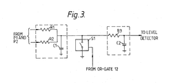
- FIG. 3 A simple implementation of elements 3, 4, 5 of Figure 1 is shown in Figure 3 in which voltages Vl and V2 are combined via equal resistors R3, R4 and integrated by capacitor Cl.
- the low-pass filter 5 comprises resistor R3 and capacitor C2. Reset of the integrator is by momentary closure of electronic switch Sl.
- the respective a.c. secondary currents are identical trapezoids as before ( Figure 2b) but at 90° relative phase. Because of the series bridge connection the current 13 to the burden resistor is unidirectional and equal to the highest magnitude of either of the a.c. currents from the auxiliary current transformers at every instant; it is therefore smooth d.c., with an ampere-turn balance relationship to main primary current I I . The elimination of notches removes i the necessity to provide a smoothing filter, with its attendant lag, and substantially improves accuracy.
- a polarity-sensing circuit may be applied to the 4-core current transformer, as shown in Figure 4.
- the respective pairs of main current transformer cores are Cl, C2 and C3, C4 (shown schematically), supplied by auxiliary voltages E 1 E 2 respectively, in phase quadrature.
- the winding voltages are Vl, V2 and V3, V4 respectively, which are summated by summers 3, 17 and integrated by integrators 4, 18.
- the outputs of the integrators are combined via equal resistors R6 R7 and applied to a level detector 6 as before, but without the low-pass filter 5.
- Integrator reset signals are applied to 4 via circuit 7 as before and to 18 via identical circuit 14.
- the inputs to 7, 14 are from E2 and El respectively via isolating transformers 19, 20.
- the waveform applied to level detector 6 for positive input current has a 4-phase ripple but is wholly positive at every instant, giving a steady logic level output from 6 indicating positive polarity.
- the input to 6 reverses, and the output of 6 changes its logic level to that indicating negative polarity.
- the low-pass filter is omitted in this circuit, the response of the polarity indication signal is fast, within about a half cycle of current reversal, which gives an improved response for control and other applications.
- the reversing arrangements of Figures 4 or 5 may be applied to the output as before.
- the principles of the 4-core arrangement may be applied also to a 6-core arrangement.
- the three pairs of current transformers are supplied by auxiliary coltages at relative phase angles of 0°, 120° and 240°, i.e. from 3-phase supply.
- auxiliary coltages at relative phase angles of 0°, 120° and 240°, i.e. from 3-phase supply.
- integrators with outputs combined as before.
- reset circuits similar to 7 but supplied with voltages each in quadrature to the respective main auxiliary voltages, obtained from suitable windings on a 3-phase transformer.
Landscapes
- Engineering & Computer Science (AREA)
- Power Engineering (AREA)
- Physics & Mathematics (AREA)
- General Physics & Mathematics (AREA)
- Measurement Of Current Or Voltage (AREA)
- Measuring Instrument Details And Bridges, And Automatic Balancing Devices (AREA)
Applications Claiming Priority (2)
| Application Number | Priority Date | Filing Date | Title |
|---|---|---|---|
| GB8309559 | 1983-04-08 | ||
| GB838309559A GB8309559D0 (en) | 1983-04-08 | 1983-04-08 | Dc current transformer circuits |
Publications (2)
| Publication Number | Publication Date |
|---|---|
| EP0124967A1 true EP0124967A1 (fr) | 1984-11-14 |
| EP0124967B1 EP0124967B1 (fr) | 1987-05-20 |
Family
ID=10540808
Family Applications (1)
| Application Number | Title | Priority Date | Filing Date |
|---|---|---|---|
| EP84301501A Expired EP0124967B1 (fr) | 1983-04-08 | 1984-03-07 | Circuits transformateurs de courant continu |
Country Status (4)
| Country | Link |
|---|---|
| US (1) | US4626777A (fr) |
| EP (1) | EP0124967B1 (fr) |
| DE (1) | DE3463850D1 (fr) |
| GB (1) | GB8309559D0 (fr) |
Cited By (1)
| Publication number | Priority date | Publication date | Assignee | Title |
|---|---|---|---|---|
| FR2639121A1 (fr) * | 1988-11-14 | 1990-05-18 | Caen Claude | Dispositif de mesure de courant continu bidirectionnel, a isolement galvanique et large bande passante |
Families Citing this family (14)
| Publication number | Priority date | Publication date | Assignee | Title |
|---|---|---|---|---|
| US4794794A (en) * | 1986-10-30 | 1989-01-03 | Djorup Robert Sonny | Thermal anemometer |
| DE3827758C2 (de) * | 1988-08-16 | 1996-08-29 | Bayerische Motoren Werke Ag | Einrichtung zur Überwachung einer vorgegebenen Stromstärke in mindestens einem elektrischen Leiter |
| US5196784A (en) * | 1991-03-18 | 1993-03-23 | Hughes Aircraft Company | Isolated current monitoring circuit for measuring direct and high duty factor currents |
| DE4128989C2 (de) * | 1991-08-31 | 1995-04-27 | Forschungsvereinigung Antriebs | Stromsensor |
| DE4327130C2 (de) * | 1993-08-12 | 1997-01-23 | Siemens Ag | Vorrichtung zur Stromerfassung bei Leitungen |
| US6114847A (en) * | 1995-10-04 | 2000-09-05 | Johnson; Darrell | Connectionless signal detection device for conductive cables |
| US6040689A (en) * | 1997-06-17 | 2000-03-21 | Ssac, Inc. | Current sensing method and apparatus |
| US6531862B1 (en) * | 1999-12-30 | 2003-03-11 | Harman International Industries, Incorporated | High performance current sensor using low cost current transformer arrays |
| KR100364821B1 (ko) * | 2000-01-31 | 2002-12-16 | 엘지산전 주식회사 | 변류기의 신호 변환 장치 |
| US7145321B2 (en) * | 2005-02-25 | 2006-12-05 | Sandquist David A | Current sensor with magnetic toroid |
| JP2013124875A (ja) | 2011-12-13 | 2013-06-24 | Japan Aviation Electronics Industry Ltd | 電流センサ |
| US9588149B2 (en) * | 2014-07-03 | 2017-03-07 | Landis+Gyr, Inc. | Method and apparatus for detecting and compensating measurement errors due to transformer saturation in a meter |
| US9618541B1 (en) * | 2016-04-20 | 2017-04-11 | Neilsen-Kuljian, Inc. | Apparatus, method and device for sensing DC currents |
| JP2026028444A (ja) * | 2024-08-07 | 2026-02-20 | 株式会社Gsユアサ | ゼロ電流センサ及び電源回路 |
Citations (3)
| Publication number | Priority date | Publication date | Assignee | Title |
|---|---|---|---|---|
| DE1250547B (de) * | 1967-09-21 | Zävody prumyslove automatisace, närodni podnik, Prag | Transduktor-Meßwandler mit richtungsabhängiger Steuerkennlinie | |
| DE1516103A1 (de) * | 1965-07-26 | 1969-07-03 | Licentia Gmbh | Gleichstromwandler |
| DE3132800A1 (de) * | 1980-08-19 | 1982-04-15 | Hitachi, Ltd., Tokyo | Strommessgeraet mit magnetischer verstaerkung |
Family Cites Families (13)
| Publication number | Priority date | Publication date | Assignee | Title |
|---|---|---|---|---|
| GB552815A (en) * | 1941-11-12 | 1943-04-27 | British Thomson Houston Co Ltd | Improvements relating to electric transformers |
| US2509738A (en) * | 1948-05-29 | 1950-05-30 | Gen Electric | Balanced magnetic amplifier |
| US2657281A (en) * | 1950-02-15 | 1953-10-27 | Ward Leonard Electric Co | Electromagnetic audio amplifier |
| US2892155A (en) * | 1954-08-09 | 1959-06-23 | Westinghouse Electric Corp | Apparatus responsive to direct quantities |
| US3105154A (en) * | 1960-01-20 | 1963-09-24 | Daystrom Inc | Blocking oscillator comparator |
| US3135911A (en) * | 1963-11-15 | 1964-06-02 | Magnetics Inc | Polarity sensitive saturable core reactor |
| US3351851A (en) * | 1964-06-26 | 1967-11-07 | Foxboro Co | Balanced magnetic amplification and process control apparatus |
| GB1084566A (en) * | 1965-04-14 | 1967-09-27 | Zd Y Prumyslove Automatisace | Transductor sensing device for the measurement of direct current and indication of the polarity thereof |
| US3500195A (en) * | 1967-06-20 | 1970-03-10 | Westinghouse Electric Corp | Current transductor having instantaneous response |
| US3699442A (en) * | 1971-05-25 | 1972-10-17 | Westinghouse Electric Corp | Bi-directional signal detector with input/output isolation |
| US3855528A (en) * | 1973-04-06 | 1974-12-17 | Lorain Prod Corp | D-c current measuring circuit |
| SU759964A1 (ru) * | 1976-07-19 | 1980-08-30 | Ryazanskij Radiotekhnicheskij | Счетчик ампер-часов 1 |
| DE3071179D1 (en) * | 1980-12-19 | 1985-11-14 | United Technologies Corp | Dual core magnetic amplifier sensor |
-
1983
- 1983-04-08 GB GB838309559A patent/GB8309559D0/en active Pending
-
1984
- 1984-03-07 EP EP84301501A patent/EP0124967B1/fr not_active Expired
- 1984-03-07 DE DE8484301501T patent/DE3463850D1/de not_active Expired
- 1984-03-19 US US06/590,908 patent/US4626777A/en not_active Expired - Fee Related
Patent Citations (3)
| Publication number | Priority date | Publication date | Assignee | Title |
|---|---|---|---|---|
| DE1250547B (de) * | 1967-09-21 | Zävody prumyslove automatisace, närodni podnik, Prag | Transduktor-Meßwandler mit richtungsabhängiger Steuerkennlinie | |
| DE1516103A1 (de) * | 1965-07-26 | 1969-07-03 | Licentia Gmbh | Gleichstromwandler |
| DE3132800A1 (de) * | 1980-08-19 | 1982-04-15 | Hitachi, Ltd., Tokyo | Strommessgeraet mit magnetischer verstaerkung |
Cited By (1)
| Publication number | Priority date | Publication date | Assignee | Title |
|---|---|---|---|---|
| FR2639121A1 (fr) * | 1988-11-14 | 1990-05-18 | Caen Claude | Dispositif de mesure de courant continu bidirectionnel, a isolement galvanique et large bande passante |
Also Published As
| Publication number | Publication date |
|---|---|
| US4626777A (en) | 1986-12-02 |
| DE3463850D1 (en) | 1987-06-25 |
| GB8309559D0 (en) | 1983-05-11 |
| EP0124967B1 (fr) | 1987-05-20 |
Similar Documents
| Publication | Publication Date | Title |
|---|---|---|
| EP0124967B1 (fr) | Circuits transformateurs de courant continu | |
| US4749941A (en) | Circuit arrangement for a meter for measuring two electrical quantities | |
| US3745375A (en) | Phase unbalance or open-phase detecting apparatus | |
| US4160950A (en) | Current measuring apparatus | |
| GB2137764A (en) | Polarity-Sensitive D.C. Current Transformer | |
| US4147972A (en) | Control circuit for an a-c control element | |
| US2981867A (en) | Electric relay | |
| GB994531A (en) | High voltage alternating current bridge | |
| US3260930A (en) | Magnetic field detecting device | |
| US2950438A (en) | Apparatus for measuring large d.-c. currents | |
| US2729781A (en) | Electromagnetic transformer | |
| Groenenboom et al. | Accurate measurement of dc and ac by transformer | |
| US3333192A (en) | Second harmonic magnetic modulator measuring system | |
| RU2138824C1 (ru) | Датчик тока | |
| US4150412A (en) | Filter excitation circuitry | |
| HU190346B (en) | Electric current measuring circuit arrangement | |
| US3401307A (en) | Electrical protective relay arrangement | |
| JPS6212646B2 (fr) | ||
| JPS6212862B2 (fr) | ||
| SU1525627A1 (ru) | Устройство дл испытаний обмоток короткозамкнутых роторов | |
| SU1150564A1 (ru) | Суммирующий измерительный преобразователь электрических сигналов с гальваническим разделением между цеп ми | |
| US2029685A (en) | Supervision of the dielectric losses of a conductor | |
| SU1022084A1 (ru) | Устройство дл измерени потерь в магнитном сердечнике | |
| JPH0536228Y2 (fr) | ||
| SU1026100A2 (ru) | Измеритель электродвижущей силы Холла |
Legal Events
| Date | Code | Title | Description |
|---|---|---|---|
| PUAI | Public reference made under article 153(3) epc to a published international application that has entered the european phase |
Free format text: ORIGINAL CODE: 0009012 |
|
| AK | Designated contracting states |
Designated state(s): DE FR SE |
|
| 17P | Request for examination filed |
Effective date: 19850122 |
|
| 17Q | First examination report despatched |
Effective date: 19860131 |
|
| GRAA | (expected) grant |
Free format text: ORIGINAL CODE: 0009210 |
|
| AK | Designated contracting states |
Kind code of ref document: B1 Designated state(s): DE FR SE |
|
| ET | Fr: translation filed | ||
| REF | Corresponds to: |
Ref document number: 3463850 Country of ref document: DE Date of ref document: 19870625 |
|
| PG25 | Lapsed in a contracting state [announced via postgrant information from national office to epo] |
Ref country code: SE Effective date: 19880308 |
|
| PLBE | No opposition filed within time limit |
Free format text: ORIGINAL CODE: 0009261 |
|
| STAA | Information on the status of an ep patent application or granted ep patent |
Free format text: STATUS: NO OPPOSITION FILED WITHIN TIME LIMIT |
|
| 26N | No opposition filed | ||
| PG25 | Lapsed in a contracting state [announced via postgrant information from national office to epo] |
Ref country code: FR Free format text: LAPSE BECAUSE OF NON-PAYMENT OF DUE FEES Effective date: 19881130 |
|
| PG25 | Lapsed in a contracting state [announced via postgrant information from national office to epo] |
Ref country code: DE Effective date: 19881201 |
|
| REG | Reference to a national code |
Ref country code: FR Ref legal event code: ST |
|
| EUG | Se: european patent has lapsed |
Ref document number: 84301501.7 Effective date: 19881206 |