EP0125061A1 - Dispositif pour mesurer la température et la vitesse d'écoulement d'un fluide - Google Patents
Dispositif pour mesurer la température et la vitesse d'écoulement d'un fluide Download PDFInfo
- Publication number
- EP0125061A1 EP0125061A1 EP84302712A EP84302712A EP0125061A1 EP 0125061 A1 EP0125061 A1 EP 0125061A1 EP 84302712 A EP84302712 A EP 84302712A EP 84302712 A EP84302712 A EP 84302712A EP 0125061 A1 EP0125061 A1 EP 0125061A1
- Authority
- EP
- European Patent Office
- Prior art keywords
- fluid
- transmitters
- measuring apparatus
- temperature
- receivers
- Prior art date
- Legal status (The legal status is an assumption and is not a legal conclusion. Google has not performed a legal analysis and makes no representation as to the accuracy of the status listed.)
- Withdrawn
Links
- 239000012530 fluid Substances 0.000 title claims abstract description 51
- 238000009826 distribution Methods 0.000 claims abstract description 20
- 238000004364 calculation method Methods 0.000 claims abstract description 6
- 230000005540 biological transmission Effects 0.000 claims description 3
- 238000009413 insulation Methods 0.000 claims description 2
- 239000007789 gas Substances 0.000 description 17
- 238000005259 measurement Methods 0.000 description 8
- 230000004913 activation Effects 0.000 description 2
- 239000003990 capacitor Substances 0.000 description 2
- 230000000694 effects Effects 0.000 description 2
- UGFAIRIUMAVXCW-UHFFFAOYSA-N Carbon monoxide Chemical compound [O+]#[C-] UGFAIRIUMAVXCW-UHFFFAOYSA-N 0.000 description 1
- 238000004458 analytical method Methods 0.000 description 1
- 230000015556 catabolic process Effects 0.000 description 1
- 238000001816 cooling Methods 0.000 description 1
- 238000010586 diagram Methods 0.000 description 1
- 230000005684 electric field Effects 0.000 description 1
- 238000010292 electrical insulation Methods 0.000 description 1
- 230000005611 electricity Effects 0.000 description 1
- 239000003546 flue gas Substances 0.000 description 1
- 239000011810 insulating material Substances 0.000 description 1
- 238000004519 manufacturing process Methods 0.000 description 1
- 238000000034 method Methods 0.000 description 1
- XLYOFNOQVPJJNP-UHFFFAOYSA-N water Substances O XLYOFNOQVPJJNP-UHFFFAOYSA-N 0.000 description 1
Images

Classifications
-
- G—PHYSICS
- G01—MEASURING; TESTING
- G01P—MEASURING LINEAR OR ANGULAR SPEED, ACCELERATION, DECELERATION, OR SHOCK; INDICATING PRESENCE, ABSENCE, OR DIRECTION, OF MOVEMENT
- G01P5/00—Measuring speed of fluids, e.g. of air stream; Measuring speed of bodies relative to fluids, e.g. of ship, of aircraft
- G01P5/24—Measuring speed of fluids, e.g. of air stream; Measuring speed of bodies relative to fluids, e.g. of ship, of aircraft by measuring the direct influence of the streaming fluid on the properties of a detecting acoustical wave
- G01P5/245—Measuring speed of fluids, e.g. of air stream; Measuring speed of bodies relative to fluids, e.g. of ship, of aircraft by measuring the direct influence of the streaming fluid on the properties of a detecting acoustical wave by measuring transit time of acoustical waves
-
- G—PHYSICS
- G01—MEASURING; TESTING
- G01K—MEASURING TEMPERATURE; MEASURING QUANTITY OF HEAT; THERMALLY-SENSITIVE ELEMENTS NOT OTHERWISE PROVIDED FOR
- G01K11/00—Measuring temperature based upon physical or chemical changes not covered by groups G01K3/00, G01K5/00, G01K7/00 or G01K9/00
- G01K11/22—Measuring temperature based upon physical or chemical changes not covered by groups G01K3/00, G01K5/00, G01K7/00 or G01K9/00 using measurement of acoustic effects
- G01K11/24—Measuring temperature based upon physical or chemical changes not covered by groups G01K3/00, G01K5/00, G01K7/00 or G01K9/00 using measurement of acoustic effects of the velocity of propagation of sound
-
- G—PHYSICS
- G01—MEASURING; TESTING
- G01K—MEASURING TEMPERATURE; MEASURING QUANTITY OF HEAT; THERMALLY-SENSITIVE ELEMENTS NOT OTHERWISE PROVIDED FOR
- G01K13/00—Thermometers specially adapted for specific purposes
- G01K13/02—Thermometers specially adapted for specific purposes for measuring temperature of moving fluids or granular materials capable of flow
Definitions
- This invention relates to the measurement of fluid temperature in an enclosure, and more particularly to the measurement of temperature and velocity of a fluid flowing in a duct.
- Known forms of temperature measuring devices employ a single sound transmitter and receiver mounted opposite one another in a duct wall. By measurement of the flight time of sound through the gas across the gap between the transmitter and receiver, it is possible to calculate the gas temperature. Nevertheless the device has a limited accuracy due to fluid turbulence effects in the gap and is additionally unable to measure the gas velocity.
- a measuring apparatus capable of measuring the temperature of fluid in an enclosure comprising at least two acoustic transmitters arranged to each transmit an acoustic pulse along at least two discrete paths to acoustic receivers, the transmitters and receivers having a known special relationship to each other; means to activate each transmitter separately; means to monitor said transmission and receipt of the pulse at each receiver in order to evaluate the travel time of the pulse along each path; and means to calculate, from said travel times and said known relationships, values of fluid temperature along said paths. In this way at least two travel times of the acoustic pulse across the enclosure are measured, thereby obtaining an averaged representation of the temperature of the fluid in the enclosure.
- the apparatus can be used in a duct carrying a flowing fluid wherein the transmitters and receivers are provided around a plane substantially perpendicular to the mean fluid flow direction.
- the measuring arrangement when used in a duct carrying a flowing fluid includes at least three transmitters and wherein a receiver is provided immediately adjacent each transmitter so that travel time of the pulse along each said path can be evaluated for both possible directions of travel, and said means to calculate is adapted to calculate, from the travel times and the known special relationship between transmitters and receivers, values of fluid temperature and fluid velocity for said paths. Consequently it is possible to obtain an averaged value representative of the fluid velocity flow in the duct.
- the measuring arrangement can also include at least four transmitters wherein two of said at least four transmitters are provided around a first plane substantially perpendicular to the mean fluid flow direction and two of said at least four transmitters are provided around a second plane substantially perpendicular to the mean fluid flow direction. In this way it is possible to obtain an averaged value representative of the fluid temperature in the first and second planes, and an averaged value representative of the fluid velocity flow in the duct between the first and second planes.
- the acoustic transmitters can include spark discharge acoustic generators and the receivers can comprise microphones.
- the transmitters and receivers can include thermal insulation from the fluid.
- the values of temperature and velocity which are calculated can be illustrated on a display means and the values of temperature and velocity can be evaluated to produce a temperature and velocity distribution. These distributions can also be illustrated on a display means.
- the known spatial relationships between the transmitters and receivers can be stored in a store means which is accessed by the means to calculate.
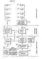
- a gas duct 1 carries hot furnace gas in a mean direction X with a velocity V g and temperature T g ⁇
- a first plane 2 perpendicular to the duct longitudinal axis and direction X
- combined units 4 of receivers 5 and transmitters 6 are located around the periphery of the duct in a first plane 2 perpendicular to the duct longitudinal axis and direction X.
- a second such plane 3 displaced from the first plane by a distance D, there are provided further combined units 4' of receivers 5' and transmitters 6'.
- Control and calculation circuitry of the measuring arrangement in accordance with the invention is shown in Figure 2, although not all receivers and transmitters are illustrated for the purposes of clarity.
- a central control unit 7 initiates in a random and discrete way the activation, from a generating unit 8, of each transmitter 5.
- the unit 8 is connected by a bus 9 to each transmitter.
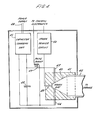
- the transmitter and its associated circuitry is shown in Figure 4 and includes a spark discharge acoustic generator.
- a horn 40 mounted in electrical insulation 41, is connected to a pipe 42 for mounting in a duct wall mounting box 30 shown in Figure 3.
- a pair of spark electrodes 43, 44 are provided facing one another.
- Electrode 44 is connected to a loud potential terminal of a charging unit 45 powered by leads 46 connected to a power supply (not shown).
- Electrode 43 is connected, via a pick up coil 47, to the high potential terminal of the unit 45.
- a rapid discharge capacitor 48 is connected across the high and low potential terminals of the charging unit 45.
- a spark can be initiated by a trigger electrode 49.
- the trigger electrode is disposed between the spark electrodes in a way such that when a potential is applied to the trigger electrode from a trigger circuit 50, the resultant distortion of the electric field between the spark electrodes produces electrical breakdown, discharge of capacitor 48 and consequent spark.
- the trigger circuit is connected by means of the bus 9 to the generating unit 8.
- the spark produced has a short duration of less than 10 microseconds and the resultant sound wave is emitted down tube 42.
- the spark electrodes have a predetermined positioning relative to one another and are located close to the apex of the horn in order to produce an optimum acoustic pulse for receipt at a receiver.
- the timing arrangement comprises a series of clocks connected by means of bus 11 to respective receivers in plane 2 and which clocks are all started by the return pulse.
- Amplifying and signal processing means 12 are provided between each clock and the receivers in order to shape the pulse produced in the receiver when an acoustic pulse is received therein.
- the receiver pulse is relayed to the timing arrangement and the pulse is shaped by the means 12 to a suitable form so that it stops the clock to which it is connected.
- control unit 7 Before each transmission occurs the control unit 7 reads out to a store means 13 the times contained in each clock in the timing arrangement and then resets the clocks to zero. Therefore when a transmitter is activated to produce an acoustic pulse the return pulse via unit 8 starts all the clocks in the timing arrangement and receipt of the acoustic pulse in a receiver produces a pulse which is shaped by the means 12 before being relayed to the timing arrangement to stop the clock to which it is connected. Therefore the contents of the array of clocks in arrangement 10 contain a measurement of the travel time of the acoustic pulse along paths from one transmitter to each receiver in the plane 2.
- each transmitter 5 is activated and the travel time of the acoustic pulse from the transmitter to each receiver 6 is measured, stored in store means 13 and subsequently read out for processing.
- the read out contents of the store means are mixed in an analyser 14, with geometry data and all required information which is contained in a store 15.
- the geometry data comprise information regarding the relative spatial geometry of the receivers and transmitters, this effectively 'being the travel path length of acoustic pulses and their relative angular relationship to one another. Consequently the analyser can evaluate the velocity of sound transmitted across the duct and evaluate a mean velocity from the number of velocity measurements made.
- a value of the tenperature along a path in plane 2 can be evaluated. These values of temperature can then be evaluated to produce a temperature in plane 2 which is a simple arithmetic mean or a weighted mean in accordance with the distance travelled.
- the transmitters and receivers in the measuring arrangement described hereinabove are arranged in a plane substantially perpendicular to the mean direction of fluid flow in a duct. In this way the velocity of the acoustic pulse is substantially unaffected by the velocity of the fluid flowing in the duct. It will be apparent that the transmitters and receivers need not be located adjacent one another and that in an enclosure wherein fluid flow is substantially negligable the arrangement of transmitters and receivers need not be in a plane. Consequently the measuring apparatus in accordance with the invention is capable of measuring the temperature of a fluid in an enclosure. By using an arrangement as described hereinabove the mean temperature can be evaluated to an accuracy of 0.5% when a total of 8 transmitter receiver positions are used. Clearly the calculations and results from the analyser 14 can be displayed or produced as hard copy on an output means 16, for example, a cathode ray tube.
- a further set of transmitters 5' and receivers 6' are provided in plane 3.
- the array of clocks in arrangement 10 are now connected to respective receivers 6 and 6'.
- the control unit 7 initiates separate activation of the transmitters 5 and 5' and the receivers 6 and 6' receive the acoustic pulses from the transmitters.
- the clock results are read out as described hereinabove and separated in analyser 14 into travel times along one path for both possible directions of travel of the acoustic pulse. By subtraction from one another of the travel times of the acoustic pulse in each direction a value is obtained bearing a direct relationship to the velocity of flow of the gas in the duct.
- the measuring arrangement can evaluate both gas velocity and gas temperature within the duct. It will be apparent that it is not essential that the transmitter and receiver pairs are contained in respective planes, this merely provides a more precise definition of location of the gas temperature and velocity measured.
- Both the temperature and velocity distribution of the fluid can be described by Fourier series with a limited number of terms.
- the coefficients of the terms can be determined provided sufficient measurements along different paths of acoustic pulses are taken to form a consistent set of equations.
- a deconvolution means 17 receives values of fluid temperature from the analyser 14 in the form of calculated coefficients of the temperature Fourier series and deconvolutes it into a temperature distribution. This temperature distribution may be either two or three-dimensional. The distribution can then be displayed by the display means 16.
- the deconvolution means 17 receives calculated coefficients of the velocity Fourier series and demodulates it into a velocity distribution between planes 2 and 3. This distribution can also be displayed by the display means.
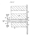
- a box 30 attached to a duct wall 31 contains heat insulating material 34 pierced by two tubular apertures 32 and 33.
- Aperture 32 receives the pipe 42 of the transmitter (not shown) and apertures 33 receives a hollow sheathed microphone tube 35 having water cooling inlet and outlet 37 and 38 respectively.
- the microphone tube 35 has a microphone 36 mounted where the tube extends from the box, exterior to the duct. Air is pumped into the hollow tube to produce a small air flow into the duct so that the temperature relationship along the tube is substantially constant for all measurements and in addition hot gas is kept out of contact with the microphone.
- the measuring arrangement in accordance with the invention allows temperature of a fluid in an enclosure to be measured by providing at least two discrete paths between at least two acoustic transmitters and receivers.
- at least three transmitters are required and a receiver is provided immediately adjacent each transmitter so that travel time of the acoustic pulse along each said path can be evaluated for both possible directions of travel.
- duct includes all manner of enclosures carrying fluids which can be flowing, for example pipes, air conduits or tubes.
Landscapes
- Physics & Mathematics (AREA)
- General Physics & Mathematics (AREA)
- Acoustics & Sound (AREA)
- Engineering & Computer Science (AREA)
- Multimedia (AREA)
- Aviation & Aerospace Engineering (AREA)
- Investigating Or Analyzing Materials By The Use Of Ultrasonic Waves (AREA)
- Measuring Temperature Or Quantity Of Heat (AREA)
Applications Claiming Priority (2)
| Application Number | Priority Date | Filing Date | Title |
|---|---|---|---|
| GB08312142A GB2139352A (en) | 1983-05-04 | 1983-05-04 | Fluid temperature and velocity measuring arrangement |
| GB8312142 | 1983-05-04 |
Publications (1)
| Publication Number | Publication Date |
|---|---|
| EP0125061A1 true EP0125061A1 (fr) | 1984-11-14 |
Family
ID=10542104
Family Applications (1)
| Application Number | Title | Priority Date | Filing Date |
|---|---|---|---|
| EP84302712A Withdrawn EP0125061A1 (fr) | 1983-05-04 | 1984-04-19 | Dispositif pour mesurer la température et la vitesse d'écoulement d'un fluide |
Country Status (2)
| Country | Link |
|---|---|
| EP (1) | EP0125061A1 (fr) |
| GB (1) | GB2139352A (fr) |
Cited By (10)
| Publication number | Priority date | Publication date | Assignee | Title |
|---|---|---|---|---|
| GB2217457A (en) * | 1988-04-05 | 1989-10-25 | Nittan Co Ltd | A multi-channel ultrasonic fire monitoring system |
| GB2235294A (en) * | 1989-08-23 | 1991-02-27 | Atomic Energy Authority Uk | Improvements in acoustic tomography |
| EP0598720A4 (en) * | 1991-08-14 | 1994-06-29 | Rockwell International Corp | Nonintrusive flow sensing system. |
| EP1887381A1 (fr) * | 2006-08-11 | 2008-02-13 | Delphi Technologies, Inc. | Procédé et dispositif destinés à la détermination de la vitesse d'un véhicule |
| EP2887036A1 (fr) * | 2013-12-18 | 2015-06-24 | Siemens Energy, Inc. | Mesure active de la température de flux de gaz, y compris dans des chambres de combustion de turbine à gaz |
| EP2985607A1 (fr) * | 2014-08-14 | 2016-02-17 | Fraunhofer Gesellschaft zur Förderung der angewandten Forschung e.V. | Anemometre et procede de determination d'une vitesse de flux |
| DE102015009121A1 (de) * | 2015-07-21 | 2017-01-26 | Bvp Gmbh | Akustische Temperaturmessung in Gasen und von Gasen |
| US9746360B2 (en) | 2014-03-13 | 2017-08-29 | Siemens Energy, Inc. | Nonintrusive performance measurement of a gas turbine engine in real time |
| US9752959B2 (en) | 2014-03-13 | 2017-09-05 | Siemens Energy, Inc. | Nonintrusive transceiver and method for characterizing temperature and velocity fields in a gas turbine combustor |
| US9945737B2 (en) | 2014-03-13 | 2018-04-17 | Siemens Energy, Inc. | Method for determining waveguide temperature for acoustic transceiver used in a gas turbine engine |
Families Citing this family (5)
| Publication number | Priority date | Publication date | Assignee | Title |
|---|---|---|---|---|
| US4630482A (en) * | 1985-06-17 | 1986-12-23 | John Traina | Method and apparatus for ultrasonic measurements of a medium |
| US4848924A (en) * | 1987-08-19 | 1989-07-18 | The Babcock & Wilcox Company | Acoustic pyrometer |
| GB9025194D0 (en) * | 1990-11-20 | 1991-01-02 | Atomic Energy Authority Uk | A method of temperature measurement & apparatus therefor |
| GB2357617A (en) | 1999-12-23 | 2001-06-27 | Mars Inc | Methods for detecting surfaces in vending machines |
| ES2280489T3 (es) | 2002-10-24 | 2007-09-16 | Mei, Inc. | Medicion de almacenamiento de monedas. |
Citations (5)
| Publication number | Priority date | Publication date | Assignee | Title |
|---|---|---|---|---|
| GB1505494A (en) * | 1975-05-22 | 1978-03-30 | Acoustic Technology Ltd | Measurement of gas temperature |
| US4162630A (en) * | 1976-09-20 | 1979-07-31 | University Of Utah | Measurement and reconstruction of three-dimensional fluid flow |
| EP0028540A1 (fr) * | 1979-11-06 | 1981-05-13 | The Electricity Council | Procédé et appareil pour une mesure acoustique sans contact des propriétés physiques de bandes métalliques continuellement en mouvement |
| US4374477A (en) * | 1980-03-25 | 1983-02-22 | Fuji Electric Co., Ltd. | Ultrasonic measuring device |
| DE3223107A1 (de) * | 1981-09-09 | 1983-03-24 | Hermann 4450 Lingen Rosen | Verfahren zur leckpruefung |
Family Cites Families (3)
| Publication number | Priority date | Publication date | Assignee | Title |
|---|---|---|---|---|
| US4145922A (en) * | 1976-12-06 | 1979-03-27 | Westinghouse Electric Corp. | Thermal power measurement apparatus |
| DE2705129C3 (de) * | 1977-02-08 | 1979-11-15 | Deutsche Texaco Ag, 2000 Hamburg | Seismisches Verfahren zur Kontrolle untertägiger Prozesse |
| DE3113522A1 (de) * | 1981-03-31 | 1982-11-04 | Siemens AG, 1000 Berlin und 8000 München | Waermemengen-messeinrichtung |
-
1983
- 1983-05-04 GB GB08312142A patent/GB2139352A/en not_active Withdrawn
-
1984
- 1984-04-19 EP EP84302712A patent/EP0125061A1/fr not_active Withdrawn
Patent Citations (5)
| Publication number | Priority date | Publication date | Assignee | Title |
|---|---|---|---|---|
| GB1505494A (en) * | 1975-05-22 | 1978-03-30 | Acoustic Technology Ltd | Measurement of gas temperature |
| US4162630A (en) * | 1976-09-20 | 1979-07-31 | University Of Utah | Measurement and reconstruction of three-dimensional fluid flow |
| EP0028540A1 (fr) * | 1979-11-06 | 1981-05-13 | The Electricity Council | Procédé et appareil pour une mesure acoustique sans contact des propriétés physiques de bandes métalliques continuellement en mouvement |
| US4374477A (en) * | 1980-03-25 | 1983-02-22 | Fuji Electric Co., Ltd. | Ultrasonic measuring device |
| DE3223107A1 (de) * | 1981-09-09 | 1983-03-24 | Hermann 4450 Lingen Rosen | Verfahren zur leckpruefung |
Cited By (14)
| Publication number | Priority date | Publication date | Assignee | Title |
|---|---|---|---|---|
| GB2217457A (en) * | 1988-04-05 | 1989-10-25 | Nittan Co Ltd | A multi-channel ultrasonic fire monitoring system |
| US4972178A (en) * | 1988-04-05 | 1990-11-20 | Nittan Company, Limited | Fire monitoring system |
| GB2217457B (en) * | 1988-04-05 | 1992-10-14 | Nittan Co Ltd | Fire monitoring system |
| GB2235294A (en) * | 1989-08-23 | 1991-02-27 | Atomic Energy Authority Uk | Improvements in acoustic tomography |
| GB2235294B (en) * | 1989-08-23 | 1993-12-22 | Atomic Energy Authority Uk | Improvements in acoustic tomography |
| EP0598720A4 (en) * | 1991-08-14 | 1994-06-29 | Rockwell International Corp | Nonintrusive flow sensing system. |
| EP1887381A1 (fr) * | 2006-08-11 | 2008-02-13 | Delphi Technologies, Inc. | Procédé et dispositif destinés à la détermination de la vitesse d'un véhicule |
| EP2887036A1 (fr) * | 2013-12-18 | 2015-06-24 | Siemens Energy, Inc. | Mesure active de la température de flux de gaz, y compris dans des chambres de combustion de turbine à gaz |
| US9709448B2 (en) | 2013-12-18 | 2017-07-18 | Siemens Energy, Inc. | Active measurement of gas flow temperature, including in gas turbine combustors |
| US9746360B2 (en) | 2014-03-13 | 2017-08-29 | Siemens Energy, Inc. | Nonintrusive performance measurement of a gas turbine engine in real time |
| US9752959B2 (en) | 2014-03-13 | 2017-09-05 | Siemens Energy, Inc. | Nonintrusive transceiver and method for characterizing temperature and velocity fields in a gas turbine combustor |
| US9945737B2 (en) | 2014-03-13 | 2018-04-17 | Siemens Energy, Inc. | Method for determining waveguide temperature for acoustic transceiver used in a gas turbine engine |
| EP2985607A1 (fr) * | 2014-08-14 | 2016-02-17 | Fraunhofer Gesellschaft zur Förderung der angewandten Forschung e.V. | Anemometre et procede de determination d'une vitesse de flux |
| DE102015009121A1 (de) * | 2015-07-21 | 2017-01-26 | Bvp Gmbh | Akustische Temperaturmessung in Gasen und von Gasen |
Also Published As
| Publication number | Publication date |
|---|---|
| GB2139352A (en) | 1984-11-07 |
| GB8312142D0 (en) | 1983-06-08 |
Similar Documents
| Publication | Publication Date | Title |
|---|---|---|
| EP0125061A1 (fr) | Dispositif pour mesurer la température et la vitesse d'écoulement d'un fluide | |
| EP0544859B1 (fr) | Systeme mesurant le temps de transfert d'une onde sonore | |
| US4586194A (en) | Earphone characteristic measuring device | |
| JP2752967B2 (ja) | 偏差測定システム | |
| CN101750516B (zh) | 一种测风仪和测量风速风向的方法 | |
| GB1483321A (en) | Acoustic method for measuring gas pressure | |
| US4676665A (en) | Distributed temperature sensor apparatus | |
| US4353256A (en) | Non-contact measurement of physical properties of continuously moving metal strip | |
| JPS58135956A (ja) | 音波による煙の監視方法 | |
| US6244114B1 (en) | Airflow measurement device | |
| Judd et al. | Transfer functions for UHF partial discharge signals in GIS | |
| US5796679A (en) | Doppler velocimeter for monitoring groundwater flow | |
| CN210075580U (zh) | 一种声矢量传感器灵敏度测量装置及系统 | |
| CN108956932A (zh) | 一种连续测量爆速装置及方法 | |
| Kidron | Measurement of the transfer function of hot-wire and hot-film turbulence transducers | |
| RU2675418C1 (ru) | Ультразвуковой акустический анемометр | |
| EP0028540A1 (fr) | Procédé et appareil pour une mesure acoustique sans contact des propriétés physiques de bandes métalliques continuellement en mouvement | |
| RU215717U1 (ru) | Акустический анемометр | |
| RU238828U1 (ru) | Ультразвуковой преобразователь накладного типа | |
| SU901895A1 (ru) | Устройство дл диагностики двухфазного потока | |
| JPS6040922A (ja) | 超音波検出器 | |
| Xu et al. | Analysis of Ultrasonic Signal Propagation of Partial Discharge in Gas Insulated Switchgear | |
| JPS62231175A (ja) | 液体流速分布測定装置 | |
| SU422958A1 (ru) | Ультразвуковой расходомер | |
| KR100189166B1 (ko) | 신규한 유량 측정장치 및 측정방법 |
Legal Events
| Date | Code | Title | Description |
|---|---|---|---|
| PUAI | Public reference made under article 153(3) epc to a published international application that has entered the european phase |
Free format text: ORIGINAL CODE: 0009012 |
|
| AK | Designated contracting states |
Designated state(s): DE FR |
|
| 17P | Request for examination filed |
Effective date: 19850607 |
|
| STAA | Information on the status of an ep patent application or granted ep patent |
Free format text: STATUS: THE APPLICATION HAS BEEN WITHDRAWN |
|
| 18W | Application withdrawn |
Withdrawal date: 19860409 |
|
| RIN1 | Information on inventor provided before grant (corrected) |
Inventor name: GREEN, STEPHEN FRANCIS |