EP0125120A2 - Appareil pour l'application de feuilles de recouvrement sur la surface de la zone des arêts ou des coins d'éléments de support - Google Patents
Appareil pour l'application de feuilles de recouvrement sur la surface de la zone des arêts ou des coins d'éléments de support Download PDFInfo
- Publication number
- EP0125120A2 EP0125120A2 EP84303026A EP84303026A EP0125120A2 EP 0125120 A2 EP0125120 A2 EP 0125120A2 EP 84303026 A EP84303026 A EP 84303026A EP 84303026 A EP84303026 A EP 84303026A EP 0125120 A2 EP0125120 A2 EP 0125120A2
- Authority
- EP
- European Patent Office
- Prior art keywords
- applicator bar
- panel
- tne
- bar
- sheet
- Prior art date
- Legal status (The legal status is an assumption and is not a legal conclusion. Google has not performed a legal analysis and makes no representation as to the accuracy of the status listed.)
- Granted
Links
- 239000000463 material Substances 0.000 title claims description 18
- 230000000712 assembly Effects 0.000 claims abstract description 20
- 238000000429 assembly Methods 0.000 claims abstract description 20
- 238000007688 edging Methods 0.000 claims description 19
- 230000001681 protective effect Effects 0.000 claims description 11
- 230000000452 restraining effect Effects 0.000 claims description 11
- 238000010438 heat treatment Methods 0.000 claims description 10
- 230000002401 inhibitory effect Effects 0.000 claims description 2
- 239000002985 plastic film Substances 0.000 abstract description 2
- 238000000034 method Methods 0.000 description 4
- 239000000853 adhesive Substances 0.000 description 3
- 230000001070 adhesive effect Effects 0.000 description 3
- 238000005452 bending Methods 0.000 description 2
- 239000011093 chipboard Substances 0.000 description 2
- 230000000694 effects Effects 0.000 description 2
- 230000003247 decreasing effect Effects 0.000 description 1
- 239000011888 foil Substances 0.000 description 1
- 239000002655 kraft paper Substances 0.000 description 1
- 239000002184 metal Substances 0.000 description 1
- 238000012986 modification Methods 0.000 description 1
- 230000004048 modification Effects 0.000 description 1
- 239000004033 plastic Substances 0.000 description 1
- 230000005855 radiation Effects 0.000 description 1
- 239000011347 resin Substances 0.000 description 1
- 229920005989 resin Polymers 0.000 description 1
- 229920001187 thermosetting polymer Polymers 0.000 description 1
- 239000002023 wood Substances 0.000 description 1
Images




Classifications
-
- B—PERFORMING OPERATIONS; TRANSPORTING
- B29—WORKING OF PLASTICS; WORKING OF SUBSTANCES IN A PLASTIC STATE IN GENERAL
- B29C—SHAPING OR JOINING OF PLASTICS; SHAPING OF MATERIAL IN A PLASTIC STATE, NOT OTHERWISE PROVIDED FOR; AFTER-TREATMENT OF THE SHAPED PRODUCTS, e.g. REPAIRING
- B29C53/00—Shaping by bending, folding, twisting, straightening or flattening; Apparatus therefor
- B29C53/02—Bending or folding
- B29C53/04—Bending or folding of plates or sheets
- B29C53/06—Forming folding lines by pressing or scoring
- B29C53/063—Forming folding lines by pressing or scoring combined with folding
-
- B—PERFORMING OPERATIONS; TRANSPORTING
- B29—WORKING OF PLASTICS; WORKING OF SUBSTANCES IN A PLASTIC STATE IN GENERAL
- B29C—SHAPING OR JOINING OF PLASTICS; SHAPING OF MATERIAL IN A PLASTIC STATE, NOT OTHERWISE PROVIDED FOR; AFTER-TREATMENT OF THE SHAPED PRODUCTS, e.g. REPAIRING
- B29C63/00—Lining or sheathing, i.e. applying preformed layers or sheathings of plastics; Apparatus therefor
- B29C63/0004—Component parts, details or accessories; Auxiliary operations
-
- B—PERFORMING OPERATIONS; TRANSPORTING
- B29—WORKING OF PLASTICS; WORKING OF SUBSTANCES IN A PLASTIC STATE IN GENERAL
- B29C—SHAPING OR JOINING OF PLASTICS; SHAPING OF MATERIAL IN A PLASTIC STATE, NOT OTHERWISE PROVIDED FOR; AFTER-TREATMENT OF THE SHAPED PRODUCTS, e.g. REPAIRING
- B29C63/00—Lining or sheathing, i.e. applying preformed layers or sheathings of plastics; Apparatus therefor
- B29C63/02—Lining or sheathing, i.e. applying preformed layers or sheathings of plastics; Apparatus therefor using sheet or web-like material
- B29C63/04—Lining or sheathing, i.e. applying preformed layers or sheathings of plastics; Apparatus therefor using sheet or web-like material by folding, winding, bending or the like
-
- B—PERFORMING OPERATIONS; TRANSPORTING
- B29—WORKING OF PLASTICS; WORKING OF SUBSTANCES IN A PLASTIC STATE IN GENERAL
- B29C—SHAPING OR JOINING OF PLASTICS; SHAPING OF MATERIAL IN A PLASTIC STATE, NOT OTHERWISE PROVIDED FOR; AFTER-TREATMENT OF THE SHAPED PRODUCTS, e.g. REPAIRING
- B29C37/00—Component parts, details, accessories or auxiliary operations, not covered by group B29C33/00 or B29C35/00
- B29C37/0053—Moulding articles characterised by the shape of the surface, e.g. ribs, high polish
- B29C37/0057—Moulding single grooves or ribs, e.g. tear lines
Definitions
- THIS INVENTION relates to the application of surfacing sheets to support members such as panels, columns and the like and, more particularly, but not exclusively, to panels of the nature of a door or a desk top.
- heat activated adhesives are often pre-applied to the surfacing sheet so that they can be secured to the substrata with the aid of heat and pressure. In some other cases heat is not even necessary.
- apparatus for applying sheet material around an edge or corner of a carrier member, said apparatus comprising a frame, a support arrangement for the carrier member for supporting it in a roughly predetermined position, an applicator bar associated with the frame and extending along the required length of the support arrangement, means for urging the applicator bar towards the surface of a carrier member supported in the apparatus, means for causing simultaneous lateral movement of the applicator bar relative to said surface whilst in contact therewith;; and lateral restraining means for inhibiting uncontrolled or undesired lateral movement of the applicator bar.
- tne applicator bar to be flat and to embody heating means for selectively heating the bar when required; for the applicator bar and lateral restraining means associated therewith to be carried on rotatable end supports rotatable in unison and supporting therebetween frame members for mounting the urging means and lateral restraining means for the applicator bar; for the support arrangement to.
- the apparatus to include a jig member for locating an edging strip relative to a panel so that a surfacing sheet is adhered to tne major surface of both the panel and the edging strip prior to tne sheet being rotated around radiused edges to the panel and the edging strip with the surfacing sheet being simultaneously and automatically adhesively secured to the radiused edges of the panel itself and that of the edging strip.
- a pair of rotatable end supports carry between them a pair of laterally spaced parallel primary frame members witn a plurality of spaced urging means carried by one of such primary frame members.
- Tne urging means preferably assume the form of pneumatic or hydraulic piston and cylinder assemblies. Tne axes of such piston and cylinder assemblies are preferably at roughly right angles to the plane in which the applicator bar is to operate and the lateral restraining means, which may be in the form of pivotally mounted arms or plates, may be hinged to the other frame member.
- the urging means can act directly on the applicator bar or on the arms or plates forming the lateral restraining means.
- the arms or plates defining the lateral restraining means are at roughtly right angles to the axes of the piston and cylinder assemblies (ie parallel to the surface of the carrier member being engaged at any time by the applicator bar).
- the applicator bar is hingedly connected to the member carrying same to provide for limited free movement so that it can assume an operative position according to its contact with a surface.
- the surfacing sheet can be susceptible to damage of any sort as a result of lateral sliding of the applicator bar thereon, an interposed protective, but usually heat conductive sheet, may be interposed between the applicator bar and the surfacing sheet. Sheets such as veneers may require this type of protection.
- the motion of the applicator bar provided by apparatus of this invention relative to the surfacing sheet is one in which the applicator bar tends to pull and smootn the surfacing sheet in a taught condition onto the surface with a sliding motion.
- the edges or carrier being surfaced may be sharp (e.g. where veneer is employed as the surface sheet) but generally it will be radiused.
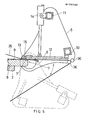
- the apparatus comprises a support frame, generally indicated by numeral 1, which supports a table 2 and co-operating clamp assembly 3 for clamping panels or doors to the table.
- Tne clamp assembly is preferably operated D y a plurality of spaced pneumatic or hydraulic piston and cylinder assemblies 4.
- a pair of end supports 5 are rotatable about an axis 6 wnich is located, in operation, in the vicinity of the corner 7 of a projecting end of a panel 8 to be covered with a sheet material 9.
- the edge of the panel is radiused, as indicated above, but by using the apparatus of tnis invention, the radius of curvature can be as little as 8mm for the sheet material employed as a cover and which is the same as has been used heretofore with a minimum radius of curvature of 16mm.
- the advantage here is attained by the fact that contact heat is employed and the heat is applied to the region of the sheet where it is necessary in order to achieve a bending thereof.
- the sheet was initially heated using infra red radiation which was removed prior to the bending operation taking place. This provided time for it to cool appreciably as described.
- the end supports carry between them a pair of longitudinally extending beams 10 and 11 the one of which is angularly offset from the other relative to the axis of rotation of the end supports.
- the one support beam 10 nas pivotally attached thereto an arm arrangement 12 which is conveniently in the form of a continuous metal plate and wnich extends inwardly towards a region in which the projecting edge of a panel will be in use.
- This assembly carries at its free end a hingedly mounted, substantially flat applicator bar 13 extending along the length of the apparatus.
- a row of pneumatic piston and cylinders 14 is mounted to the other support beam 11 which is orientated such that tne pneumatic piston and cylinder assemblies can be employed for urging the free ends of the arm arrangement,and thus the applicator bar 13, towards a projecting end of a panel or the like clamped to the table in use.
- the applicator bar is, in this embodiment of the invention, provided with a resistance heating element 15 therein so that its temperature can be controlled to a temperature at which the surfacing sheets are not damaged but are, nevertheless, rendered sufficiently pliable to bend them around a radiused end of a panel or door.
- a resistance heating element 15 therein so that its temperature can be controlled to a temperature at which the surfacing sheets are not damaged but are, nevertheless, rendered sufficiently pliable to bend them around a radiused end of a panel or door.
- the contact heat is highly desirable and provides extremely advantageous results.
- the apparatus illustrated in Figs. 1 to 3 and 4 and 5 are substantially identical but, in the embodiment of Figs. 4 and 5, the table 2 is mounted to the upper end of a pair of supporting piston and cylinder assemblies 16 which can be either hydraulic or pneumatic as may be required.
- the table 2 may be adjusted in heignt and the clamp 3 operates against the piston and cylinder assemblies 16.
- the whole clamp arrangement and panel 8 can be moved upwardly and downwardly relative to tne applicator bar 13.
- This arrangement has a tremendous advantage where extremely thick panels or other arrangements having a high front face are to be surfaced using the sheet materials under consideration.
- a panel such as a chip board door, for example, is firstly provided with radiused edges by means of suitable cutters in known manner.
- a sheet of surfacing material as well as at least the outer major face thereof.
- thermosetting resin surfacing material In order to form a door of this nature a sheet of known incompletely cured thermosetting resin surfacing material is bonded to the major surface of the door and the surfacing sheet is allowed to project beyond the edge 7 of the door.
- the above arrangement would be such that the surfacing sheet would be uppermost and, in such a case, the end supports for the applicator bar assembly are located in a position in whicn tne applicator bar can be engaged properly with such upper surface immediately adjacent the radiused edge of the door or panel
- Tne pneumatic cylinders 14 associated with the applicator bar are activated and the applicator bar is thereby urged against the surfacing sheet to move it into intimate contact witn the surface of the door.
- the arm arrangement is sufficiently flexible to twist or bend to accommodate misalignment or other non-conformities.
- the applicator bar moves away from the major portion of the door or panel itself it will be drawn, whilst engaging the surfacing sheet around the edge, thereby tending to stretch the sneet somewhat towards the projecting edge thereof.
- the applicator bar reaches the radiused edge it will continue to urge, by reason of the presence of the pneumatic piston and cylinder assemblies, the surfacing sheet into intimate contact with the radiused edge of the door or panel. Being hingedly mounted, the applicator bar will assume a postion in which it contacts the longest surface area in the region being treated.
- the resistance heating element in the applicator bar will be activated during the above described process.
- the process is thus carried out at a speed sufficiently slow to enable adequate neat transfer from the applicator bar to the surfacing sheet material to take place without the sheet material being overheated but, with the sneet material being heated to an optimum extent.
- a smaller radius of curvature can be achieved in the bend of the surfacing sheet around a radiused edge of a door or panel as well as a full 180 degree bend arrangement can be produced to fold the surfacing sheet completely around a projecting radiused endge of a door.
- the arm arrangement which is located basically on the side of the pneumatic piston and cylinders opposite the door edge, prevents unwanted lateral movement of the applicator bar.
- the movement of the applicator bar 13 may be controlled further.
- the bar adjacent each of the edges, the bar can be held stationery relative to the surfacing sheet to ensure that proper adhesion is acnieved in the regions immediately adjacent a radiused part thereof.
- the applicator bar can tnen be moved around the radiused edge and again held stationary relative to a vertical front face 17 of a thick panel (see Fig. 4) or the like again immediately adjacent the radiused corner. This ensures that the surfacing sheet is properly adhered to the panel or the like immediately adjacent the radiused corners.
- tne table 2 can be moved upwardly so tnat , the surfacing sheet is applied to the rather high front face of the panel and, when the applicator bar is adjacent tne lowermost radiused edge, the table may be stopped and the end supports 5 can be further rotated to cause the applicator to apply the surfacing sheet to a lower radiused corner.
- the applicator D ar can be stopped for a predetermined period of time at both sides of the radiused edge to ensure proper adhesion.
- Tne apparatus has a nignly desirable effect in that the surfacing sheet is almost stretcned onto the surface of the panel or the like so that no regions of the surfacing sneet remain out of contact with the surface to wnicn it is bonded.
- the device is substantially tne same apart from the introduction of a jig member 18 which is shaped to co-operate with a rebated end 19 of a door or desk top panel 20 or tne like.
- An edging strip 21 is located by the jig member 18 in proper spaced relationship relative to. the panel 20 and a surfacing sheet 22 which has been applied to the surface of the panel projects over tne edging strip 21.
- the edging strip also has a rebated edge 23 so that, when it is rotated about 90°, it will co-operate properly with the rebated end of the panel. Tne final position of the edging strip 21 and panel 20 is illustrated in Fig. 7.
- Tne outer surfaces of the rebated end and the lower edge 24 of the edging strip are radiused and, after tne surfacing sheet 22 nas been secured to the edging strip, the jig member 18 can be swung out of the way, it being suitably mounted to do this.
- the apparatus described above with reference to Figs. 1 to 5 can then be used in the normal way and the applicator bar will initially engage the surfacing sheet 22 where it is bonded to the surface of the door panel adjacent its radiused edge 25.
- the jig member defines a space 26 of the surfacing sheet between the edging strip and the panel so that this region can become bonded to the radiused edge 25 of the door panel.
- the applicator bar engages the edge of the panel and, if it is not too wide, extends over the surfacing sheet between the panel and over tne part of the surfacing sheet covering the edging strip.
- the applicator bar remains in this position for long enough to effect the required heating and bonding of the surfacing sheet to the edging strip and then starts to move laterally around the radiused edge of the door.
- the edging strip which has been released in consequence of the jig moving to an inoperative position, moves into its proper position in which the rebates 19 and 23 co-operate.
- Suitable adhesive is used, or preapplied to tne co-operating surfaces of tne rebates so that the edging strip becomes bonded into its final position as illustrated in Fig. 7.
- Tne applicator bar moves to permanently bond the surfacing sheet to any rather enlarged vertical surface of the edge of tne panel where tne edging strip was too wide to be covered by tne applicator bar initially, and thereafter around the lower radiused edge 19 of the edging strip.
- the vertically movable table 2 can be employed if the height of the edging strip is sufficiently great to warrant it.
- Otnerwise tne table can be neld stationary wnilst tne applicator bar heats and applies the surfacing sheet.
- tne end supports need not necessarily be employed or, alternatively, if they are present tney could be neld stationary and the column rotated by an arrangement as illustrated in Figs. 8 and 9.
- tne apparatus can comprise a pair of rotatable mounting assemblies 27 supported on tne main support 2 of apparatus according to this invention and the mounting assemblies can be axially retractable so as to grip a column 29 end-on tnerebetween.
- the applicator bar 30 is again urged towards the surface of a column 29 held by the rotatable mounting assemblies 27 and the end supports 31 can be held stationary or, alternatively, can be fixed relative to tne frame 28 of the apparatus.
- Similar pneumatic piston and cylinder assemblies 32 are employed for urging the applicator bar 30 towards tne surface of tne column 29 and lateral restraining arms 33 are again provided, conveniently in the form of a plate as outlined above.
- the end supports 31 could be made movable in a direction towards and away from the axis 34 of rotation of the rotatable mounting assemblies 27 or, alternatively, tne axis of tne mounting assemblies could be made movable relative to the end supports. In either event the size ranges wnicn can be accommodated by the apparatus is determined by this type of adjustment or movement.
- the surfacing sheet is of a nature sucn tnat it is susceptible to damage by the sliding action of the applicator bar thereon a protective sheet can be employed to be located between the surfacing sheet and applicator bar.
- a roll of a protective sheet material indicated by numeral 35 may De provided on the side of the clamp 3 remote from tne end supports, and as shown in Figs. 4 and 5, a roll of a protective sheet material indicated by numeral 35 may De provided on the side of the clamp 3 remote from tne end supports, and as shown in Figs. 4 and 5, a roll of a protective sheet material indicated by numeral 35 may De provided.
- Tne sheet material is sucn that it can be drawn under the clamp 3 so as to be positioned between the clamp and a surfacing sneet 9 being applied.
- Tne protective sneet 35 is passed between a pair of rollers 36 carried by the end supports and extending parallel to the longitudinally extending beams 10 and 11 to wnicn the arm arrangement 12 is mounted. Witn this arrangement tne protective sneet 35 extends rougnly parallel to the arm arrangement. Tne protective sneet, whicn extends from between tne rollers 36, is preferably attached to a take-up roller 37 carried by the frame and located beneatn the table 2. Alternatively a weight 38 (shown in dotted lines) could be attached to the free end and the weight could be moved along the length of the protective sheet as and when required.
- the protective sheet which may be Kraft paper, plastic foil or the like
- the surface of the surfacing sheet will not be damaged in any way as a result of the applicator bar being drawn laterally across the sheet while being urged towards it.
- the protective sheet must be sufficiently heat conductive where the applicator bar is of the heated type so as to avoid unnecessary heat losses or inadequate heating of adhesive.
- the applicator bar, wnich is in these embodiments of the invention a flat bar, could be replaced by a bar having a right-angled section so that, as the material is folded about the radiused corner of a panel, the two surfaces joined by tne corner can be pressed into engagement with the surfaces of the door or panel simultaneously for a short while. This may not be necessary in most cases.
- the exact arrangement whereby the applicator bar is mounted to the apparatus can be varied widely and the arrangement described above could be varied in many ways involving only structural changes, but none in principle.
- the rather multitudinous pneumatic piston and cylinder assemblies could be decreased in number or replaced with mechanical or other forms of urging or biasing the applicator bar such as a leaf spring arrangement, for example.
Landscapes
- Engineering & Computer Science (AREA)
- Manufacturing & Machinery (AREA)
- Mechanical Engineering (AREA)
- Coating Apparatus (AREA)
- Lining Or Joining Of Plastics Or The Like (AREA)
- Laminated Bodies (AREA)
- Shaping Of Tube Ends By Bending Or Straightening (AREA)
Priority Applications (1)
| Application Number | Priority Date | Filing Date | Title |
|---|---|---|---|
| AT84303026T ATE46655T1 (de) | 1983-05-09 | 1984-05-04 | Vorrichtung zum aufbringen von deckfolienmaterial auf flaechen im bereich von kanten oder ecken von traegerelementen. |
Applications Claiming Priority (6)
| Application Number | Priority Date | Filing Date | Title |
|---|---|---|---|
| ZA833280 | 1983-05-09 | ||
| ZA833280 | 1983-05-09 | ||
| ZA834929 | 1983-07-06 | ||
| ZA834929 | 1983-07-06 | ||
| ZA836887 | 1983-09-16 | ||
| ZA836887 | 1983-09-16 |
Publications (3)
| Publication Number | Publication Date |
|---|---|
| EP0125120A2 true EP0125120A2 (fr) | 1984-11-14 |
| EP0125120A3 EP0125120A3 (en) | 1986-11-05 |
| EP0125120B1 EP0125120B1 (fr) | 1989-09-27 |
Family
ID=27420915
Family Applications (1)
| Application Number | Title | Priority Date | Filing Date |
|---|---|---|---|
| EP84303026A Expired EP0125120B1 (fr) | 1983-05-09 | 1984-05-04 | Appareil pour l'application de feuilles de recouvrement sur la surface de la zone des arêts ou des coins d'éléments de support |
Country Status (6)
| Country | Link |
|---|---|
| EP (1) | EP0125120B1 (fr) |
| AU (1) | AU2778384A (fr) |
| CA (1) | CA1227732A (fr) |
| DE (1) | DE3479875D1 (fr) |
| ES (1) | ES8505857A1 (fr) |
| IL (1) | IL71767A (fr) |
Cited By (4)
| Publication number | Priority date | Publication date | Assignee | Title |
|---|---|---|---|---|
| EP0186143A3 (fr) * | 1984-12-28 | 1987-04-15 | HEINRICH BRANDT MASCHINENBAU GmbH | Appareil pour appliquer des feuilles de revêtement sur des éléments en forme de plaques ou analogues |
| FR2595622A1 (fr) * | 1986-03-14 | 1987-09-18 | Billaud Robert | Machine de postformage entierement automatique permettant de postformer les stratifies postformables et toutes les matieres thermoplastiques |
| EP0422459A3 (en) * | 1989-10-12 | 1991-11-06 | Davidson Textron Inc. | Method and apparatus for forming a door panel belt trim |
| DE4308925A1 (de) * | 1993-03-19 | 1995-02-23 | Wmt Gmbh Werkzeug & Maschinenb | Verfahren und Vorrichtungen zum Umlegen und Befestigen des am Teilrand überstehenden Bezugsmaterials, insbesondere für Fahrzeuginnenverkleidungsteile |
Families Citing this family (1)
| Publication number | Priority date | Publication date | Assignee | Title |
|---|---|---|---|---|
| ES2329101B2 (es) * | 2006-08-01 | 2010-03-26 | Codifel, S.L. | Procedimiento para la proteccion de cantos de tableros. |
Family Cites Families (13)
| Publication number | Priority date | Publication date | Assignee | Title |
|---|---|---|---|---|
| US2542860A (en) * | 1946-01-19 | 1951-02-20 | Clements Macmillan | Edge construction |
| US2739637A (en) * | 1954-02-08 | 1956-03-27 | North American Aviation Inc | Method and device for bending c-stage postformable plastic material |
| US3028275A (en) * | 1957-01-08 | 1962-04-03 | Earl R Peterson | Post forming press |
| US2937689A (en) * | 1957-02-08 | 1960-05-24 | Uniflex Engineering Inc | Material bending apparatus |
| FR1220275A (fr) * | 1958-11-11 | 1960-05-24 | Elleci | Procédé pour courber des stratifiés de matière plastique et machine pour la miseen oeuvre de ce procédé |
| US3009201A (en) * | 1959-10-29 | 1961-11-21 | Fawn Fabricators Inc | Material bending machine with roll bar |
| GB1013942A (en) * | 1961-10-17 | 1965-12-22 | W H Foster & Sons Ltd | Methods of and apparatus for forming bends in sheet material |
| DE1252578B (de) * | 1964-03-30 | 1967-10-19 | Midland Ross Corporation, Cleve land, Ohio (V St A) | Behalter wie Gehäuse mit mehrschichtiger Wandung |
| GB1146147A (en) * | 1965-11-30 | 1969-03-19 | Ralph M Evans | Laminating method and apparatus |
| DE2430016B2 (de) * | 1974-06-22 | 1979-06-13 | Blaupunkt-Werke Gmbh, 3200 Hildesheim | Verfahren zur Herstellung von Radio- oder Fernsehgerätegehäusen |
| DE2528292A1 (de) * | 1975-06-25 | 1977-01-13 | Westag & Getalit Ag | Maschine und verfahren zum verleimen einer kunststoffplatte mit einer traegerplatte |
| US4035224A (en) * | 1976-04-08 | 1977-07-12 | The Shaw-Walker Company | Method and apparatus for forming a top assembly |
| US4334947A (en) * | 1980-10-16 | 1982-06-15 | Zaino Richard J | Press apparatus |
-
1984
- 1984-04-30 CA CA000453155A patent/CA1227732A/fr not_active Expired
- 1984-05-04 DE DE8484303026T patent/DE3479875D1/de not_active Expired
- 1984-05-04 ES ES84532226A patent/ES8505857A1/es not_active Expired
- 1984-05-04 EP EP84303026A patent/EP0125120B1/fr not_active Expired
- 1984-05-04 IL IL71767A patent/IL71767A/xx unknown
- 1984-05-08 AU AU27783/84A patent/AU2778384A/en not_active Abandoned
Cited By (4)
| Publication number | Priority date | Publication date | Assignee | Title |
|---|---|---|---|---|
| EP0186143A3 (fr) * | 1984-12-28 | 1987-04-15 | HEINRICH BRANDT MASCHINENBAU GmbH | Appareil pour appliquer des feuilles de revêtement sur des éléments en forme de plaques ou analogues |
| FR2595622A1 (fr) * | 1986-03-14 | 1987-09-18 | Billaud Robert | Machine de postformage entierement automatique permettant de postformer les stratifies postformables et toutes les matieres thermoplastiques |
| EP0422459A3 (en) * | 1989-10-12 | 1991-11-06 | Davidson Textron Inc. | Method and apparatus for forming a door panel belt trim |
| DE4308925A1 (de) * | 1993-03-19 | 1995-02-23 | Wmt Gmbh Werkzeug & Maschinenb | Verfahren und Vorrichtungen zum Umlegen und Befestigen des am Teilrand überstehenden Bezugsmaterials, insbesondere für Fahrzeuginnenverkleidungsteile |
Also Published As
| Publication number | Publication date |
|---|---|
| IL71767A (en) | 1987-08-31 |
| EP0125120A3 (en) | 1986-11-05 |
| CA1227732A (fr) | 1987-10-06 |
| EP0125120B1 (fr) | 1989-09-27 |
| AU2778384A (en) | 1984-11-15 |
| IL71767A0 (en) | 1984-09-30 |
| ES532226A0 (es) | 1985-06-16 |
| ES8505857A1 (es) | 1985-06-16 |
| DE3479875D1 (en) | 1989-11-02 |
Similar Documents
| Publication | Publication Date | Title |
|---|---|---|
| US4035224A (en) | Method and apparatus for forming a top assembly | |
| CN111319337B (zh) | 一种装饰板材及其生产线、生产工艺 | |
| US3717366A (en) | Method and apparatus used for book binding | |
| US5871323A (en) | Bookbinding | |
| US4563233A (en) | Application of surfacing sheet to panels, columns and the like | |
| US4539065A (en) | Application of surfacing sheets to support members therefor | |
| EP0125120A2 (fr) | Appareil pour l'application de feuilles de recouvrement sur la surface de la zone des arêts ou des coins d'éléments de support | |
| US4671500A (en) | Double acting clamp | |
| US20010045259A1 (en) | System for applying a wood veneer across a corner of an elongate core | |
| US4539066A (en) | Application of surfacing sheets to panels, columns and the like | |
| US5417788A (en) | Method and installation for producing a panel | |
| CN100493923C (zh) | 热粘合的方法 | |
| EP0737119B1 (fr) | Appareil de reglage d'un dispositif de positionnement pour le soudage de toles | |
| USRE28758E (en) | Method and apparatus used for book binding | |
| US4741797A (en) | Apparatus for applying surfacing sheets to support surfaces therefor | |
| US5635280A (en) | Postforming method and apparatus | |
| US4193830A (en) | Method of surface laminating | |
| CN216511494U (zh) | 应用于书本印刷工序的物料翻转辅助装置 | |
| CN220576809U (zh) | 一种汽车玻璃夹胶合片加热设备 | |
| KR200301552Y1 (ko) | 에지밴딩 및 열전사장치 | |
| US4704182A (en) | Press for applying an overlay | |
| CN220464800U (zh) | 一种高精度覆膜机 | |
| US6129655A (en) | Method of folding and shaping sheet, and apparatus for folding and shaping sheet | |
| CA1263077C (fr) | Dispositif d'entrecollage de materiau en feuilles | |
| JPH02179745A (ja) | 化粧板製造装置 |
Legal Events
| Date | Code | Title | Description |
|---|---|---|---|
| PUAI | Public reference made under article 153(3) epc to a published international application that has entered the european phase |
Free format text: ORIGINAL CODE: 0009012 |
|
| AK | Designated contracting states |
Designated state(s): AT BE CH DE FR GB IT LI LU NL SE |
|
| 17P | Request for examination filed |
Effective date: 19851014 |
|
| RAP1 | Party data changed (applicant data changed or rights of an application transferred) |
Owner name: HEINRICH BRANDT MASCHINENBAU GMBH |
|
| RIN1 | Information on inventor provided before grant (corrected) |
Inventor name: SCHMITT, K. H. Inventor name: HENDERSON, P. M. |
|
| ITCL | It: translation for ep claims filed |
Representative=s name: BARZANO' E ZANARDO MILANO S.P.A. |
|
| PUAL | Search report despatched |
Free format text: ORIGINAL CODE: 0009013 |
|
| AK | Designated contracting states |
Kind code of ref document: A3 Designated state(s): AT BE CH DE FR GB IT LI LU NL SE |
|
| 17Q | First examination report despatched |
Effective date: 19870918 |
|
| GRAA | (expected) grant |
Free format text: ORIGINAL CODE: 0009210 |
|
| AK | Designated contracting states |
Kind code of ref document: B1 Designated state(s): AT BE CH DE FR GB IT LI LU NL SE |
|
| REF | Corresponds to: |
Ref document number: 46655 Country of ref document: AT Date of ref document: 19891015 Kind code of ref document: T |
|
| ITF | It: translation for a ep patent filed | ||
| REF | Corresponds to: |
Ref document number: 3479875 Country of ref document: DE Date of ref document: 19891102 |
|
| ET | Fr: translation filed | ||
| PLBE | No opposition filed within time limit |
Free format text: ORIGINAL CODE: 0009261 |
|
| STAA | Information on the status of an ep patent application or granted ep patent |
Free format text: STATUS: NO OPPOSITION FILED WITHIN TIME LIMIT |
|
| 26N | No opposition filed | ||
| ITTA | It: last paid annual fee | ||
| EPTA | Lu: last paid annual fee | ||
| EAL | Se: european patent in force in sweden |
Ref document number: 84303026.3 |
|
| PGFP | Annual fee paid to national office [announced via postgrant information from national office to epo] |
Ref country code: LU Payment date: 19950401 Year of fee payment: 12 |
|
| PGFP | Annual fee paid to national office [announced via postgrant information from national office to epo] |
Ref country code: FR Payment date: 19950407 Year of fee payment: 12 |
|
| PGFP | Annual fee paid to national office [announced via postgrant information from national office to epo] |
Ref country code: SE Payment date: 19950410 Year of fee payment: 12 |
|
| PGFP | Annual fee paid to national office [announced via postgrant information from national office to epo] |
Ref country code: CH Payment date: 19950411 Year of fee payment: 12 |
|
| PGFP | Annual fee paid to national office [announced via postgrant information from national office to epo] |
Ref country code: GB Payment date: 19950505 Year of fee payment: 12 |
|
| PGFP | Annual fee paid to national office [announced via postgrant information from national office to epo] |
Ref country code: BE Payment date: 19950510 Year of fee payment: 12 |
|
| PGFP | Annual fee paid to national office [announced via postgrant information from national office to epo] |
Ref country code: AT Payment date: 19950529 Year of fee payment: 12 |
|
| PGFP | Annual fee paid to national office [announced via postgrant information from national office to epo] |
Ref country code: NL Payment date: 19950531 Year of fee payment: 12 |
|
| PG25 | Lapsed in a contracting state [announced via postgrant information from national office to epo] |
Ref country code: LU Free format text: LAPSE BECAUSE OF NON-PAYMENT OF DUE FEES Effective date: 19960504 Ref country code: GB Effective date: 19960504 Ref country code: AT Effective date: 19960504 |
|
| PG25 | Lapsed in a contracting state [announced via postgrant information from national office to epo] |
Ref country code: SE Effective date: 19960505 |
|
| PG25 | Lapsed in a contracting state [announced via postgrant information from national office to epo] |
Ref country code: LI Effective date: 19960531 Ref country code: CH Effective date: 19960531 Ref country code: BE Effective date: 19960531 |
|
| BERE | Be: lapsed |
Owner name: HEINRICH BRANDT MASCHINENBAU G.M.B.H. Effective date: 19960531 |
|
| PG25 | Lapsed in a contracting state [announced via postgrant information from national office to epo] |
Ref country code: NL Effective date: 19961201 |
|
| GBPC | Gb: european patent ceased through non-payment of renewal fee |
Effective date: 19960504 |
|
| REG | Reference to a national code |
Ref country code: CH Ref legal event code: PL |
|
| PG25 | Lapsed in a contracting state [announced via postgrant information from national office to epo] |
Ref country code: FR Effective date: 19970131 |
|
| EUG | Se: european patent has lapsed |
Ref document number: 84303026.3 |
|
| NLV4 | Nl: lapsed or anulled due to non-payment of the annual fee |
Effective date: 19961201 |
|
| REG | Reference to a national code |
Ref country code: FR Ref legal event code: ST |
|
| PGFP | Annual fee paid to national office [announced via postgrant information from national office to epo] |
Ref country code: DE Payment date: 19970612 Year of fee payment: 14 |
|
| PG25 | Lapsed in a contracting state [announced via postgrant information from national office to epo] |
Ref country code: DE Free format text: LAPSE BECAUSE OF NON-PAYMENT OF DUE FEES Effective date: 19990302 |