EP0125326A1 - Kernreaktor - Google Patents
Kernreaktor Download PDFInfo
- Publication number
- EP0125326A1 EP0125326A1 EP83104721A EP83104721A EP0125326A1 EP 0125326 A1 EP0125326 A1 EP 0125326A1 EP 83104721 A EP83104721 A EP 83104721A EP 83104721 A EP83104721 A EP 83104721A EP 0125326 A1 EP0125326 A1 EP 0125326A1
- Authority
- EP
- European Patent Office
- Prior art keywords
- calandria
- core
- vessel
- reactor
- coolant
- Prior art date
- Legal status (The legal status is an assumption and is not a legal conclusion. Google has not performed a legal analysis and makes no representation as to the accuracy of the status listed.)
- Granted
Links
Images


Classifications
-
- G—PHYSICS
- G21—NUCLEAR PHYSICS; NUCLEAR ENGINEERING
- G21C—NUCLEAR REACTORS
- G21C1/00—Reactor types
- G21C1/04—Thermal reactors ; Epithermal reactors
- G21C1/06—Heterogeneous reactors, i.e. in which fuel and moderator are separated
- G21C1/08—Heterogeneous reactors, i.e. in which fuel and moderator are separated moderator being highly pressurised, e.g. boiling water reactor, integral super-heat reactor, pressurised water reactor
-
- Y—GENERAL TAGGING OF NEW TECHNOLOGICAL DEVELOPMENTS; GENERAL TAGGING OF CROSS-SECTIONAL TECHNOLOGIES SPANNING OVER SEVERAL SECTIONS OF THE IPC; TECHNICAL SUBJECTS COVERED BY FORMER USPC CROSS-REFERENCE ART COLLECTIONS [XRACs] AND DIGESTS
- Y02—TECHNOLOGIES OR APPLICATIONS FOR MITIGATION OR ADAPTATION AGAINST CLIMATE CHANGE
- Y02E—REDUCTION OF GREENHOUSE GAS [GHG] EMISSIONS, RELATED TO ENERGY GENERATION, TRANSMISSION OR DISTRIBUTION
- Y02E30/00—Energy generation of nuclear origin
- Y02E30/30—Nuclear fission reactors
Definitions
- This invention relates to nuclear reactors and has particular relationship to reactors in which a coolant, typically water at critical temperature and pressure, is circulated through the nuclear core disposed in a reactor vessel.
- the core includes the fuel and is arranged in the lower region of the reactor vessel.
- the reactor includes control-rod assemblies.
- Control-rod assemblies include control rods, supports for the control rods, drive rods for a number of control rods and other related components.
- the core with its fuel assemblies is usually referred to as the lower internals of the reactor.
- the control rods and rod guides are referred to as the upper internals of the reactor.
- the control rods are movable between the upper internals and recesses or thimbles in the core by the drive rods.
- the control rods are mounted in clusters on their drive rods by means of spiders.
- rod clusters (RCC's) in which the rods have a high absorption cross-section for neutrons. These clusters are used to reduce the power or shut down the reactor and are moved between the core and their guides a number of times during the fuel cycle of a reactor.
- gray control rods of substantially lower neutron absorption cross-section than the high-absorption RCC's and they serve for load follow or to moderate or control the power of the reactor.
- Gray rods are moved between the core and the guides many times (typically 5,600), substantially more than the high-absorption RCC's, during the fuel cycle of a reactor.
- WDRC's water displacement clusters
- These rods are of the same diameter as the RCC's. They are used to maintain the amount of water coolant in the core relatively high during early operation of the reactor and to permit the amount of the water coolant in the core to increase during the later operation of the reactor by removal of the displacement rods.
- Such water displacement rod clusters are in the core typically during the first 60% of a fuel cycle, and are raised into the upper internals during the rema nder, typically 40% of the fuel cycle.
- the RCC's and the gray rods in their clusters are carried by cruciform supports and are movable inside of hollow cruciform guides. These guides conventionally have slots through which coolant flows.
- the WDRC's are not so protected.A large number of these tubes are movable in rectangular or square guides which conventionally have holes through which the coolant flows. During the later part of the iuel cycle, the WDRC's are moved into and remain in perforated guides. All guides are part of the upper internals of the reactor.
- the coolant flows vertically through the core and into the upper internals.
- the outlet nozzles of the vessel are disposed between she ends of the upper internals and they cause the coolait to flow horizontally.
- the coolant then flows generally transversely through the control-rod assemblies i. passing to the nozzles.
- the vertical flow of the coolant through the core has a velocity of aboit 5 m/sec.
- the flow through the nozzles has a velocity of about 15 m/sec and the crossflow through some regions f the upper internals may be as high as 9 to 12 m/sec.
- the coolant causes the vertical membe 5and particularly the WDRC's, during the later part of the fuel cycle, to vibrate.
- the mechanisms which cause the vibrations include vortex shedding, turbulent buffeting, fluid-elastic interaction, and cavitation.
- a nuclear reactor including a vessel, a nuclear core supported within said vessel, control-rod assemblies movably supported within said vessel and guided by vertical control-rod guide means arranged in a plenum above said core, and drive rods connected to said control-rod assemblies for moving said control rods into, and out of, said core, said vessel having at least one inlet nozzle for supplying a coolant to said core, the inflowing coolant after passing upwardly through said core flowing past said guide means to an outlet nozzle disposed in the side wall of said vessel, characterized in that a calandria extends across said vessel above said core sufficiently spaced therefrom that a yoke member carrying a plurality of control rods is movable in the space between said calandria and the core and that said calandria includes a plurality of hollow members, receiving said drive rods and mounted between an upper support plate and a lower support structure, said lower support structure being perforate for the coolant flowing axially upward
- a nuclear reactor 11 includes a pressure vessel having a circularly cylindrical body 15 closed at the bottom by a spherical bowl 17.
- the vessel has a flanged dome-shaped head 19 which is bolted to the body at the flange 21.
- the body 15 has a plurality of inlet nozzles 23 and a plurality of outlet nozzles 25 distributed around its periphery. Typically, there are four inlet nozzles 23 interspaced in pairs between four outlet nozzles 25.
- a nuclear core 27 In the lower region of body 15 there is a nuclear core 27.
- This core includes fuel assemblies 29 and thimbles 31 for receiving control rods (not shown).
- the fuel assemblies 29 and thimbles 31 are mounted between upper core plate 33 and lower core plate 35.
- the control rods are mounted in clusters by means of a yoke member and include rod clusters (RCC's), which have a high absorption cross-section for neutrons, gray rod clusters, which have a lower absorption cross-section for neutrons, and water- displacement rod clusters (WDRC's).
- the RCC's serve to shut down the reactor or to reduce its thermal power output.
- the gray clusters serve for load follow control.
- the WDRC's displace the coolant in thimbles which do not receive RCC's or gray rod clusters. Such displacement takes place during the earlier part of the fuel cycle of the reactor, typically during about the first 60% of the fuel cycle.
- the upper part of the body 15 contains the upper internals 37 and the calandria 39.
- the upper internals 37 include the vertical guides 41 (Fig. 3) for the RCC's and gray control-rod clusters, and the vertical guides 43 for the WDRC's.
- the RCC's and gray control-rod clusters are mounted on cruciform structures 40 and the guides 41 for these rods are hollow cruciform cans.
- the guides 43 for the WDRC's are of generally rectangular or square cross-section with their corners truncated, and strictly may be described as octagonal cans.
- the sides 38 of the WDRC guides 43 are encompassed by projecting arms of four guides 41 and extend parallel to these arms. Plates 45 with coaxial holes 47 are vertically spaced internally along the guides 43.
- the plates 45 serve as supports for the can walls 38; the WDRC's extend through and are guided in the holes 47.
- the vertical side walls 49 and 51 of the guides 41 and 43 are substantially imperforate but the guides are open at their tops and bottoms. There may be small holes 53 and 55 in the guides 41 and 43 for the purpose of stabilizing or equalizing the pressure of the coolant.
- the calandria 39 includes a lower generally horizontal support plate 54 (Fig. 4) and an upper generally horizontal support plate 56 (Fig. 5), between which generally vertical hollow members 58 are supported.
- the hollow members 58 typically are tubes of circular cross-section. They are secured by fillet welds 60 (Fig. 6) in counterbores 62 in the upper plate 56 and pass through the lower plate 54.
- the hollow members 58 are slightly tapered where they join the lower plate 54.
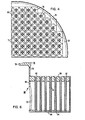
- the lower plate 54 has holes 64 typically of oval shape. Each hollow member 58 is surrounded by four holes 64.
- the plate 54 also has pin holes 71 which serve to center the guides 41 and 43.
- the guides have pins (not shown) at the top which enter holes 71.
- the lower and upper plates 54 and 56 are circular and the hollow members 58 are substantially uniformly spaced in the circularly cylindrical volume defined between the plates 54 and 56.
- the plates are surrounded by a shell 66 (Fig. 6), which is of composite structure and includes a lower section 68 containing openings 72 which are coaxial with the openings 61 in the barrel 57 and which are spaced to mate with the openings 61.
- a supporting cylinder or shell 74 extends from the upper support plate 56 and includes an upper cylindrical section 76 and a flange member 78.
- the section 76 is welded at its lower end to the upper plate 56 and the flange member 78 is welded to the upper end of the section 76.
- the upper internals 37 and the calandria 39 are contained in a barrel 57 (Fig. 2).
- the barrel 57 is circularly cylindrical and it has holes 61 below the top which are shaped to mate with the rims of contiguous outlet nozzles 25 and with the holes 72 in the shell 66 of the calandria.
- the barrel 57 has a flange 65 at the top; at its lower end the barrel 57 supports the upper core plate 33.
- the guides 41 and 43 are closely packed except near the periphery. Coolant flowing from the core 27 into the spaces between the guides therefore has a high velocity and tends to flow towards the periphery. The pressure of this coolant decreases from the bottom of the upper internals 37 to the top. To suppress transverse flow of coolant under the pressure between the closely spaced guides 41 and 43 and the relatively free volume at the periphery of the upper internals 37, horizontal former plates 67 extend along the barrel 57.
- the core 27, upper internals 37 and calandria 39 are enclosed in an outer barrel 81.
- the lower core plate 35 is mounted on the lower end of this barrel 81.
- the barrel 81 has a flange 85.
- the barrel 81 has openings located and shaped to mate with the boundaries of the openings 61 in the calandria shell 66 and coaxial with the contiguous outlet nozzles 25.
- the core 27, the upper internals 37, and the calandria 39 are mounted generally coaxially.
- the upper core plate 33 has pins 87 (Figs. 1, 2) which engage and center the fuel elements 29.
- the cylinder 76 and the shell 60, the barrel 57 and the barrel 81 are mounted generally coaxially with each other and with the core 27, the upper internals 37 and the calandria 39.
- the flange 85 rests on a ledge 89 in the inner surface of body 15.
- the flange 65 of barrel 57 is above flange 85 and a spring (not shown) is interposed between these flanges.
- the flange 78 is disposed upon flange 65.
- the shell 66, the barrel 57 and the barrel 85 are oriented circumferentially so that the boundaries 91 and 93 of the openings 72 and 61 mate with each other, the boundaries 93 (Fig. 1) of the openings 61 in barrel 57 mate with the boundaries 95 of the openings in barrel 81, and the boundaries 95 of the openings in barrel 81 mate with the inner rims 97 of the outlet nozzles 25.
- the annulus 99 between the barrel 81 and the body 15 provides for communication between the inlet nozzles 23 and the lower end of the core 27.
- the coolant which enters through the inlet nozzles 23 flows down through the annulus 99 into bowl 17, thence up through the core 27 and straight up through the upper internals 37 into the calandria 39 where it flows generally transversely to and through the outlet nozzles 25.
- the joints between the boundaries 91, 93 and 93, 95 and between the boundaries 95 and the rims 97 form pressure-tight seals at the outlet nozzles so that there is minimal or no by-pass flow of the coolant from the annulus 99 directly through the outlet nozzles 25.
- the outflow channels of the outlet nozzles 25 are just above the upper internals and substantially at the level of the hollow members 58 of the calandria 39 so that the coolant which passes through the calandria flows directly out of the outlet nozzles 25.
- the lower plate 54 of the calandria 39 is mounted contiguous to the top of the upper internals 37 and the coolant flows into the calandria through the openings in guides 41 and 43, through the spaces between these guides and through the gaps between the formers 67 and the periphery 69 of the upper internals.
- the calandria 39 serves as upper support for the upper internals.
- the driva rods 101 (Fig. 5) for the control rods pass through the hollow members 58 of the calandria and are protected by these members from the coolant flowing radially outwardly to the outlet nozzles 25 at high flow velocities.
- the plates 54 and 56 and the hollow members 58 of the calandria are composed of stainless steel.
- the outlet nozzles 25, typically, are about 1 m in diameter.
- the hollow members 58 typically, have an outer diameter of 8.8 cm, an inner diameter of 5.5 cm and a length of about 125 cm.
- Fig. 7 wherein functionally similar components are identified by numerals corresponding to Fig. 1.
- the calandria is funnel-shaped in cross-section with radially outwardly increasing flow cross-section to cause a substantial reduction of the coolant flow speed where its flow direction is turned downwardly to the outlet nozzles 25.
- control rods and control-rod drives are protected from the outwardly directed high speed coolant flow since, within the calandria in which such radial flow takes place, the drive rods are disposed within contiguous protective tubes and in the area below the calandria there is no radial but only axial flow which does not cause rod vibration.
- the calandria when arranged above the travel area of the control rods that is, above the rod clusters when removed from the core 27, requires only a relatively small amount of tubes 58 corresponding to the amount of control rods as compared to a calandria structure arranged directly above the core 27 which would require a tube for each control rod.
- the outlet nozzles 25 may be placed lower than the calandria 39 so that radial coolant flow out of the calandria is first turned downwardly into annular space 160 before entering the radial outlet nozzle 25.
- radial outflow out of the calandria is more even but the flow has to turn downwardly at the outer circumference of the calandria and then again outwardly into the outlet nozzles 25.
- the calandria 39 may have bottom and top plates 181 and 161 so shaped that the space 163 therebetween diverges in flow direction so that the coolant flow at the outer circumference of the calandria is relatively slow so as to cause only a relatively small pressure drop at its turning point. It may also be noted from Fig. 7 that, with this arrangement, the calandria 39, which as shown, is supported on its lower support plate 181, extends into the reactor head 19 which permits the use of a reactor vessel of lower height than with the arrangement as shown in Fig. 1.
Landscapes
- Physics & Mathematics (AREA)
- Engineering & Computer Science (AREA)
- Plasma & Fusion (AREA)
- General Engineering & Computer Science (AREA)
- High Energy & Nuclear Physics (AREA)
- Monitoring And Testing Of Nuclear Reactors (AREA)
- Structure Of Emergency Protection For Nuclear Reactors (AREA)
Priority Applications (2)
| Application Number | Priority Date | Filing Date | Title |
|---|---|---|---|
| DE8383104721T DE3373586D1 (en) | 1983-05-13 | 1983-05-13 | Nuclear reactor |
| EP83104721A EP0125326B1 (de) | 1983-05-13 | 1983-05-13 | Kernreaktor |
Applications Claiming Priority (1)
| Application Number | Priority Date | Filing Date | Title |
|---|---|---|---|
| EP83104721A EP0125326B1 (de) | 1983-05-13 | 1983-05-13 | Kernreaktor |
Publications (2)
| Publication Number | Publication Date |
|---|---|
| EP0125326A1 true EP0125326A1 (de) | 1984-11-21 |
| EP0125326B1 EP0125326B1 (de) | 1987-09-09 |
Family
ID=8190463
Family Applications (1)
| Application Number | Title | Priority Date | Filing Date |
|---|---|---|---|
| EP83104721A Expired EP0125326B1 (de) | 1983-05-13 | 1983-05-13 | Kernreaktor |
Country Status (2)
| Country | Link |
|---|---|
| EP (1) | EP0125326B1 (de) |
| DE (1) | DE3373586D1 (de) |
Cited By (8)
| Publication number | Priority date | Publication date | Assignee | Title |
|---|---|---|---|---|
| FR2595501A1 (fr) * | 1986-03-07 | 1987-09-11 | Framatome Sa | Equipements internes de reacteurs nucleaires a cuve allongee |
| EP0251822A1 (de) * | 1986-07-03 | 1988-01-07 | Westinghouse Electric Corporation | Vorrichtung und Methode zur Einpassung von Einsatzpassstücken für den Ersatz der oberen Core-Abdeckplatte eines Kernreaktors |
| US4752441A (en) * | 1985-11-14 | 1988-06-21 | Westinghouse Electric Corp. | Modular former for inner barrel assembly of pressurized water reactor |
| US4788032A (en) * | 1986-04-01 | 1988-11-29 | Framatome | Nuclear reactor with flow guidance in the upper internals |
| US5237595A (en) * | 1990-02-26 | 1993-08-17 | Westinghouse Electric Corp. | Guide plate for guide tubes used in nuclear reactors |
| EP0717265A1 (de) | 1994-12-02 | 1996-06-19 | Commissariat A L'energie Atomique | Magnetischer Kodierer zur Markierungslesung einer magnetischen Spur |
| EP0994488A1 (de) * | 1998-10-15 | 2000-04-19 | Mitsubishi Heavy Industries, Ltd. | Obere Kerntrageinbauten für Kernreaktor mit Kühlmittelstromberuhigungseinrichtung |
| CN114093537A (zh) * | 2021-10-29 | 2022-02-25 | 中广核研究院有限公司 | 核反应堆模型 |
Citations (4)
| Publication number | Priority date | Publication date | Assignee | Title |
|---|---|---|---|---|
| US2990349A (en) * | 1955-09-12 | 1961-06-27 | Walter G Roman | Reactor |
| GB907816A (en) * | 1959-01-29 | 1962-10-10 | Atomic Energy Commission | Merchant marine ship reactor |
| DE2143494A1 (de) * | 1970-09-09 | 1972-06-08 | Babcock & Wilcox Co | Druckwasserreaktor |
| FR2382747A1 (fr) * | 1977-03-02 | 1978-09-29 | Combustion Eng | Reacteur nucleaire a refroidissement par eau |
-
1983
- 1983-05-13 DE DE8383104721T patent/DE3373586D1/de not_active Expired
- 1983-05-13 EP EP83104721A patent/EP0125326B1/de not_active Expired
Patent Citations (4)
| Publication number | Priority date | Publication date | Assignee | Title |
|---|---|---|---|---|
| US2990349A (en) * | 1955-09-12 | 1961-06-27 | Walter G Roman | Reactor |
| GB907816A (en) * | 1959-01-29 | 1962-10-10 | Atomic Energy Commission | Merchant marine ship reactor |
| DE2143494A1 (de) * | 1970-09-09 | 1972-06-08 | Babcock & Wilcox Co | Druckwasserreaktor |
| FR2382747A1 (fr) * | 1977-03-02 | 1978-09-29 | Combustion Eng | Reacteur nucleaire a refroidissement par eau |
Cited By (10)
| Publication number | Priority date | Publication date | Assignee | Title |
|---|---|---|---|---|
| US4752441A (en) * | 1985-11-14 | 1988-06-21 | Westinghouse Electric Corp. | Modular former for inner barrel assembly of pressurized water reactor |
| FR2595501A1 (fr) * | 1986-03-07 | 1987-09-11 | Framatome Sa | Equipements internes de reacteurs nucleaires a cuve allongee |
| EP0238390A1 (de) * | 1986-03-07 | 1987-09-23 | Framatome | Innere Struktur eines Kernreaktors mit länglichem Druckbehälter |
| US4788032A (en) * | 1986-04-01 | 1988-11-29 | Framatome | Nuclear reactor with flow guidance in the upper internals |
| EP0251822A1 (de) * | 1986-07-03 | 1988-01-07 | Westinghouse Electric Corporation | Vorrichtung und Methode zur Einpassung von Einsatzpassstücken für den Ersatz der oberen Core-Abdeckplatte eines Kernreaktors |
| US5237595A (en) * | 1990-02-26 | 1993-08-17 | Westinghouse Electric Corp. | Guide plate for guide tubes used in nuclear reactors |
| EP0717265A1 (de) | 1994-12-02 | 1996-06-19 | Commissariat A L'energie Atomique | Magnetischer Kodierer zur Markierungslesung einer magnetischen Spur |
| EP0994488A1 (de) * | 1998-10-15 | 2000-04-19 | Mitsubishi Heavy Industries, Ltd. | Obere Kerntrageinbauten für Kernreaktor mit Kühlmittelstromberuhigungseinrichtung |
| CN114093537A (zh) * | 2021-10-29 | 2022-02-25 | 中广核研究院有限公司 | 核反应堆模型 |
| CN114093537B (zh) * | 2021-10-29 | 2024-11-08 | 中广核研究院有限公司 | 核反应堆模型 |
Also Published As
| Publication number | Publication date |
|---|---|
| EP0125326B1 (de) | 1987-09-09 |
| DE3373586D1 (en) | 1987-10-15 |
Similar Documents
| Publication | Publication Date | Title |
|---|---|---|
| US4716013A (en) | Nuclear reactor | |
| JP5542062B2 (ja) | 原子炉圧力容器のための中性子遮蔽パネル | |
| US3725199A (en) | Nuclear reactor organization and fuel assembly arrangement | |
| US4173513A (en) | Nuclear reactor with control rods | |
| US3821079A (en) | Pressurized water nuclear reactor with upper and lower core support and positioning means | |
| US4759904A (en) | Pressurized water reactor having improved calandria assembly | |
| US4053358A (en) | Modular assembly for supporting, straining, and directing flow to a core in a nuclear reactor | |
| US3253999A (en) | Boiling water nuclear reactor with improved vapor separating arrangement | |
| EP0125326B1 (de) | Kernreaktor | |
| JPH03137597A (ja) | 制御棒案内・支持構造 | |
| US4842813A (en) | Nuclear reactor having a longitudinally elongated vessel | |
| EP0212257B1 (de) | Kernreaktorcoreanordnung mit Neutronenreflektor | |
| US4716012A (en) | Reactor internals loose parts strainer | |
| US4077835A (en) | Nuclear reactor with self-orificing radial blanket | |
| US3403076A (en) | Molten salt breeder reactor and fuel cell for use therein | |
| US4788033A (en) | Calandria | |
| US4659539A (en) | Nuclear reactor | |
| US4654185A (en) | Deep beam reactor vessel head and nuclear reactor including same | |
| US5857006A (en) | Chimney for enhancing flow of coolant water in natural circulation boiling water reactor | |
| US5282232A (en) | Nuclear reactor upper internal equipment with cluster guide devices | |
| JPH0464038B2 (de) | ||
| US4793966A (en) | Nuclear reactor | |
| KR910003803B1 (ko) | 원 자 로 | |
| US3509023A (en) | Nuclear reactor plant | |
| EP0363710A2 (de) | Kombinierte Stützsäule und Führungsrohr zur Anwendung in einem Kernreaktor |
Legal Events
| Date | Code | Title | Description |
|---|---|---|---|
| PUAI | Public reference made under article 153(3) epc to a published international application that has entered the european phase |
Free format text: ORIGINAL CODE: 0009012 |
|
| AK | Designated contracting states |
Designated state(s): BE DE FR GB IT SE |
|
| 17P | Request for examination filed |
Effective date: 19850417 |
|
| 17Q | First examination report despatched |
Effective date: 19860421 |
|
| ITF | It: translation for a ep patent filed | ||
| GRAA | (expected) grant |
Free format text: ORIGINAL CODE: 0009210 |
|
| AK | Designated contracting states |
Kind code of ref document: B1 Designated state(s): BE DE FR GB IT SE |
|
| ET | Fr: translation filed | ||
| REF | Corresponds to: |
Ref document number: 3373586 Country of ref document: DE Date of ref document: 19871015 |
|
| PLBE | No opposition filed within time limit |
Free format text: ORIGINAL CODE: 0009261 |
|
| STAA | Information on the status of an ep patent application or granted ep patent |
Free format text: STATUS: NO OPPOSITION FILED WITHIN TIME LIMIT |
|
| 26N | No opposition filed | ||
| PGFP | Annual fee paid to national office [announced via postgrant information from national office to epo] |
Ref country code: SE Payment date: 19910402 Year of fee payment: 9 |
|
| PGFP | Annual fee paid to national office [announced via postgrant information from national office to epo] |
Ref country code: BE Payment date: 19910415 Year of fee payment: 9 |
|
| PGFP | Annual fee paid to national office [announced via postgrant information from national office to epo] |
Ref country code: FR Payment date: 19910419 Year of fee payment: 9 |
|
| ITTA | It: last paid annual fee | ||
| PGFP | Annual fee paid to national office [announced via postgrant information from national office to epo] |
Ref country code: DE Payment date: 19910628 Year of fee payment: 9 |
|
| PG25 | Lapsed in a contracting state [announced via postgrant information from national office to epo] |
Ref country code: SE Effective date: 19920514 |
|
| PG25 | Lapsed in a contracting state [announced via postgrant information from national office to epo] |
Ref country code: BE Effective date: 19920531 |
|
| BERE | Be: lapsed |
Owner name: WESTINGHOUSE ELECTRIC CORP. Effective date: 19920531 |
|
| PG25 | Lapsed in a contracting state [announced via postgrant information from national office to epo] |
Ref country code: FR Effective date: 19930129 |
|
| PG25 | Lapsed in a contracting state [announced via postgrant information from national office to epo] |
Ref country code: DE Effective date: 19930202 |
|
| REG | Reference to a national code |
Ref country code: FR Ref legal event code: ST |
|
| EUG | Se: european patent has lapsed |
Ref document number: 83104721.2 Effective date: 19921204 |
|
| PGFP | Annual fee paid to national office [announced via postgrant information from national office to epo] |
Ref country code: GB Payment date: 19960412 Year of fee payment: 14 |
|
| PG25 | Lapsed in a contracting state [announced via postgrant information from national office to epo] |
Ref country code: GB Effective date: 19970513 |
|
| GBPC | Gb: european patent ceased through non-payment of renewal fee |
Effective date: 19970513 |