EP0125377A2 - Embrayage avec disque de friction et ressort-diaphragme, particulièrement pour véhicule automobile - Google Patents
Embrayage avec disque de friction et ressort-diaphragme, particulièrement pour véhicule automobile Download PDFInfo
- Publication number
- EP0125377A2 EP0125377A2 EP84100726A EP84100726A EP0125377A2 EP 0125377 A2 EP0125377 A2 EP 0125377A2 EP 84100726 A EP84100726 A EP 84100726A EP 84100726 A EP84100726 A EP 84100726A EP 0125377 A2 EP0125377 A2 EP 0125377A2
- Authority
- EP
- European Patent Office
- Prior art keywords
- pressure plate
- clutch
- belts
- clutch housing
- diaphragm spring
- Prior art date
- Legal status (The legal status is an assumption and is not a legal conclusion. Google has not performed a legal analysis and makes no representation as to the accuracy of the status listed.)
- Granted
Links
Images
Classifications
-
- F—MECHANICAL ENGINEERING; LIGHTING; HEATING; WEAPONS; BLASTING
- F16—ENGINEERING ELEMENTS AND UNITS; GENERAL MEASURES FOR PRODUCING AND MAINTAINING EFFECTIVE FUNCTIONING OF MACHINES OR INSTALLATIONS; THERMAL INSULATION IN GENERAL
- F16D—COUPLINGS FOR TRANSMITTING ROTATION; CLUTCHES; BRAKES
- F16D13/00—Friction clutches
- F16D13/58—Details
- F16D13/70—Pressure members, e.g. pressure plates, for clutch-plates or lamellae; Guiding arrangements for pressure members
- F16D13/71—Pressure members, e.g. pressure plates, for clutch-plates or lamellae; Guiding arrangements for pressure members in which the clutching pressure is produced by springs only
-
- F—MECHANICAL ENGINEERING; LIGHTING; HEATING; WEAPONS; BLASTING
- F16—ENGINEERING ELEMENTS AND UNITS; GENERAL MEASURES FOR PRODUCING AND MAINTAINING EFFECTIVE FUNCTIONING OF MACHINES OR INSTALLATIONS; THERMAL INSULATION IN GENERAL
- F16D—COUPLINGS FOR TRANSMITTING ROTATION; CLUTCHES; BRAKES
- F16D13/00—Friction clutches
- F16D13/58—Details
- F16D13/70—Pressure members, e.g. pressure plates, for clutch-plates or lamellae; Guiding arrangements for pressure members
- F16D2013/706—Pressure members, e.g. pressure plates, for clutch-plates or lamellae; Guiding arrangements for pressure members the axially movable pressure plate is supported by leaf springs
Definitions
- the invention relates to a clutch with a friction plate, the axially movable pressure plate being pressed by means of a diaphragm spring over the friction plate onto the flywheel and the pressure plate being connected to the clutch housing via flexible bands.
- these flexible belts The primary purpose of these flexible belts is to transmit the torque emitted by the motor to the pressure plate and to guide the pressure plate centrally. In some cases, these belts also have the task of lifting the pressure plate off the friction plate when the clutch is disengaged; the straps are preloaded accordingly.
- the aim of the invention is to remedy the disadvantage mentioned without disadvantageous constructive solutions.
- the invention is based on the knowledge that a force can be generated by a new arrangement of the flexible bands, which is added to the spring force of the diaphragm spring while increasing its spring force and thereby increases the torque transmission capacity of the clutch, so that the sliding torque of the clutch despite wear of the friction linings is not reduced.
- the invention thus relates to a clutch with a diaphragm spring friction plate, in particular for motor vehicles, with flexible belts connecting the clutch housing and the pressure plate and dragging the pressure plate with the rotation of the clutch housing, the belts enclosing an angle of at least 5 ° greater than the pressure plate surface from the length between the inclusion points of the tape and from the Size of the permitted wear of the friction elements calculated angle value, and wherein the inclusion point of the belts located on the clutch housing is closer to the flywheel surface than their inclusion point located on the pressure plate.
- the bands are rotatably fastened both on the clutch housing and on the pressure plate in their own surface.
- the use of the invention has several advantages, because the invention allows a clutch with a higher torque to be built using the same diaphragm spring; the disengagement device is less stressed; the behavior of the coupling due to wear is compensated by the flexible belts.
- Another advantage can be that the tapes are not increasingly stressed with increasing wear.
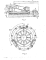
- Fig. 1 and 2 illustrated coupling consists in the known manner, of a coupling housing 1, a pressure plate 2, from an M embranfeder 3 and from a friction plate 6.
- the clutch housing 1 is fastened by means of screws 4 to a flywheel 5 of an internal combustion engine.
- the pressure plate 2 is connected to the clutch housing 1 by means of bands 7, which are arranged radially at a distance from the clutch axis and extend tangentially to it. In the illustrated case, three bands are arranged, but their number can be increased if necessary.
- the belts 7 are fastened to the clutch housing 1 and to the pressure plate 2 by means of their pivoting about bolts 8 which permit pivot axes running parallel to the coupling axis.
- the clutch rotates in the direction indicated by the arrow in Fig. 2; the clutch housing 1 takes the pressure plate 2 by means of the belts 7 by train.
- a collecting surface or support surface parallel to the pressure plate surface is formed, and on these collecting surfaces the belts 7 are on the underside of the band end fastened to the pressure plate 2 or on the flywheel 5 facing the flywheel 5 turned away from the top of their attached to the clutch housing 1 band end.
- the collecting surface formed on the pressure plate 2 is arranged at a greater axial distance from the surface of the flywheel 5 than the collecting surface on the clutch housing, the band 7 is double angled, one end of the band being angled towards the opposite side of the band surface than that the other band end and the band ends form an obtuse angle with the band surface, and its band section between its two clamping or inclusion points encloses an angle with the surface of the pressure plate 2.
- the inclusion point is to be understood as those points of the band 7 between which the deformation thereof is not limited by support. In this case, they are two Inclusion points the corner 9 of the collecting surface on the clutch housing 1 and the corner 10 of the collecting surface on the pressure plate 2.
- a proportionally weaker diaphragm spring can be used for the same clutch. In this case, the load on the lifting device becomes smaller.
- the torque transmission capacity of the clutch can be kept essentially at the same level over the entire life of the friction lining, and the characteristics of the force and the torque are much flatter.
- the constructive means required for this are simple and cheap and do not require any modifications worth mentioning in the usual design of the couplings with a diaphragm spring.
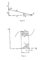
- a force in the band surface also acts on the bands. This arises from the fact that the dimensions of the coupling in the cold and in the warm state are not proportional to each other for the individual coupling parts.
- the pressure plate heats up more than the clutch housing, and its dimensions also change to a greater extent. Therefore, the two ends of the band are not evenly displaced in the radial direction. Therefore, the straps are curved or twisted in their own area if the straps are rigidly attached to the pressure plate or the coupling housing by means of bolts or screws. This strain is very disadvantageous. To avoid this disadvantage, it is therefore preferred to fasten the straps by means of bolts such that their pivoting about the bolt axis is permitted.
Landscapes
- Engineering & Computer Science (AREA)
- General Engineering & Computer Science (AREA)
- Mechanical Engineering (AREA)
- Mechanical Operated Clutches (AREA)
- Springs (AREA)
- Pharmaceuticals Containing Other Organic And Inorganic Compounds (AREA)
- Acyclic And Carbocyclic Compounds In Medicinal Compositions (AREA)
- Medicines Containing Antibodies Or Antigens For Use As Internal Diagnostic Agents (AREA)
- Moving Of Heads (AREA)
Priority Applications (1)
| Application Number | Priority Date | Filing Date | Title |
|---|---|---|---|
| AT84100726T ATE36045T1 (de) | 1983-05-16 | 1984-01-24 | Kupplung mit membranfeder-reibteller, insbesondere fuer kraftfahrzeuge. |
Applications Claiming Priority (2)
| Application Number | Priority Date | Filing Date | Title |
|---|---|---|---|
| HU831688A HU188453B (en) | 1983-05-16 | 1983-05-16 | Diaphramg-spring friction clutch in particular for motor vehicles |
| HU168883 | 1983-05-16 |
Publications (3)
| Publication Number | Publication Date |
|---|---|
| EP0125377A2 true EP0125377A2 (fr) | 1984-11-21 |
| EP0125377A3 EP0125377A3 (en) | 1986-01-02 |
| EP0125377B1 EP0125377B1 (fr) | 1988-07-27 |
Family
ID=10955696
Family Applications (1)
| Application Number | Title | Priority Date | Filing Date |
|---|---|---|---|
| EP84100726A Expired EP0125377B1 (fr) | 1983-05-16 | 1984-01-24 | Embrayage avec disque de friction et ressort-diaphragme, particulièrement pour véhicule automobile |
Country Status (11)
| Country | Link |
|---|---|
| EP (1) | EP0125377B1 (fr) |
| AT (1) | ATE36045T1 (fr) |
| BG (1) | BG43529A3 (fr) |
| CS (1) | CS254323B2 (fr) |
| DD (1) | DD221801A5 (fr) |
| DE (1) | DE3473012D1 (fr) |
| ES (1) | ES531242A0 (fr) |
| HU (1) | HU188453B (fr) |
| PL (1) | PL152313B1 (fr) |
| SU (1) | SU1351518A3 (fr) |
| YU (1) | YU45620B (fr) |
Cited By (6)
| Publication number | Priority date | Publication date | Assignee | Title |
|---|---|---|---|---|
| US4640398A (en) * | 1984-01-28 | 1987-02-03 | Fichtel & Sachs Ag | Friction clutch with tangential leaf springs |
| FR2781265A1 (fr) * | 1998-07-16 | 2000-01-21 | Mannesmann Sachs Ag | Embrayage a friction auto-renforcant |
| FR2816681A1 (fr) * | 2000-11-14 | 2002-05-17 | Mannesmann Sachs Ag | Ensemble a plateau de pression pour un embrayage |
| FR2822509A1 (fr) * | 2001-03-24 | 2002-09-27 | Zf Sachs Ag | Embrayage multidisque |
| FR2825433A1 (fr) * | 2001-06-01 | 2002-12-06 | Zf Sachs Ag | Ensemble a plateau de pression pour un embrayage |
| WO2016206679A1 (fr) * | 2015-06-24 | 2016-12-29 | Schaeffler Technologies AG & Co. KG | Chaîne cinématique de véhicule automobile munie d'un embrayage à friction et embrayage à friction destiné à une chaîne cinématique de véhicule automobile |
Families Citing this family (1)
| Publication number | Priority date | Publication date | Assignee | Title |
|---|---|---|---|---|
| DE19848584B4 (de) * | 1998-07-16 | 2009-11-26 | Zf Sachs Ag | Selbstverstärkende Reibungskupplung |
Family Cites Families (6)
| Publication number | Priority date | Publication date | Assignee | Title |
|---|---|---|---|---|
| US3695404A (en) * | 1970-08-05 | 1972-10-03 | Luk Lamellen & Kupplungsbau | Clutch plate supported by stressed leaf springs |
| FR2370891A1 (fr) * | 1976-11-12 | 1978-06-09 | Ferodo Sa | Ensemble unitaire pour embrayage a diaphragme, notamment pour vehicule automobile, et embrayage a diaphragme comportant un tel ensemble unitaire |
| FR2407393A1 (fr) * | 1977-10-25 | 1979-05-25 | Ferodo Sa | Mecanisme d'embrayage, et embrayage comportant un tel mecanisme |
| DE2841763A1 (de) * | 1978-09-26 | 1980-04-03 | Luk Lamellen & Kupplungsbau | Reibungskupplung sowie verfahren zur montage von reibungskupplungen |
| DD139153B1 (de) * | 1978-10-16 | 1980-10-01 | Alfred Lorenz | Kupplung,insbesondere fuer kraftfahrzeuge |
| DE3017563A1 (de) * | 1980-05-08 | 1981-11-12 | Fichtel & Sachs Ag, 8720 Schweinfurt | Gezogene membranfederkupplung |
-
1983
- 1983-05-16 HU HU831688A patent/HU188453B/hu not_active IP Right Cessation
-
1984
- 1984-01-24 DE DE8484100726T patent/DE3473012D1/de not_active Expired
- 1984-01-24 EP EP84100726A patent/EP0125377B1/fr not_active Expired
- 1984-01-24 AT AT84100726T patent/ATE36045T1/de not_active IP Right Cessation
- 1984-02-10 DD DD84260006A patent/DD221801A5/de not_active IP Right Cessation
- 1984-03-14 SU SU843709536A patent/SU1351518A3/ru active
- 1984-03-29 CS CS842357A patent/CS254323B2/cs unknown
- 1984-04-03 ES ES531242A patent/ES531242A0/es active Granted
- 1984-04-12 BG BG065074A patent/BG43529A3/xx unknown
- 1984-05-14 YU YU83984A patent/YU45620B/sh unknown
- 1984-05-15 PL PL1984247686A patent/PL152313B1/pl unknown
Cited By (7)
| Publication number | Priority date | Publication date | Assignee | Title |
|---|---|---|---|---|
| US4640398A (en) * | 1984-01-28 | 1987-02-03 | Fichtel & Sachs Ag | Friction clutch with tangential leaf springs |
| FR2781265A1 (fr) * | 1998-07-16 | 2000-01-21 | Mannesmann Sachs Ag | Embrayage a friction auto-renforcant |
| US6189667B1 (en) | 1998-07-16 | 2001-02-20 | Mannesmann Sachs Ag | Self-reinforcing friction clutch |
| FR2816681A1 (fr) * | 2000-11-14 | 2002-05-17 | Mannesmann Sachs Ag | Ensemble a plateau de pression pour un embrayage |
| FR2822509A1 (fr) * | 2001-03-24 | 2002-09-27 | Zf Sachs Ag | Embrayage multidisque |
| FR2825433A1 (fr) * | 2001-06-01 | 2002-12-06 | Zf Sachs Ag | Ensemble a plateau de pression pour un embrayage |
| WO2016206679A1 (fr) * | 2015-06-24 | 2016-12-29 | Schaeffler Technologies AG & Co. KG | Chaîne cinématique de véhicule automobile munie d'un embrayage à friction et embrayage à friction destiné à une chaîne cinématique de véhicule automobile |
Also Published As
| Publication number | Publication date |
|---|---|
| HU188453B (en) | 1986-04-28 |
| SU1351518A3 (ru) | 1987-11-07 |
| PL152313B1 (en) | 1990-12-31 |
| HUT35346A (en) | 1985-06-28 |
| CS235784A2 (en) | 1987-06-11 |
| CS254323B2 (en) | 1988-01-15 |
| YU45620B (sh) | 1992-07-20 |
| DE3473012D1 (en) | 1988-09-01 |
| PL247686A1 (en) | 1985-01-30 |
| ES8507242A1 (es) | 1985-08-16 |
| ES531242A0 (es) | 1985-08-16 |
| BG43529A3 (en) | 1988-06-15 |
| DD221801A5 (de) | 1985-05-02 |
| ATE36045T1 (de) | 1988-08-15 |
| YU83984A (en) | 1988-02-29 |
| EP0125377A3 (en) | 1986-01-02 |
| EP0125377B1 (fr) | 1988-07-27 |
Similar Documents
| Publication | Publication Date | Title |
|---|---|---|
| DE69826657T2 (de) | Flache freilaufkupplungeinheit | |
| DE102008031953B4 (de) | Kupplungsaggregat mit Verschleißnachstelleinrichtung | |
| DE3049645C2 (fr) | ||
| DE8137424U1 (de) | Dämpfungsscheibe | |
| DE2751044A1 (de) | Vorrichtung zur daempfung von drehschwingungen, insbesondere fuer kraftfahrzeugkupplungen | |
| EP1069009B1 (fr) | Rétracteur de ceinture de sécurité avec accouplement par friction | |
| DE3507988A1 (de) | Kuehlsystem fuer eine kupplung | |
| DE2751043A1 (de) | Belagtraegerscheibe, insbesondere fuer reibscheiben, vor allem fuer kraftfahrzeugkupplungen | |
| DE2734630B1 (de) | Zweistraengiges stufenlos einstellbares Kegelscheibenumschlingungsgetriebe mit gleichmaessiger Lastverteilung | |
| DE2733880A1 (de) | Kupplungsscheibe | |
| DE3343878C2 (fr) | ||
| DE3224437C2 (de) | Kupplungsscheibe | |
| EP0125377B1 (fr) | Embrayage avec disque de friction et ressort-diaphragme, particulièrement pour véhicule automobile | |
| DE3306281C2 (fr) | ||
| DE2749177B2 (de) | Wellenkupplung | |
| DE3222953A1 (de) | Kupplungsvorrichtung, insbesondere fuer kraftfahrzeuge | |
| DE2256582B2 (de) | Scheibendämpfungsanordnung für Reibkupplungen | |
| DE2629279C3 (de) | Stufenlos regelbares Keilriemengetriebe | |
| DE19960641A1 (de) | Sich automatisch einstellende Reibungskupplung mit Drehfedergehäuse | |
| EP3234390B1 (fr) | Dispositif de transmission d'un couple d'un moteur à combustion interne vers un groupe auxiliaire | |
| DE3107371C2 (de) | Drehschwingungsgedämpfte Kupplungsscheibe für Kraftfahrzeuge | |
| DE3320549A1 (de) | Torsionsdaempfungsvorrichtung, insbesondere reibungskupplung fuer kraftfahrzeuge | |
| DE3027060C2 (de) | Wellenkupplung | |
| DE102010060703A1 (de) | Riementrieb mit Spannsystem | |
| DE10148435A1 (de) | Reibungskupplung, insbesondere Mehrscheibenkupplung |
Legal Events
| Date | Code | Title | Description |
|---|---|---|---|
| PUAI | Public reference made under article 153(3) epc to a published international application that has entered the european phase |
Free format text: ORIGINAL CODE: 0009012 |
|
| AK | Designated contracting states |
Designated state(s): AT BE CH DE FR GB IT LI LU NL SE |
|
| 17P | Request for examination filed |
Effective date: 19841217 |
|
| PUAL | Search report despatched |
Free format text: ORIGINAL CODE: 0009013 |
|
| AK | Designated contracting states |
Designated state(s): AT BE CH DE FR GB IT LI LU NL SE |
|
| 17Q | First examination report despatched |
Effective date: 19870216 |
|
| GRAA | (expected) grant |
Free format text: ORIGINAL CODE: 0009210 |
|
| AK | Designated contracting states |
Kind code of ref document: B1 Designated state(s): AT BE CH DE FR GB IT LI LU NL SE |
|
| REF | Corresponds to: |
Ref document number: 36045 Country of ref document: AT Date of ref document: 19880815 Kind code of ref document: T |
|
| ITF | It: translation for a ep patent filed | ||
| GBT | Gb: translation of ep patent filed (gb section 77(6)(a)/1977) | ||
| REF | Corresponds to: |
Ref document number: 3473012 Country of ref document: DE Date of ref document: 19880901 |
|
| PLBI | Opposition filed |
Free format text: ORIGINAL CODE: 0009260 |
|
| ET | Fr: translation filed | ||
| 26 | Opposition filed |
Opponent name: FICHTEL & SACHS AG Effective date: 19880929 |
|
| NLR1 | Nl: opposition has been filed with the epo |
Opponent name: FICHTEL & SACHS AG |
|
| PGFP | Annual fee paid to national office [announced via postgrant information from national office to epo] |
Ref country code: NL Payment date: 19890131 Year of fee payment: 9 |
|
| PGFP | Annual fee paid to national office [announced via postgrant information from national office to epo] |
Ref country code: FR Payment date: 19910117 Year of fee payment: 8 |
|
| PGFP | Annual fee paid to national office [announced via postgrant information from national office to epo] |
Ref country code: GB Payment date: 19910122 Year of fee payment: 8 |
|
| PGFP | Annual fee paid to national office [announced via postgrant information from national office to epo] |
Ref country code: SE Payment date: 19910123 Year of fee payment: 8 |
|
| PGFP | Annual fee paid to national office [announced via postgrant information from national office to epo] |
Ref country code: AT Payment date: 19910125 Year of fee payment: 8 |
|
| PGFP | Annual fee paid to national office [announced via postgrant information from national office to epo] |
Ref country code: LU Payment date: 19910128 Year of fee payment: 8 |
|
| ITTA | It: last paid annual fee | ||
| PGFP | Annual fee paid to national office [announced via postgrant information from national office to epo] |
Ref country code: BE Payment date: 19910204 Year of fee payment: 8 |
|
| PGFP | Annual fee paid to national office [announced via postgrant information from national office to epo] |
Ref country code: CH Payment date: 19910218 Year of fee payment: 8 |
|
| PLAB | Opposition data, opponent's data or that of the opponent's representative modified |
Free format text: ORIGINAL CODE: 0009299OPPO |
|
| PGFP | Annual fee paid to national office [announced via postgrant information from national office to epo] |
Ref country code: DE Payment date: 19910402 Year of fee payment: 8 |
|
| R26 | Opposition filed (corrected) |
Opponent name: FICHTEL & SACHS AG Effective date: 19880929 |
|
| EPTA | Lu: last paid annual fee | ||
| RDAG | Patent revoked |
Free format text: ORIGINAL CODE: 0009271 |
|
| STAA | Information on the status of an ep patent application or granted ep patent |
Free format text: STATUS: PATENT REVOKED |
|
| 27W | Patent revoked |
Effective date: 19910812 |
|
| REG | Reference to a national code |
Ref country code: CH Ref legal event code: PL |
|
| GBPR | Gb: patent revoked under art. 102 of the ep convention designating the uk as contracting state | ||
| NLR2 | Nl: decision of opposition | ||
| BERE | Be: lapsed |
Owner name: CSEPEL AUTOGYAR Effective date: 19920131 |
|
| EUG | Se: european patent has lapsed |
Ref document number: 84100726.3 Effective date: 19911227 |