EP0125491A1 - Umlaufmotor - Google Patents
Umlaufmotor Download PDFInfo
- Publication number
- EP0125491A1 EP0125491A1 EP84104001A EP84104001A EP0125491A1 EP 0125491 A1 EP0125491 A1 EP 0125491A1 EP 84104001 A EP84104001 A EP 84104001A EP 84104001 A EP84104001 A EP 84104001A EP 0125491 A1 EP0125491 A1 EP 0125491A1
- Authority
- EP
- European Patent Office
- Prior art keywords
- cylinders
- piston
- cylinder
- axis
- engine
- Prior art date
- Legal status (The legal status is an assumption and is not a legal conclusion. Google has not performed a legal analysis and makes no representation as to the accuracy of the status listed.)
- Granted
Links
- 238000002485 combustion reaction Methods 0.000 claims abstract description 7
- 239000000446 fuel Substances 0.000 claims description 32
- 239000007789 gas Substances 0.000 claims description 6
- 230000008878 coupling Effects 0.000 claims 1
- 238000010168 coupling process Methods 0.000 claims 1
- 238000005859 coupling reaction Methods 0.000 claims 1
- 239000007787 solid Substances 0.000 description 6
- 238000002347 injection Methods 0.000 description 2
- 239000007924 injection Substances 0.000 description 2
- 239000000203 mixture Substances 0.000 description 2
- 238000012986 modification Methods 0.000 description 2
- 230000004048 modification Effects 0.000 description 2
- 241001125877 Gobio gobio Species 0.000 description 1
- 230000000295 complement effect Effects 0.000 description 1
- 239000013078 crystal Substances 0.000 description 1
- 238000006073 displacement reaction Methods 0.000 description 1
- 230000000694 effects Effects 0.000 description 1
- 230000010355 oscillation Effects 0.000 description 1
- 239000002915 spent fuel radioactive waste Substances 0.000 description 1
Images


Classifications
-
- F—MECHANICAL ENGINEERING; LIGHTING; HEATING; WEAPONS; BLASTING
- F02—COMBUSTION ENGINES; HOT-GAS OR COMBUSTION-PRODUCT ENGINE PLANTS
- F02B—INTERNAL-COMBUSTION PISTON ENGINES; COMBUSTION ENGINES IN GENERAL
- F02B57/00—Internal-combustion aspects of rotary engines in which the combusted gases displace one or more reciprocating pistons
- F02B57/08—Engines with star-shaped cylinder arrangements
-
- F—MECHANICAL ENGINEERING; LIGHTING; HEATING; WEAPONS; BLASTING
- F02—COMBUSTION ENGINES; HOT-GAS OR COMBUSTION-PRODUCT ENGINE PLANTS
- F02B—INTERNAL-COMBUSTION PISTON ENGINES; COMBUSTION ENGINES IN GENERAL
- F02B1/00—Engines characterised by fuel-air mixture compression
- F02B1/02—Engines characterised by fuel-air mixture compression with positive ignition
- F02B1/04—Engines characterised by fuel-air mixture compression with positive ignition with fuel-air mixture admission into cylinder
-
- F—MECHANICAL ENGINEERING; LIGHTING; HEATING; WEAPONS; BLASTING
- F02—COMBUSTION ENGINES; HOT-GAS OR COMBUSTION-PRODUCT ENGINE PLANTS
- F02B—INTERNAL-COMBUSTION PISTON ENGINES; COMBUSTION ENGINES IN GENERAL
- F02B75/00—Other engines
- F02B75/16—Engines characterised by number of cylinders, e.g. single-cylinder engines
- F02B75/18—Multi-cylinder engines
- F02B2075/1804—Number of cylinders
- F02B2075/1816—Number of cylinders four
Definitions
- This invention relates to a rotary engine. More particularly, the invention is concerned with a rotary engine of the type in which the pistons and associated cylinders rotate together about a pair of displaced axes with the pistons rotating about its own axis which is displaced from the axis of the cylinders.
- the engine of the invention is of the type in which the pistons and cylinders rotate together.
- U.S. Patent 734,237 to McFarland, Jr. discloses an engine in which the cylinders are radially mounted and the pistons are connected with an eccentric shaft. The cylinders are pivotally suspended at their outer ends.
- U.S. Patent 1,082,569 to Tift discloses pistons carried on an eccentric crank and cylinders which oscillate about a pivot-trunnion such that the pistons are alternately forced into and out of the cylinders.
- the casing is revolvably mounted on journal members.
- U.S. Patent 1,878,561 to Wippermann discloses and eccentric disc to which pistons are connected by means of a pivoting piston rod.
- the cylinder frame is slowly rotated.
- U.S. Patent 1,114,816 to Strapp discloses a rotary engine with cylinders fixed to the housing and rotating therewith, and pistons whose axial centers are offset from the axes of the cylinders.
- the pistons are carried on piston rods with orthogonally related , slotted yokes to provide for the reciprocation within the cylinders as the pistons and cylinders rotate.
- U.S. Patent 3.605,564 to Shoemaker is typical of rotary piston devices in which pistons are given rectilinear motion relative to cylinders in which the cylinders rotate about an axis displaced from the axis of rotation of the pistons.
- This patent discloses link rods which pivot both on the piston and a center wheel carrying or rotating the pistons about the axis displaced from the cylinder axis. The cylinders are fixed and rotate with the housing.
- the PCT/AU80/00013 application invented by Richard Gall is an example of the most recent attempt to produce a rotary engine and still has certain drawbacks. In this respect, it is believed that the spark plugs are easily fouled due to centrifugal force.
- Use is made of a conventional coil and distributor. The intake is obtained trough a revolving power shaft into an arcuate conduit and injected into the combustion chamber. Exhaust gases are expelled by an arcuate conduit leading from the exhaust valve to the power shaft and against centrifugal force causing a back pressure.
- a feature of the invention is that the pistons form a solid rotary block which rotates or are connected with a solid block that rotates.
- the cylinders oscillate from right to left and rotate as a unit with the housing while the pistons and the solid block and linkages connected with a plate or plates control the position of the cylinders and their sliding in the housing.
- Drag on the piston is avoided or substantially reduced because the rotary block supporting or carrying the pistons is connected with plates supporting the cylinder (and cylinder heads) and another set of plates are provided which rotate about a fixed offset shaft and are connected with the first set of plates by means of small crankshafts which assure a constant relative position between the pistons and cylinders for each angular position of rotation of the pistons and cylinders as well as maintaining the piston and cylinder rotation together at the same angular speed.
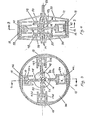
- the engine is shown as a four cylinder engine, although a two or six cylinder or more engine will operate on the same principles.
- cylinders 10a, b, c, and d are supported within a rotary housing 12.
- Housing 12 is fixedly connected with shaft 14 which passes through cylinder axis 16 shown in dashed lines in fig. 2.
- Pistons 20a, b,c and d are each associated with cylinders 10a, b,c and d, respectively, and are connected with a central piston member or block 22 having a portion 24 acting as a piston rod and a piston axis 26 centrally located relative to piston member 22, but displaced from cylinder axis 16.
- the pistons, piston rods and piston member form one solid block.
- the displacement of the two axes 16 and 26 is determined by the length of the cylinders or depth of the bore thereof and the stroke of the pistons 20 such that the piston-cylinder combination will follow a conventional Otto or Diesel engine.
- a pair of spaced cylinder side plates 30 are positioned with cylinders 10 therebetween and rotate togheter with shaft 14 for rotation therewith so that the side plates 30 rotate about cylinder axis 16.
- Each cylinder is connected to each side plate with at least one link 34; however, it is preferred that each cylinder be connected by means of two links 34 to each side plate 30 so that four links 34 interconnect each cylinder with the spaced side plates.
- the cylinders or cylinder head and pistons rotate together or go round together at the same angular velocity so that there is no lateral friction between the pistons and cylinder, and the only friction, if any, is axial as the pistons reciprocate in the cylinders.
- Each link 34 has one end connected to side plate 30 by means of a pivot 36 so that the links can pivot on 36.
- the pivots 36 are equally spaced on opposite sides of the piston axis 26 or center line 38 passing through the centers of the pistons.
- the links are all equal in length and the links associated with one particular cylinder and plate are parallel with each other.
- the cylinder is also provided with pivot 40 to connect the other end of the links to the cylinder; the spacing between the pivots on the cylinder is equal to the spacing between the pivots on the plates so as to assure the longitudinal alignment between the pistons and cylinders.
- Each pair of links 34 are parallel and are of the same length and oscillate between points or pivots 36,40 equidistant from each other so that lines connecting the pivots 36 and 40 together as well as lines passing through the links and connecting the pivot 36 to pivot 40 thereof form a parallelogram.
- the cylinders 10 rotate around center 16, and as cylinder 10 rotates 180° from its top position in figs. 1 and 2, to its bottom position, the relative position or the distance between the piston and cylinder goes from a minimum 42 to a maximum 44 to create the volume variation in the cylinder in the space between the face of the piston and the bottom of the cylinder.
- offset connecting pins 48 are provided which are connected between plates 30a, 30b, and a second pair of spaced plates 50. Plates 50 are fixed with power output shaft 52 for rotation together .
- pins 48 spaced 90°C apart are preferred, although more or less can be used so long as the spacing between each two adjacent pins are the same to maintain the proper balance and to interlock plates 30 and 50.
- the offset connecting pins 48 transfer the power output to plate 30 from plate 50 to power output shaft 52.
- One plate 30a rotates about input shaft 14 which is fixed to housing 12, and for this purpose bearing 46 is provided to rotatably support the first plate 30a.
- the other plate 30 is fixed at fixed connection 32 to output shaft 52 for rotation thereof.
- Offset connecting pins 48 are small crankshafts which have their offset ends 48a, 48b, rotate in bearings 54 and 56 in plates 30 and 50 while at the same time moving plates 30.
- the orientation of the longitudinal axes of crankshafts 48 is parallel to the plane of the axes 16 and.26.
- the second set of plates 50 are carried on and fixed to a shaft 28 , passing through the piston block 22 and has its axis coaxial with piston axis 26.
- plates50 are rotated, and offset connecting pins 48 transfers the rotary movement to plates 30, and from plate 30b to output shaft 52 through fixed
- Conventional intake and exhaust valves 58 and 60 are provided together with a spark plug or piezo-electric crystal 62 which may be provided to ignite the fuel-air mixture.
- FIG. 3 and 4 An alternative embodiment is shown in figs. 3 and 4 which uses slides 18 to connect the cylinders with housing 12 while permitting the cylinders to slide in slides 18 to maintain the cylinder axis 16 aligned with the piston axis 26.
- links 34 and pivots 36,40 are omitted because the relative relationship between the pistons and associated cylinders is maintained by slides 18.
- one plate 30a rotates about shaft 14 at bearing 46, and the other plate 30b is fixed with output shaft 52.
- the piston block 22 upon rotation thereof by the normal movement of the pistons out of the cylinders rotates plates 50 which in turn rotate plates 30 through their interconnection by offset crankshafts 48.
- Shaft 14 is the main supporting shaft and is fixedly connected with housing 12.
- Crankshafts 48 rotate together with plates 46 and 50.
- the offset between the central axis passing through offset 48a and the central axis passing through offset 48b is exactly the same as the spacing between cylinder axis 16 and piston axis 26 and of course, the stroke of the piston in the cylinder is twice the spacing between axes 16 and 26 or 48a and 48b and in effect twice the length of crank 48.
- each offset is parallel with the other as well as with the piston and cylinder axes.
- the four offset crankshafts have their own axis of rotation when they rotate as a group with plates 30 and 50.
- the axis of rotation of the offset cranks 48 is spaced between axis 16 and axis 26, and preferably in the middle between axes 16 and 26. Therefore, each system, the piston system, the cylinder system and the offset cranks rotate about their own individual axis, and all three axes lie in the same plane. Hence, there is no inertial stress on the pistons nor is there a balancing problem when the pistons rotate so that high R.P.M.'s can be achieved.
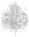
- FIG. 5 illustrates an engine according to the invention of the type schematically shown in figs. 1 and 2, with housing 12 formed of housing elements 112, 114, 116 having an interior opening 118 and a conduit 120 axially traversing the housing from front to rear.
- Axle 124 communicates with the outside of housing 12 for supplying air to the motor as will be explained in connection with figs. 6 and 7.
- Rotor 126 carries the pistons 10 and piston block 22 for rotation about axis X-X which coincides with piston block axis 26.
- Rotor 126 includes a first trunk 127, an intermediate trunk 128 and a final or end trunk 129.
- Pistons 20 are suitably connected with piston rods 130, and are provided with piston rings 132.
- the cylinder has its bottom closed by plate 35.
- the rotor complex is intermediate the side plates 30 and receives ends 48a of the offset cranks 48.
- Plate 30 is solidly connected through flange 140 to output shaft 52.
- the offset crankshafts 48 rotate on bearings mounted in plates 30, and preferably four are provided on each side of the rotor or piston block. As heretofore described the offset crankshafts have their own center of rotation.
- Air or air-fuel combination compressed in cylinders 10 escapes through conduit 142 into the upper part of the cylinder to help scavenge the residual combusted gas and fills the cylinder with fresh air or air-fuel. Additional air is fed through conduit 143 in the input shaft 14, conduit 144 in piston rod 130 and conduit 145. Hole 146 provides entry from conduit 143 to 144. Turbocharger 147 which is activated by turbine 148 feeds the exhaust air to conduit 143 by external means not shown. Fuel is ignited by a typical spark plug 149.
- Nozzle 47 is situated on top of the rotating cylinder 10 and oriented so that is is slightly inclined towards the plane of rotation and the power output shaft 52 so that the output gases impinge onto the blades of a deflector 151, so that the turbine 148 operates the turbocharger 147, the compressed air of which is sucked throught opening 153 and forcefully blasted into collector 152 and into conduit 143.
- Deflector 151 is concentric with axis Y-Y and extends circularly concentric with axis Y-Y.
- Bevel gear 154 forms a solid unit with turbocharger 147 so that it is driven at the start of the engine and then can be disconnected.
- a separate electric motor can be used as the starting motor.
- Combusted gases are collected into collector 155 and then discharged into the atmosphere.
- Bevel gear 55 is connected with shaft 52 and in turn drives complementary bevel gear 156 to supply movement to auxiliary equipment such as a fuel pump through a spur gear 157.
- a fuel pump activated by axle 158 supplies fuel to inlet 159 thorugh aninternal passage 160 into shaft 12 to the complex collector distributor 161 to each cylinder by means of internal passageway 163 to a small tube 164 welded inside conduit 144 of the piston rod.
- Fuel is forced into nozzle 165 and sprayed or atomized into the combustion chamber 166 where it is ignited by spark plug 149.
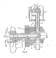
- Fig. 6 illustrates the injection of fuel directly into the combustion chamber and air is supplied separately; like parts have been numbered with the same numbering as in the previous figures.
- Air from the turbocharger is fed to inlet 70 and fuel from the fuel injection pump is led to inlet 159 to fuel conduit 160 comprising conduit portions 71, 72, 73, 74, 75, 76.
- Fig. 7 illustrates how the air and fuel are mixed together in conduits 143 and 144, and it is noted that like parts have the same reference numberals as in the previous figures.
- Air from the turbocharger is fed to inlet 77 to combine with fuel from the fuel pump which is fed in at 78 to combine with the air in conduit 143.
- the arrows show the direction of flow of the fuel and air into the cylinders.
- Port G in fig. 6 can be used both as an exhaust and an intake port.
- the spent fuel escapes through port G into duct 146 through nozzle 47.
- Fuel can be injected directly into the air supplied by the turbocharger by means of a bypass of the fuel line in conduit 143 which may be atomized through a nozzle situated in a conventient position in the air supplied from the turbocharger and then through passageways or conduits 142, 144 and 145 into the upper chamber of the cylinder.
- all passageways 143, 144, 145, 142 could be considered as a manifold when compared to a conventional engine. This type of feeding of fuel through a manifold like system is considered to be useful when starting a cold engine.
- Tube 69 which is contained within conduit 144 is intended to lubricate the piston.
Landscapes
- Engineering & Computer Science (AREA)
- Chemical & Material Sciences (AREA)
- Combustion & Propulsion (AREA)
- Mechanical Engineering (AREA)
- General Engineering & Computer Science (AREA)
- Supercharger (AREA)
- Transmission Devices (AREA)
- Valve Device For Special Equipments (AREA)
- Valve-Gear Or Valve Arrangements (AREA)
- Cylinder Crankcases Of Internal Combustion Engines (AREA)
Applications Claiming Priority (2)
| Application Number | Priority Date | Filing Date | Title |
|---|---|---|---|
| US06/483,602 US4612882A (en) | 1983-04-11 | 1983-04-11 | Rotating cylinder internal combustion engine |
| US483602 | 1990-02-22 |
Publications (2)
| Publication Number | Publication Date |
|---|---|
| EP0125491A1 true EP0125491A1 (de) | 1984-11-21 |
| EP0125491B1 EP0125491B1 (de) | 1988-07-13 |
Family
ID=23920741
Family Applications (1)
| Application Number | Title | Priority Date | Filing Date |
|---|---|---|---|
| EP84104001A Expired EP0125491B1 (de) | 1983-04-11 | 1984-04-10 | Umlaufmotor |
Country Status (5)
| Country | Link |
|---|---|
| US (1) | US4612882A (de) |
| EP (1) | EP0125491B1 (de) |
| JP (1) | JPS6035126A (de) |
| CA (1) | CA1224723A (de) |
| DE (1) | DE3472699D1 (de) |
Families Citing this family (9)
| Publication number | Priority date | Publication date | Assignee | Title |
|---|---|---|---|---|
| US5114321A (en) * | 1991-02-12 | 1992-05-19 | Vairex Corporation | Fluid displacement apparatus with traveling chambers |
| US5303679A (en) * | 1993-08-12 | 1994-04-19 | Vicente Gamon | Rotary internal combustion engine |
| JPH10500186A (ja) * | 1994-02-18 | 1998-01-06 | コンティニュアス サイクル エンジン ディベロプメント カンパニー リミテッド | 回転型内燃機関 |
| US5865087A (en) * | 1996-10-18 | 1999-02-02 | Olson; Howard A. | Rotary variable displacement fluid power device |
| JP4605907B2 (ja) * | 1999-03-24 | 2011-01-05 | エフ・エー・フアウ・モトーレンテヒニック・ゲゼルシヤフト・ミト・ベシユレンクテル・ハフツング | 前後で同軸にかつ互いに横方向間隔をおいて配置された軸線平行な2本の軸を連結する連結要素 |
| DE10051271B4 (de) * | 2000-10-16 | 2015-07-16 | Fev Gmbh | In ihrem Verdichtungsverhältnis einstellbare Kolbenbrennkraftmaschine mit integriertem Verstellaktuator |
| US7270092B2 (en) * | 2005-08-12 | 2007-09-18 | Hefley Carl D | Variable displacement/compression engine |
| DE112007003715A5 (de) * | 2007-12-31 | 2010-11-18 | Fev Motorentechnik Gmbh | Parallelkurbelgetriebe |
| CN105450122B (zh) * | 2016-01-14 | 2017-12-15 | 重庆大学 | 一种双馈风电机组机侧变流器igbt器件结温波动抑制方法 |
Citations (5)
| Publication number | Priority date | Publication date | Assignee | Title |
|---|---|---|---|---|
| US1878561A (en) * | 1928-08-22 | 1932-09-20 | Wippermann Erich | Piston internal combustion engine with cylinder stars arranged one behind the other in alpha common frame |
| US3605564A (en) * | 1969-12-22 | 1971-09-20 | Roger C Shoemaker | Rotary piston device |
| DE2536764A1 (de) * | 1975-08-19 | 1977-03-03 | Paul Fleischer | Verbrennungsmotor |
| WO1980002584A1 (en) * | 1979-05-15 | 1980-11-27 | Price Batten Pty Ltd | Rotary radial internal combustion engine |
| GB2110311A (en) * | 1981-11-28 | 1983-06-15 | Rexroth Mannesmann Gmbh | Radial piston machine |
Family Cites Families (14)
| Publication number | Priority date | Publication date | Assignee | Title |
|---|---|---|---|---|
| US345858A (en) * | 1886-07-20 | Geaydon pooee | ||
| DE301715C (de) * | ||||
| US734237A (en) * | 1901-06-03 | 1903-07-21 | John Bruckman | Gas-engine. |
| FR393328A (fr) * | 1908-07-24 | 1908-12-19 | Win D Williams | Perfectionnements aux moteurs |
| US1114816A (en) * | 1911-01-19 | 1914-10-27 | Simeon G Stapp | Rotary hydrocarbon-engine. |
| US1082569A (en) * | 1912-06-24 | 1913-12-30 | William Adelbirt Tift | Gas-engine. |
| FR468414A (fr) * | 1913-02-15 | 1914-07-06 | Henri Leopold Audouit | Moteur à deux temps rotatif sans articulations ni soupapes |
| FR19254E (fr) * | 1913-07-03 | 1914-12-23 | Gratien Elie Nicolas Michaux | Moteur à explosions à récupération du travail des gaz d'échappement et à mise en marche automatique |
| GB130414A (en) * | 1918-02-19 | 1919-08-07 | James Edwin Ellor | Improvements in and relating to Internal Combustion Prime Movers. |
| CH90208A (de) * | 1920-02-26 | 1921-08-01 | Boris Von Loutzkoy | Luftgefederte Nabe. |
| US1508937A (en) * | 1921-11-04 | 1924-09-16 | Micro Meter Company | Meter |
| FR818200A (fr) * | 1936-03-02 | 1937-09-20 | Kinetic Cycle Res Corp | Perfectionnements aux mécanismes pour machines motrices ou pompes |
| US2665668A (en) * | 1949-03-22 | 1954-01-12 | Patrick C Ward | Engine |
| US3242870A (en) * | 1961-10-06 | 1966-03-29 | Stewart Warner Corp | Hydraulic pump or motor |
-
1983
- 1983-04-11 US US06/483,602 patent/US4612882A/en not_active Expired - Lifetime
-
1984
- 1984-04-09 CA CA000451521A patent/CA1224723A/en not_active Expired
- 1984-04-10 DE DE8484104001T patent/DE3472699D1/de not_active Expired
- 1984-04-10 EP EP84104001A patent/EP0125491B1/de not_active Expired
- 1984-04-11 JP JP59071037A patent/JPS6035126A/ja active Pending
Patent Citations (5)
| Publication number | Priority date | Publication date | Assignee | Title |
|---|---|---|---|---|
| US1878561A (en) * | 1928-08-22 | 1932-09-20 | Wippermann Erich | Piston internal combustion engine with cylinder stars arranged one behind the other in alpha common frame |
| US3605564A (en) * | 1969-12-22 | 1971-09-20 | Roger C Shoemaker | Rotary piston device |
| DE2536764A1 (de) * | 1975-08-19 | 1977-03-03 | Paul Fleischer | Verbrennungsmotor |
| WO1980002584A1 (en) * | 1979-05-15 | 1980-11-27 | Price Batten Pty Ltd | Rotary radial internal combustion engine |
| GB2110311A (en) * | 1981-11-28 | 1983-06-15 | Rexroth Mannesmann Gmbh | Radial piston machine |
Also Published As
| Publication number | Publication date |
|---|---|
| US4612882A (en) | 1986-09-23 |
| JPS6035126A (ja) | 1985-02-22 |
| CA1224723A (en) | 1987-07-28 |
| DE3472699D1 (en) | 1988-08-18 |
| EP0125491B1 (de) | 1988-07-13 |
Similar Documents
| Publication | Publication Date | Title |
|---|---|---|
| US3319874A (en) | Variable displacement-variable clearance device | |
| US6915765B1 (en) | Piston engine assembly | |
| EP0357291A2 (de) | Maschine ohne Kurbel | |
| US3182644A (en) | Internal combustion engine | |
| US4625683A (en) | Rotating cylinder internal combustion engine | |
| EP0125491B1 (de) | Umlaufmotor | |
| US3955544A (en) | Internal combustion engine | |
| JPS594530B2 (ja) | 二サイクルエンジン | |
| US1895206A (en) | Swash plate internal combustion engine operating on the two-stroke cycle | |
| JP2001516837A (ja) | 可変圧縮ピストン組立体 | |
| US6032622A (en) | Internal combustion cylinder engine | |
| US7509930B2 (en) | Internal combustion barrel engine | |
| DE69409262T2 (de) | Rotierende brennkraftmaschine | |
| US4834032A (en) | Two-stroke cycle engine and pump having three-stroke cycle effect | |
| US3557761A (en) | Self-charging and -scavenging lever engine | |
| US3550568A (en) | Opposing piston engine | |
| US2079571A (en) | Uniflow gas engine | |
| US3968777A (en) | Internal combustion engine | |
| US4434751A (en) | Rotary piston engine | |
| JP2001521092A (ja) | 2ストロークエンジン | |
| US20070062469A1 (en) | Rotary radial internal combustion piston engine | |
| KR870001889B1 (ko) | 로우터리 엔진(Rotary engine) | |
| DE3207344A1 (de) | Sternmotorkompressor mit x und dreieckhubkolbenstangenfuehrungen am gekoppelten planetentriebwerk | |
| US2088863A (en) | Two-stroke cycle internal combustion engine | |
| US8206129B2 (en) | Supercharged internal combustion engine including a pressurized fluid outlet |
Legal Events
| Date | Code | Title | Description |
|---|---|---|---|
| PUAI | Public reference made under article 153(3) epc to a published international application that has entered the european phase |
Free format text: ORIGINAL CODE: 0009012 |
|
| AK | Designated contracting states |
Designated state(s): DE FR GB IT SE |
|
| 17P | Request for examination filed |
Effective date: 19850515 |
|
| 17Q | First examination report despatched |
Effective date: 19860203 |
|
| GRAA | (expected) grant |
Free format text: ORIGINAL CODE: 0009210 |
|
| AK | Designated contracting states |
Kind code of ref document: B1 Designated state(s): DE FR GB IT SE |
|
| PG25 | Lapsed in a contracting state [announced via postgrant information from national office to epo] |
Ref country code: SE Effective date: 19880713 Ref country code: FR Free format text: THE PATENT HAS BEEN ANNULLED BY A DECISION OF A NATIONAL AUTHORITY Effective date: 19880713 |
|
| REF | Corresponds to: |
Ref document number: 3472699 Country of ref document: DE Date of ref document: 19880818 |
|
| ITF | It: translation for a ep patent filed | ||
| EN | Fr: translation not filed | ||
| PGFP | Annual fee paid to national office [announced via postgrant information from national office to epo] |
Ref country code: GB Payment date: 19890131 Year of fee payment: 6 |
|
| ITTA | It: last paid annual fee | ||
| PLBE | No opposition filed within time limit |
Free format text: ORIGINAL CODE: 0009261 |
|
| STAA | Information on the status of an ep patent application or granted ep patent |
Free format text: STATUS: NO OPPOSITION FILED WITHIN TIME LIMIT |
|
| PGFP | Annual fee paid to national office [announced via postgrant information from national office to epo] |
Ref country code: DE Payment date: 19890518 Year of fee payment: 6 |
|
| 26N | No opposition filed | ||
| PG25 | Lapsed in a contracting state [announced via postgrant information from national office to epo] |
Ref country code: GB Effective date: 19900410 |
|
| GBPC | Gb: european patent ceased through non-payment of renewal fee | ||
| PG25 | Lapsed in a contracting state [announced via postgrant information from national office to epo] |
Ref country code: DE Effective date: 19910101 |