EP0125552A1 - Presse hydraulique - Google Patents
Presse hydraulique Download PDFInfo
- Publication number
- EP0125552A1 EP0125552A1 EP84104805A EP84104805A EP0125552A1 EP 0125552 A1 EP0125552 A1 EP 0125552A1 EP 84104805 A EP84104805 A EP 84104805A EP 84104805 A EP84104805 A EP 84104805A EP 0125552 A1 EP0125552 A1 EP 0125552A1
- Authority
- EP
- European Patent Office
- Prior art keywords
- press
- pressing
- cylinder
- guided
- chamber
- Prior art date
- Legal status (The legal status is an assumption and is not a legal conclusion. Google has not performed a legal analysis and makes no representation as to the accuracy of the status listed.)
- Granted
Links
- 239000002910 solid waste Substances 0.000 claims abstract description 5
- 230000003014 reinforcing effect Effects 0.000 claims description 3
- 239000000463 material Substances 0.000 description 6
- 239000002184 metal Substances 0.000 description 5
- 229910052751 metal Inorganic materials 0.000 description 5
- 238000000034 method Methods 0.000 description 5
- 230000006835 compression Effects 0.000 description 4
- 238000007906 compression Methods 0.000 description 4
- 238000011109 contamination Methods 0.000 description 4
- 239000002699 waste material Substances 0.000 description 4
- 238000012423 maintenance Methods 0.000 description 3
- 230000002787 reinforcement Effects 0.000 description 3
- 229910001018 Cast iron Inorganic materials 0.000 description 1
- 229910001208 Crucible steel Inorganic materials 0.000 description 1
- 230000004308 accommodation Effects 0.000 description 1
- 230000003750 conditioning effect Effects 0.000 description 1
- 238000010276 construction Methods 0.000 description 1
- 238000005202 decontamination Methods 0.000 description 1
- 230000003588 decontaminative effect Effects 0.000 description 1
- 239000012530 fluid Substances 0.000 description 1
- 239000002920 hazardous waste Substances 0.000 description 1
- 239000010720 hydraulic oil Substances 0.000 description 1
- 238000010169 landfilling Methods 0.000 description 1
- 239000003921 oil Substances 0.000 description 1
- 238000004806 packaging method and process Methods 0.000 description 1
- 230000001681 protective effect Effects 0.000 description 1
- 238000005086 pumping Methods 0.000 description 1
- 230000002285 radioactive effect Effects 0.000 description 1
- 239000002901 radioactive waste Substances 0.000 description 1
- 238000001046 rapid expansion of supercritical solution Methods 0.000 description 1
- 238000007789 sealing Methods 0.000 description 1
- 239000007787 solid Substances 0.000 description 1
- 239000000126 substance Substances 0.000 description 1
- 238000009423 ventilation Methods 0.000 description 1
Images


Classifications
-
- B—PERFORMING OPERATIONS; TRANSPORTING
- B30—PRESSES
- B30B—PRESSES IN GENERAL
- B30B1/00—Presses, using a press ram, characterised by the features of the drive therefor, pressure being transmitted directly, or through simple thrust or tension members only, to the press ram or platen
- B30B1/32—Presses, using a press ram, characterised by the features of the drive therefor, pressure being transmitted directly, or through simple thrust or tension members only, to the press ram or platen by plungers under fluid pressure
-
- B—PERFORMING OPERATIONS; TRANSPORTING
- B30—PRESSES
- B30B—PRESSES IN GENERAL
- B30B9/00—Presses specially adapted for particular purposes
- B30B9/30—Presses specially adapted for particular purposes for baling; Compression boxes therefor
-
- B—PERFORMING OPERATIONS; TRANSPORTING
- B30—PRESSES
- B30B—PRESSES IN GENERAL
- B30B9/00—Presses specially adapted for particular purposes
- B30B9/32—Presses specially adapted for particular purposes for consolidating scrap metal or for compacting used cars
Definitions
- the invention relates to a hydraulically driven, vertically operating press for compacting solid waste contained in containers, consisting of a frame with a stationary table and head piece, a press cylinder, a press piston guided therein with a stamp attached to it, a piston rod and a lifting rod. and lowerable, consisting of a tube bale chamber, which is guided in the frame.
- Hydraulic presses are increasingly used to reduce the volume of solid waste that is stored in metal containers or metal drums. This is often hazardous waste generated in the chemical industry, in research institutes and in hospitals. Solid radioactive contaminated special waste in particular, which is generated primarily in nuclear facilities, must be compacted before further conditioning, additional packaging and landfilling. This is often done by compressing closed 100 liter metal drums filled with waste into tablet-like "compact", which in turn is stored in larger landfill drums e.g. can be accommodated in 200 1-metal drums. This compacting is usually carried out with hydraulic high-pressure presses.
- D E -OS 26 59 691 is a hydraulically reasonable t rubbed, vertically operating press for compacting located in containers of radioactive waste described, consisting of a fixed table and head piece, a pressing cylinder with pressing piston and affixed stamp according to the preamble of claim 1.
- this press due to its constructive design, this press has a very high dead weight and a very large space and space requirement. This largely prevents mobile use of this press, and the accommodation of such presses is particularly complex because of the required space, which is expensive anyway for safety and contamination reasons. Disposition, maintenance and decontamination of such large presses, as well as the necessary additional protective measures, such as. B. against contamination of the operating personnel.
- the present invention was therefore based on the object to provide a hydraulically driven, vertically working press for compacting solid waste contained in containers, consisting of a frame with a stationary table and head piece, a press cylinder, a press piston guided therein with a stamp attached to it , a piston rod and a lifting and lowering, consisting of a tube compression chamber, which is guided in the frame, which has a low weight, requires little space and space, is low-maintenance and ensures safe work without endangering the operating personnel.
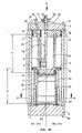
- the press cylinder forms the frame, on the head piece of which the piston rod is fixed, that the press chamber is guided in the press cylinder and the ram in the press chamber, and that the press cylinder in the lower half has at least one loading and Has emptying opening.
- the press cylinder is preferably provided with reinforcing ribs.
- the designed as a base plate table (2) of the hydraulic press is frictionally connected with the head piece (3) by means of the P reßzylinders (1).
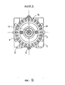
- the press cylinder (1) can have one or two loading openings (27) for the press chamber (25), in which there is a sheet metal drum (26) filled with waste, which to be pressed into a tablet-shaped "compact".
- the loading openings (27) can be provided with an opening transverse reinforcement (22) and can be delimited laterally by guide reinforcements (17).
- the press cylinder (1) can consist of cast iron, cast steel or another suitable material.
- the wall thickness of the press cylinder (1) is designed according to the press pressure.
- the head piece (3) is firmly connected to a piston rod (10) by a threaded nut (11).
- Hydraulic lines (29) lead through the head piece (3) into a hydraulic chamber (30) via hydraulic unit connections (28).
- the hydraulic fluid presses on the piston cover (8), on which the plunger (6) is attached to the plunger base (7).
- the plunger (6) is guided over the piston cover (8) along the piston rod (10) inside and also over the piston cover (8) equipped with sealing elements (12) and guide elements (23) on the inside of the press cylinder (1) and supported.
- the plunger (6) on the guide ring (34) of a pressure plate (15) attached to the plunger base (7) is guided in a press chamber (4) which forms the press chamber (25).
- the press chamber (4) is moved axially by means of the hydraulic auxiliary cylinders (13).
- the press chamber (4) is guided or supported at the top by means of a support ring (5) and at the bottom via bearings (14) of the guide reinforcements (17) located on the press cylinder (1) in the press cylinder (1) (Fig. VII). Due to the double guidance of the plunger (6) and the bale chamber (4), which also has to absorb the lateral press forces when compacting the pressed material, and the long selected guide distances "C” and "D", the plunger (6 ) locked out. Through his Support function, the support ring (5) prevents the press cylinder (1) from constricting in the lower region of the loading openings (27).
- the hydraulic chamber (30) is connected to the annular space (31) which is delimited by the press piston (6) and the piston rod (10).
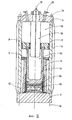
- the annular space (31) thus acts as an additional press cylinder, so that the hydraulically effective total piston surface now consists of the piston cover (8) plus piston crown (7). This results in a low operating pressure with maximum pressing force. It is also possible to do without the piston rod (10) (Fig. III b), especially for smaller presses.
- the pressure plate (15) attached to the underside of the piston head (7) in the direction of the material to be pressed is expediently curved.
- a correspondingly shaped support (20) is attached to the table (2). The resulting greater compression of the compact near its axis reduces its divergence after the compacting process.
- the lower inner wall of the press chamber (4) is lined with a replaceable, hardened wear insert (21).
- the V erschl constitutiondium (21) is constructed suitably slightly conical to facilitate the removal of the compression chamber (4) from the compact (33).
- the height of the V erschl constitutiondes (21) is dimensioned such that it can absorb the lateral pressure during the pressing or Kompakt istsvorganges.
- the pressure plate (15) and the support (20) can advantageously also be made of replaceable, low-wear material. However, it is also possible to insert the support (20) into the table (2) so that the flat upper edge of the support (20) coincides with the upper edge of the table (2).
- Perforation devices (18) for producing ventilation holes in the not yet compacted drums (26) are arranged on the press.
- the drums (26) can by means of rollers or sliding plates (16) in the P RESS are brought position.
- the press cylinder (1) is provided with reinforcing ribs (9). These can e.g. B. welded or cast. It has also turned out to be advantageous, above all for assembly and maintenance reasons, if the press cylinder (1) is connected to the table (2) and the head piece (3) by screws (19).
- the loading openings (27) can optionally be equipped with a suction device which, after the compression chamber (4) has been lifted, removes any contamination after the compacting has been carried out.
- the pressing process using the press according to the invention will be explained below.
- the pressing or compacting process is started by opening the hydraulic connection (32) and flooding the hydraulic chamber (30) with hydraulic oil via the connections ( 28) and the channels (29) initiated.
- the flooding is started with a high volume flow at low pressure.
- the hydraulic pressure reßwiderstand automatically until it reaches the maximum operating pressure.
- the oil escapes from the room via the connection (32), the plunger (6) plunges into the press chamber (25) and compresses the barrel (26) into a tablet-like compact (33).
- the press chambers (4) and the press pistons (6) can be returned to the output or Loading position. This can be done either by pumping out the hydraulic chamber (30) according to Figure III b or by flooding the room (31) according to Figure III a.
- the press cylinder (1) together with the press chamber (4) in the press position, also provides an effective, closed containment to the material to be pressed and thus also offers excellent contamination protection for the operating personnel.
- the press according to the invention can be operated remotely and can be used inexpensively in hot cells and similar rooms.
- the press according to the invention can be used by adapting the press piston (6) and the press chamber (4) with the end of an adapter for compacting differently sized pressed material.
Landscapes
- Engineering & Computer Science (AREA)
- Mechanical Engineering (AREA)
- Physics & Mathematics (AREA)
- Fluid Mechanics (AREA)
- Press Drives And Press Lines (AREA)
- Processing Of Solid Wastes (AREA)
Applications Claiming Priority (2)
| Application Number | Priority Date | Filing Date | Title |
|---|---|---|---|
| DE3317680A DE3317680C1 (de) | 1983-05-14 | 1983-05-14 | Hydraulische Presse |
| DE3317680 | 1983-05-14 |
Publications (2)
| Publication Number | Publication Date |
|---|---|
| EP0125552A1 true EP0125552A1 (fr) | 1984-11-21 |
| EP0125552B1 EP0125552B1 (fr) | 1987-02-04 |
Family
ID=6199037
Family Applications (1)
| Application Number | Title | Priority Date | Filing Date |
|---|---|---|---|
| EP84104805A Expired EP0125552B1 (fr) | 1983-05-14 | 1984-04-28 | Presse hydraulique |
Country Status (3)
| Country | Link |
|---|---|
| EP (1) | EP0125552B1 (fr) |
| JP (1) | JPS59212196A (fr) |
| DE (2) | DE3317680C1 (fr) |
Cited By (3)
| Publication number | Priority date | Publication date | Assignee | Title |
|---|---|---|---|---|
| EP0543177A1 (fr) * | 1991-10-28 | 1993-05-26 | Hideo Hoshi | Vérin hydraulique |
| FR2686830A1 (fr) * | 1992-02-03 | 1993-08-06 | Acb | Presse pour comprimer des futs de dechets contamines. |
| US5662036A (en) * | 1996-02-28 | 1997-09-02 | Compak Filter Services (Franchising) Inc. | Compacting apparatus |
Families Citing this family (6)
| Publication number | Priority date | Publication date | Assignee | Title |
|---|---|---|---|---|
| DE19513846C1 (de) * | 1995-04-12 | 1996-04-25 | Lueer Hans Joachim | Vorrichtung zum Kompaktieren von radioaktiven Abfallstoffen |
| DE19605660A1 (de) * | 1996-02-15 | 1997-08-21 | Big Entwicklungs Und Vermietun | Verdichtungsvorrichtung für radioaktives Material enthaltende Behältnisse |
| CN101209520B (zh) * | 2006-12-29 | 2012-11-14 | 上海第一机床厂有限公司 | 一种导向筒的加工工艺 |
| US8069781B2 (en) | 2008-10-31 | 2011-12-06 | Deere & Company | Agricultural baler |
| RU2453437C2 (ru) * | 2010-04-21 | 2012-06-20 | Открытое акционерное общество "Свердловский научно-исследовательский институт химического машиностроения" (ОАО "СвердНИИхиммаш") | Гидравлический пресс для компактирования твердых отходов в бочке и распрессовки заполненной бочки с крышкой в брикет |
| CN102161239A (zh) * | 2010-12-22 | 2011-08-24 | 中国福马机械集团有限公司 | 连续压机 |
Citations (4)
| Publication number | Priority date | Publication date | Assignee | Title |
|---|---|---|---|---|
| US2150812A (en) * | 1936-04-22 | 1939-03-14 | Frank C Aukerman | Press |
| US2212047A (en) * | 1938-04-15 | 1940-08-20 | John L Ross | Press for crushing cans |
| US3934498A (en) * | 1974-01-31 | 1976-01-27 | Hochanadel Donald L | Compacter for compacting objects such as cans and the like |
| DE2659691A1 (de) * | 1976-12-31 | 1978-11-16 | Kernforschungsz Karlsruhe | Beschickungsanlage fuer faesser mit radioaktivem inhalt |
Family Cites Families (1)
| Publication number | Priority date | Publication date | Assignee | Title |
|---|---|---|---|---|
| DE188079C (fr) * |
-
1983
- 1983-05-14 DE DE3317680A patent/DE3317680C1/de not_active Expired
-
1984
- 1984-04-28 EP EP84104805A patent/EP0125552B1/fr not_active Expired
- 1984-04-28 DE DE8484104805T patent/DE3462315D1/de not_active Expired
- 1984-05-14 JP JP59094788A patent/JPS59212196A/ja active Granted
Patent Citations (4)
| Publication number | Priority date | Publication date | Assignee | Title |
|---|---|---|---|---|
| US2150812A (en) * | 1936-04-22 | 1939-03-14 | Frank C Aukerman | Press |
| US2212047A (en) * | 1938-04-15 | 1940-08-20 | John L Ross | Press for crushing cans |
| US3934498A (en) * | 1974-01-31 | 1976-01-27 | Hochanadel Donald L | Compacter for compacting objects such as cans and the like |
| DE2659691A1 (de) * | 1976-12-31 | 1978-11-16 | Kernforschungsz Karlsruhe | Beschickungsanlage fuer faesser mit radioaktivem inhalt |
Cited By (6)
| Publication number | Priority date | Publication date | Assignee | Title |
|---|---|---|---|---|
| EP0543177A1 (fr) * | 1991-10-28 | 1993-05-26 | Hideo Hoshi | Vérin hydraulique |
| US5410946A (en) * | 1991-10-28 | 1995-05-02 | Mannesmann Rexroth Gmbh | Hydraulic actuator |
| FR2686830A1 (fr) * | 1992-02-03 | 1993-08-06 | Acb | Presse pour comprimer des futs de dechets contamines. |
| EP0555131A1 (fr) * | 1992-02-03 | 1993-08-11 | Gec Alsthom Acb | Presse pour comprimer des fûts de déchets contaminés |
| US5323698A (en) * | 1992-02-03 | 1994-06-28 | Acb | Press for compressing drums of contaminated waste |
| US5662036A (en) * | 1996-02-28 | 1997-09-02 | Compak Filter Services (Franchising) Inc. | Compacting apparatus |
Also Published As
| Publication number | Publication date |
|---|---|
| DE3462315D1 (en) | 1987-03-12 |
| JPS59212196A (ja) | 1984-12-01 |
| DE3317680C1 (de) | 1984-06-20 |
| EP0125552B1 (fr) | 1987-02-04 |
| JPH0475120B2 (fr) | 1992-11-27 |
Similar Documents
| Publication | Publication Date | Title |
|---|---|---|
| DE3036533C2 (de) | Hydraulische Pulverpresse | |
| DE3319698C2 (de) | Transportierbare Presse zum Hochverdichten radioaktiver Abfallstoffe von Kernkraftwerken und Verfahren zum Pressen | |
| EP0125552B1 (fr) | Presse hydraulique | |
| DE2659691C2 (de) | Anlage zum Verpressen von radioaktiven Abfällen in einem Faß | |
| DE2457624A1 (de) | Beschickungs- und vorbehandlungsanlage einer paketierpresse fuer radioaktive abfaelle | |
| DE2157465A1 (de) | Hydraulische blockpresse | |
| DE3638621C2 (fr) | ||
| DE2243136C3 (de) | Verfahren und Einrichtung zur Paketierung von festen radioaktiven oder giftigen Abfallstoffen | |
| WO2003080323A1 (fr) | Presse de traitement de tous types de materiaux | |
| DE2154631C3 (de) | Überlastungsschutzvorrichtung für einen Ladekran | |
| DE2758973C2 (de) | Spindelpresse | |
| CH564467A5 (en) | Equipment for filling and compressing garbage - has arrangement for alternately opening feeder and compressing garbage | |
| DE1800148A1 (de) | Hydraulischer oder pneumatischer Antrieb | |
| CH581542A5 (en) | Hydraulic compactor for household refuse - has container hinged on vertical column and hydraulically actuated compacting plate | |
| DE102019003179A1 (de) | Pressvorrichtung zur Kompaktierung von Behältern mit darin befindlichen Stoffen | |
| EP0623455B1 (fr) | Presse pour le compactage de matériaux, en particulier de déchets | |
| DE2529531A1 (de) | Mit wasser betaetigte verdichtungsvorrichtung | |
| DE3131544C2 (fr) | ||
| DE2252329A1 (de) | Presse mit grossem hub | |
| DE2709890C3 (fr) | ||
| CH568847A5 (en) | Rubbish press with movable housing and press device - rubbish is compressed and ejected through passage released and cut off by trash rack | |
| DE259720C (fr) | ||
| AT163765B (de) | Druckmittelbetriebene Presse mit Ausstoßkolben | |
| DE1502177A1 (de) | Nach Art einer Presse ausgebildete Vorrichtung | |
| DE2949712A1 (de) | Ballenpresse |
Legal Events
| Date | Code | Title | Description |
|---|---|---|---|
| PUAI | Public reference made under article 153(3) epc to a published international application that has entered the european phase |
Free format text: ORIGINAL CODE: 0009012 |
|
| 17P | Request for examination filed |
Effective date: 19840428 |
|
| AK | Designated contracting states |
Designated state(s): BE CH DE FR GB LI SE |
|
| GRAA | (expected) grant |
Free format text: ORIGINAL CODE: 0009210 |
|
| AK | Designated contracting states |
Kind code of ref document: B1 Designated state(s): BE CH DE FR GB LI SE |
|
| REF | Corresponds to: |
Ref document number: 3462315 Country of ref document: DE Date of ref document: 19870312 |
|
| ET | Fr: translation filed | ||
| PLBE | No opposition filed within time limit |
Free format text: ORIGINAL CODE: 0009261 |
|
| STAA | Information on the status of an ep patent application or granted ep patent |
Free format text: STATUS: NO OPPOSITION FILED WITHIN TIME LIMIT |
|
| 26N | No opposition filed | ||
| EAL | Se: european patent in force in sweden |
Ref document number: 84104805.1 |
|
| PGFP | Annual fee paid to national office [announced via postgrant information from national office to epo] |
Ref country code: GB Payment date: 19970314 Year of fee payment: 14 Ref country code: FR Payment date: 19970314 Year of fee payment: 14 |
|
| PGFP | Annual fee paid to national office [announced via postgrant information from national office to epo] |
Ref country code: DE Payment date: 19970320 Year of fee payment: 14 Ref country code: BE Payment date: 19970320 Year of fee payment: 14 |
|
| PGFP | Annual fee paid to national office [announced via postgrant information from national office to epo] |
Ref country code: SE Payment date: 19970324 Year of fee payment: 14 |
|
| PGFP | Annual fee paid to national office [announced via postgrant information from national office to epo] |
Ref country code: CH Payment date: 19970326 Year of fee payment: 14 |
|
| PG25 | Lapsed in a contracting state [announced via postgrant information from national office to epo] |
Ref country code: GB Free format text: LAPSE BECAUSE OF NON-PAYMENT OF DUE FEES Effective date: 19980428 |
|
| PG25 | Lapsed in a contracting state [announced via postgrant information from national office to epo] |
Ref country code: SE Free format text: LAPSE BECAUSE OF NON-PAYMENT OF DUE FEES Effective date: 19980429 |
|
| PG25 | Lapsed in a contracting state [announced via postgrant information from national office to epo] |
Ref country code: LI Free format text: LAPSE BECAUSE OF NON-PAYMENT OF DUE FEES Effective date: 19980430 Ref country code: FR Free format text: THE PATENT HAS BEEN ANNULLED BY A DECISION OF A NATIONAL AUTHORITY Effective date: 19980430 Ref country code: CH Free format text: LAPSE BECAUSE OF NON-PAYMENT OF DUE FEES Effective date: 19980430 Ref country code: BE Free format text: LAPSE BECAUSE OF NON-PAYMENT OF DUE FEES Effective date: 19980430 |
|
| BERE | Be: lapsed |
Owner name: NUKEM G.M.B.H. Effective date: 19980430 |
|
| REG | Reference to a national code |
Ref country code: CH Ref legal event code: PL |
|
| GBPC | Gb: european patent ceased through non-payment of renewal fee |
Effective date: 19980428 |
|
| EUG | Se: european patent has lapsed |
Ref document number: 84104805.1 |
|
| PG25 | Lapsed in a contracting state [announced via postgrant information from national office to epo] |
Ref country code: DE Free format text: LAPSE BECAUSE OF NON-PAYMENT OF DUE FEES Effective date: 19990202 |
|
| REG | Reference to a national code |
Ref country code: FR Ref legal event code: ST |