EP0125585B1 - Equipment for the removal of air out of pulverulent materials - Google Patents
Equipment for the removal of air out of pulverulent materials Download PDFInfo
- Publication number
- EP0125585B1 EP0125585B1 EP84105067A EP84105067A EP0125585B1 EP 0125585 B1 EP0125585 B1 EP 0125585B1 EP 84105067 A EP84105067 A EP 84105067A EP 84105067 A EP84105067 A EP 84105067A EP 0125585 B1 EP0125585 B1 EP 0125585B1
- Authority
- EP
- European Patent Office
- Prior art keywords
- packaging vessel
- packaging
- equipment
- exterior wall
- pulverulent
- Prior art date
- Legal status (The legal status is an assumption and is not a legal conclusion. Google has not performed a legal analysis and makes no representation as to the accuracy of the status listed.)
- Expired
Links
- 238000004806 packaging method and process Methods 0.000 claims abstract description 42
- 238000005192 partition Methods 0.000 claims abstract description 4
- 230000007423 decrease Effects 0.000 claims 1
- 230000000694 effects Effects 0.000 description 9
- 230000001105 regulatory effect Effects 0.000 description 3
- TVEXGJYMHHTVKP-UHFFFAOYSA-N 6-oxabicyclo[3.2.1]oct-3-en-7-one Chemical compound C1C2C(=O)OC1C=CC2 TVEXGJYMHHTVKP-UHFFFAOYSA-N 0.000 description 1
- 238000007596 consolidation process Methods 0.000 description 1
- 238000010276 construction Methods 0.000 description 1
- 238000001914 filtration Methods 0.000 description 1
- 238000012423 maintenance Methods 0.000 description 1
Images





Classifications
-
- B—PERFORMING OPERATIONS; TRANSPORTING
- B65—CONVEYING; PACKING; STORING; HANDLING THIN OR FILAMENTARY MATERIAL
- B65B—MACHINES, APPARATUS OR DEVICES FOR, OR METHODS OF, PACKAGING ARTICLES OR MATERIALS; UNPACKING
- B65B63/00—Auxiliary devices, not otherwise provided for, for operating on articles or materials to be packaged
- B65B63/02—Auxiliary devices, not otherwise provided for, for operating on articles or materials to be packaged for compressing or compacting articles or materials prior to wrapping or insertion in containers or receptacles
- B65B63/028—Auxiliary devices, not otherwise provided for, for operating on articles or materials to be packaged for compressing or compacting articles or materials prior to wrapping or insertion in containers or receptacles by pneumatic means
Definitions
- the present invention is concerned with equipment for the removal of air out of pulverulent materials before the product is packaged or transferred, which equipment comprises a storage container, such as, e.g., a storage silo, out of which the pulverulent material to be packaged flows readily into the packaging vessel placed underneath, the packaging vessel being provided with an internal porous lining at a distance from the impermeable exterior wall of the packaging vessel, substantially over the entire length of the packaging vessel, whereby it is possible to remove air out of the packaging vessel or to feed pressurized air into the packaging vessel through the space between the exterior wall of the packaging vessel and the said porous face of lining material.
- a storage container such as, e.g., a storage silo
- a device for filling a container with consolidated pulverulent materials which device includes the above-mentioned features and comprises a consolidation chamber connected via a filtering apparatus to a pressure or vacuum source.
- the equipment in accordance with the present invention is characterized in that the space between the exterior wall of the packaging vessel and the lining material is divided air-tightly, in the direction of movement of the pulverulent material, by means of partition walls, into at least two, preferably three, four or firve compartments separate from each other, and in that a source of suction or pressure of desired magnitude and means to connect said source to each of the said compartments independently from each other are provided.
- the equipment can be used for the treatment of pulverulent and readily aerated materials.
- the equipment may constitute, e.g., the packaging chamber of a valve sacking machine, whereby, for the material concerned, it is possible to reduce the sack size and to facilitate the subsequent handling of the packages which maintain their shape better.
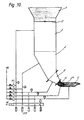
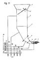
- the equipment in accordance with the invention is connected to the lower end of the storage silo 1 by means of a closing valve 2.
- the equipment comprises five packaging compartments 3 to 7 one after the other.
- the compartments constitute one unified space.
- Inside the impermeable exterior wall 8 of the equipment there is a porous metallic lining sheet 9, placed at a specified distance from the exterior wall.
- the equipment is constructed in such a way that the distance between the exterior wall and the porous sheet is maintained even if air is sucked off out of the space between the wall and the lining.
- the density of the porous sheet is in such a way optimized that the product to be packaged does not flow through the lining. Only the air or gas contained in the product passes through the sheet.
- the space between the exterior wall 8 and the lining material 9 is, at each packaging compartment, divided into separate compartments by means of air-tight partition walls.
- Each packaging compartment is connected with a pipe 10 to 14, which is connected both to a source of vacuum 15 and to a source of compressed air 16.
- the pipe system is provided with five pressure regulating valves 17, one at each branch next to the pressure source, and with a pressure regulating valve 18 at the branch next to the vacuum source.
- Each pipe 10 to 14 is provided , with a pressure gauge 19.
- the vacuum source is provided with five suction valves 20, connected to the branches related to each of the pipes 10 to 14.
- the lowermost packaging compartment 6 is connected by means of the closing valve 21 to the horizontal outlet pipe 7, from which the material to be packaged is removed at 22.
- the cross- section of the packaging compartments becomes smaller towards the outlet end of the equipment.
- each valve 17 is shown as fully black when it is open and with mere contours when it is closed.
- the suction valves 20 are shown as being either open or closed.
- Fig. 2 the closing valve of the upper chamber has just been opened and the packaging compartments have been filled with the material flowing down from the silo 1.
- the flowing down has been aided by vacuum guided into the packaging compartment 6, owing to which the material to be treated does not have to displace the quantity of air that would possibly be otherwise present in the packaging compartments.
- the condensing effect is intensified by allowing the vacuum to act upon all of the packaging compartments simultaneously, at the same time as the valves 2 and 21 are closed.
- the degree of condensing can be adjusted by varying the vacuum and the time used.
- the bottom valve 21 has been opened and the pressure to be directed at the packaging compartments, appropriately adjusted for each of the packaging compartments separately by means of the regulating valves, forces the condensed material to attempt to flow out through the bottom valve.
- the air guided into the packaging compartments under pressure passes through the porous lining material 9 and forms a layer that reduces the friction between the material to be treated and the porous face.
- Fig. 9 corresponds to that shown in Fig. 8.
- a deposit corresponding to the original uncondensed material starts being formed in the packaging compartment.
- Fig. 11 the top valve 2 is opened, whereby the material in the storage silo 1 starts flowing into the compartment 3. At the same time, the valve has been closed, and the vacuum is directed at the bottom-most packaging compartment 6, whereat the material aerated at the final stage of the emptying can be condensed again. If necessary, the compartment 7 is emptied by applying positive pressure to the compartment.
- the equipment may also be a so-called pressure transmitter, whereby the guiding of the condensed material into the transfer pipe can be controlled easily.
Landscapes
- Mechanical Engineering (AREA)
- Engineering & Computer Science (AREA)
- Filling Or Emptying Of Bunkers, Hoppers, And Tanks (AREA)
- Filtering Of Dispersed Particles In Gases (AREA)
- Cyclones (AREA)
- Crushing And Grinding (AREA)
- Disintegrating Or Milling (AREA)
- Vacuum Packaging (AREA)
- Basic Packing Technique (AREA)
- Nitrogen Condensed Heterocyclic Rings (AREA)
- Plural Heterocyclic Compounds (AREA)
- Air Transport Of Granular Materials (AREA)
- Coating Apparatus (AREA)
Priority Applications (1)
| Application Number | Priority Date | Filing Date | Title |
|---|---|---|---|
| AT84105067T ATE23973T1 (de) | 1983-05-11 | 1984-05-04 | Anordnung fuer die entfernung von luft aus koernigen stoffen. |
Applications Claiming Priority (2)
| Application Number | Priority Date | Filing Date | Title |
|---|---|---|---|
| FI831654A FI67064C (fi) | 1983-05-11 | 1983-05-11 | Anordning foer avlaegsning av luft ur pulverartade material |
| FI831654 | 1983-05-11 |
Publications (2)
| Publication Number | Publication Date |
|---|---|
| EP0125585A1 EP0125585A1 (en) | 1984-11-21 |
| EP0125585B1 true EP0125585B1 (en) | 1986-12-03 |
Family
ID=8517192
Family Applications (1)
| Application Number | Title | Priority Date | Filing Date |
|---|---|---|---|
| EP84105067A Expired EP0125585B1 (en) | 1983-05-11 | 1984-05-04 | Equipment for the removal of air out of pulverulent materials |
Country Status (9)
| Country | Link |
|---|---|
| US (1) | US4573504A (da) |
| EP (1) | EP0125585B1 (da) |
| JP (1) | JPS6118630A (da) |
| AT (1) | ATE23973T1 (da) |
| DE (1) | DE3461520D1 (da) |
| DK (1) | DK157073C (da) |
| FI (1) | FI67064C (da) |
| NO (1) | NO158371C (da) |
| SU (1) | SU1258322A3 (da) |
Cited By (1)
| Publication number | Priority date | Publication date | Assignee | Title |
|---|---|---|---|---|
| US5747105A (en) | 1996-04-30 | 1998-05-05 | Owens Corning Fiberglas Technology Inc. | Traversing nozzle for applying granules to an asphalt coated sheet |
Families Citing this family (24)
| Publication number | Priority date | Publication date | Assignee | Title |
|---|---|---|---|---|
| EP0224621A1 (en) * | 1985-11-19 | 1987-06-10 | Portals Engineering Limited | Powder flow control valve |
| GB2158813B (en) * | 1984-05-18 | 1988-01-20 | Loughborough Consult Ltd | Powder flow control valve |
| GB8727425D0 (en) * | 1987-11-23 | 1987-12-23 | Portals Eng Ltd | Powder flow control valves |
| GB8817708D0 (en) * | 1988-07-25 | 1988-09-01 | Portals Eng Ltd | Improvements in filling machines |
| GB2227482A (en) * | 1989-01-26 | 1990-08-01 | Exprocad Services Ltd | Fluidising bulk particulate material |
| US5244019A (en) * | 1989-09-15 | 1993-09-14 | Better Agricultural Goals Corp. | Vacuum fill system |
| US5509451A (en) * | 1989-09-15 | 1996-04-23 | B.A.G. Corporation | Vacuum fill system |
| US5538053A (en) * | 1989-09-15 | 1996-07-23 | Better Agricultural Goals Corporation | Vacuum densifier with auger |
| US5234037A (en) * | 1989-09-15 | 1993-08-10 | B.A.G. Corporation | Vacuum fill system |
| US5447183A (en) * | 1989-09-15 | 1995-09-05 | B.A.G. Corp. | Vacuum fill system |
| US5531252A (en) * | 1989-09-15 | 1996-07-02 | B.A.G. Corporation | Vacuum fill system |
| DE4103835A1 (de) * | 1991-02-08 | 1992-08-13 | Hassia Redatron Gmbh | Verfahren und vorrichtung zum haltbaren verpacken von lebensmitteln |
| JPH0798160B2 (ja) * | 1993-02-03 | 1995-10-25 | 忠 庄司 | コンクリート製電柱の粉砕処理装置 |
| US5599581A (en) * | 1993-11-02 | 1997-02-04 | Owens Corning Fiberglas Technology, Inc. | Method for pneumatically controlling discharge of particulate material |
| US5520889A (en) * | 1993-11-02 | 1996-05-28 | Owens-Corning Fiberglas Technology, Inc. | Method for controlling the discharge of granules from a nozzle onto a coated sheet |
| WO1995012457A1 (en) * | 1993-11-02 | 1995-05-11 | Owens Corning | Pneumatic granule blender for asphalt shingles |
| US5405647A (en) * | 1993-11-02 | 1995-04-11 | Owens-Corning Fiberglass Technology Inc. | Method for applying granules to a moving coated asphalt sheet to form areas having sharp leading and trailing edges |
| US5624522A (en) * | 1995-06-07 | 1997-04-29 | Owens-Corning Fiberglas Technology Inc. | Method for applying granules to strip asphaltic roofing material to form variegated shingles |
| RU2123461C1 (ru) * | 1997-10-03 | 1998-12-20 | Юрий Всеволодович Копылов | Устройство для наполнения клапанных мешков сыпучим материалом |
| ATE252022T1 (de) * | 1999-08-23 | 2003-11-15 | Ciba Sc Holding Ag | Verfahren und vorrichtung zum verdichten von pulverförmigem material |
| US20050269369A1 (en) * | 2004-06-02 | 2005-12-08 | Pfeiffer John W | Rotary feeder valve for pneumatic conveying system |
| US10228077B2 (en) | 2017-03-15 | 2019-03-12 | The Young Industries, Inc. | Fluidizing butterfly valve, and system |
| US12589408B2 (en) | 2020-11-06 | 2026-03-31 | System Ceramics S.P.A. | Dispensing device for decorating ceramic tiles with granular or powdered materials |
| US20240367827A1 (en) * | 2021-05-10 | 2024-11-07 | Concetti S.P.A. | Method and equipment for filling bags with a deaerated amount of product, with additional deaerator or compaction |
Family Cites Families (3)
| Publication number | Priority date | Publication date | Assignee | Title |
|---|---|---|---|---|
| CH533537A (de) * | 1970-12-21 | 1973-02-15 | Gericke & Co | Vorrichtung zum Abfüllen eines Behältnisses mit verdichtetem, pulvrigem Gut |
| US3716082A (en) * | 1971-01-22 | 1973-02-13 | Douglas & Lomason Co | Pressure type bag filling machine |
| US3799622A (en) * | 1971-12-28 | 1974-03-26 | Universal Dynamics Corp | Multi-station loader for particulate material |
-
1983
- 1983-05-11 FI FI831654A patent/FI67064C/fi not_active IP Right Cessation
-
1984
- 1984-05-04 DE DE8484105067T patent/DE3461520D1/de not_active Expired
- 1984-05-04 EP EP84105067A patent/EP0125585B1/en not_active Expired
- 1984-05-04 AT AT84105067T patent/ATE23973T1/de not_active IP Right Cessation
- 1984-05-08 NO NO841842A patent/NO158371C/no unknown
- 1984-05-08 DK DK226884A patent/DK157073C/da not_active IP Right Cessation
- 1984-05-09 JP JP59091163A patent/JPS6118630A/ja active Pending
- 1984-05-10 SU SU3739758A patent/SU1258322A3/ru active
- 1984-05-11 US US06/609,130 patent/US4573504A/en not_active Expired - Fee Related
Cited By (1)
| Publication number | Priority date | Publication date | Assignee | Title |
|---|---|---|---|---|
| US5747105A (en) | 1996-04-30 | 1998-05-05 | Owens Corning Fiberglas Technology Inc. | Traversing nozzle for applying granules to an asphalt coated sheet |
Also Published As
| Publication number | Publication date |
|---|---|
| DK157073C (da) | 1990-04-16 |
| NO158371C (no) | 1988-08-31 |
| JPS6118630A (ja) | 1986-01-27 |
| FI831654A0 (fi) | 1983-05-11 |
| SU1258322A3 (ru) | 1986-09-15 |
| FI67064B (fi) | 1984-09-28 |
| DK157073B (da) | 1989-11-06 |
| EP0125585A1 (en) | 1984-11-21 |
| DE3461520D1 (en) | 1987-01-15 |
| FI67064C (fi) | 1985-01-10 |
| DK226884A (da) | 1984-11-12 |
| DK226884D0 (da) | 1984-05-08 |
| ATE23973T1 (de) | 1986-12-15 |
| NO158371B (no) | 1988-05-24 |
| NO841842L (no) | 1984-11-12 |
| US4573504A (en) | 1986-03-04 |
Similar Documents
| Publication | Publication Date | Title |
|---|---|---|
| US4573504A (en) | Equipment for the removal of air out of pulverulent materials | |
| US2815621A (en) | Method and apparatus for filling open mouth receptacles | |
| US3260285A (en) | Apparatus and method for filling containers for pulverulent material | |
| US5244019A (en) | Vacuum fill system | |
| US6089283A (en) | Method of filling containers | |
| EP0417675B1 (en) | Vacuum fill system | |
| US4264243A (en) | Constant vacuum barge unloading system | |
| US5234037A (en) | Vacuum fill system | |
| US5518048A (en) | Full sack compressor | |
| US4747732A (en) | Closed apparatus with potential fluidization for horizontally conveying powder material in a dense bed | |
| US2954203A (en) | Filling machine | |
| US3840155A (en) | Nuclear fuel handling powder container | |
| US3045717A (en) | Method and apparatus for preparing measured charges of material and dispensing them ito cavities | |
| EP0686588A2 (en) | Material handling apparatus | |
| US3315824A (en) | Method and apparatus for continuous gravity feed of fluent materials | |
| US6668522B2 (en) | Method for compacting bags | |
| US2927658A (en) | Reducing powder bulk | |
| AU2003207411A1 (en) | Method for compacting bags | |
| GB1265801A (da) | ||
| EP0443349A1 (en) | Powder dispensing apparatus | |
| US3039827A (en) | Rock duster | |
| US3832974A (en) | Fluidized bed coating apparatus | |
| GB943810A (en) | Apparatus for filling powdered or granular material into containers | |
| WO2003000553A1 (en) | Densifying bag filling machine | |
| US4753565A (en) | Method of and apparatus for discharging solids from a pressurized container |
Legal Events
| Date | Code | Title | Description |
|---|---|---|---|
| PUAI | Public reference made under article 153(3) epc to a published international application that has entered the european phase |
Free format text: ORIGINAL CODE: 0009012 |
|
| AK | Designated contracting states |
Designated state(s): AT BE CH DE FR GB IT LI NL SE |
|
| 17P | Request for examination filed |
Effective date: 19850308 |
|
| ITF | It: translation for a ep patent filed | ||
| GRAA | (expected) grant |
Free format text: ORIGINAL CODE: 0009210 |
|
| AK | Designated contracting states |
Kind code of ref document: B1 Designated state(s): AT BE CH DE FR GB IT LI NL SE |
|
| REF | Corresponds to: |
Ref document number: 23973 Country of ref document: AT Date of ref document: 19861215 Kind code of ref document: T |
|
| BECA | Be: change of holder's address |
Free format text: 861203 *HACKMAN-MKT OYPL 31, SF-48101 KOTKA 10 |
|
| BECH | Be: change of holder |
Free format text: 861203 *HACKMAN-MKT OY |
|
| REF | Corresponds to: |
Ref document number: 3461520 Country of ref document: DE Date of ref document: 19870115 |
|
| ET | Fr: translation filed | ||
| PLBE | No opposition filed within time limit |
Free format text: ORIGINAL CODE: 0009261 |
|
| STAA | Information on the status of an ep patent application or granted ep patent |
Free format text: STATUS: NO OPPOSITION FILED WITHIN TIME LIMIT |
|
| 26N | No opposition filed | ||
| REG | Reference to a national code |
Ref country code: GB Ref legal event code: 732 |
|
| REG | Reference to a national code |
Ref country code: FR Ref legal event code: TP |
|
| NLS | Nl: assignments of ep-patents |
Owner name: HACKMAN-MKT OY TE KOTKA, FINLAND. |
|
| PGFP | Annual fee paid to national office [announced via postgrant information from national office to epo] |
Ref country code: SE Payment date: 19920413 Year of fee payment: 9 |
|
| PGFP | Annual fee paid to national office [announced via postgrant information from national office to epo] |
Ref country code: FR Payment date: 19920430 Year of fee payment: 9 Ref country code: CH Payment date: 19920430 Year of fee payment: 9 |
|
| PGFP | Annual fee paid to national office [announced via postgrant information from national office to epo] |
Ref country code: GB Payment date: 19920508 Year of fee payment: 9 |
|
| PGFP | Annual fee paid to national office [announced via postgrant information from national office to epo] |
Ref country code: BE Payment date: 19920514 Year of fee payment: 9 |
|
| PGFP | Annual fee paid to national office [announced via postgrant information from national office to epo] |
Ref country code: AT Payment date: 19920525 Year of fee payment: 9 |
|
| ITTA | It: last paid annual fee | ||
| PGFP | Annual fee paid to national office [announced via postgrant information from national office to epo] |
Ref country code: NL Payment date: 19920531 Year of fee payment: 9 |
|
| PGFP | Annual fee paid to national office [announced via postgrant information from national office to epo] |
Ref country code: DE Payment date: 19920731 Year of fee payment: 9 |
|
| PG25 | Lapsed in a contracting state [announced via postgrant information from national office to epo] |
Ref country code: GB Effective date: 19930504 Ref country code: AT Effective date: 19930504 |
|
| PG25 | Lapsed in a contracting state [announced via postgrant information from national office to epo] |
Ref country code: SE Effective date: 19930505 |
|
| PG25 | Lapsed in a contracting state [announced via postgrant information from national office to epo] |
Ref country code: LI Effective date: 19930531 Ref country code: CH Effective date: 19930531 Ref country code: BE Effective date: 19930531 |
|
| BERE | Be: lapsed |
Owner name: HACKMAN-MKT OY Effective date: 19930531 |
|
| PG25 | Lapsed in a contracting state [announced via postgrant information from national office to epo] |
Ref country code: NL Effective date: 19931201 |
|
| GBPC | Gb: european patent ceased through non-payment of renewal fee |
Effective date: 19930504 |
|
| NLV4 | Nl: lapsed or anulled due to non-payment of the annual fee | ||
| PG25 | Lapsed in a contracting state [announced via postgrant information from national office to epo] |
Ref country code: FR Effective date: 19940131 |
|
| REG | Reference to a national code |
Ref country code: CH Ref legal event code: PL |
|
| PG25 | Lapsed in a contracting state [announced via postgrant information from national office to epo] |
Ref country code: DE Effective date: 19940201 |
|
| REG | Reference to a national code |
Ref country code: FR Ref legal event code: ST |
|
| EUG | Se: european patent has lapsed |
Ref document number: 84105067.7 Effective date: 19931210 |